manuals.online logo
Brands
  1. Home
  2. •
  3. Brands
  4. •
  5. Monacor
  6. •
  7. Controllers
  8. •
  9. Monacor CU-3MINI User manual

Monacor CU-3MINI User manual

ELECTRONICS FOR SPECIALISTS ELECTRONICS FOR SPECIALISTS ELECTRONICS FOR SPECIALISTS ELECTRONICS FOR SPECIALISTS ELECTRONICS FOR SPECIALISTS ELECTRONICS
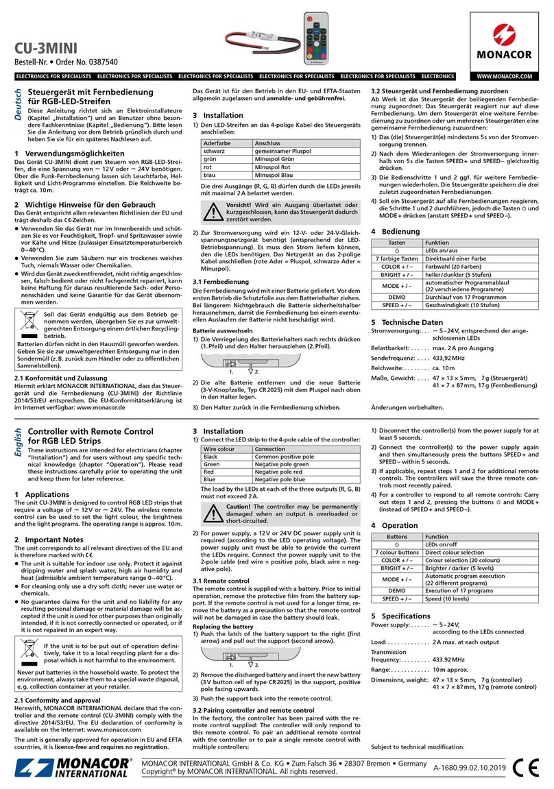
CU-3MINI
Bestell-Nr. • Order no. 38.7540
MONACOR INTERNATIONAL GmbH & Co. KG • Zum Falsch 36 • 28307 Bremen • Germany
Copyright©by MONACOR INTERNATIONAL. All rights reserved. A-1680.99.01.08.2015
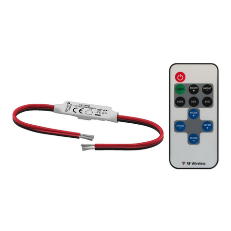
Controller with Remote Control
for RGB LED Strips
These instructions are intended for electricians (chapter
“Installation”) and for users without any specific tech-
nical knowledge (chapter “Operation”). Please read
these instructions carefully prior to operating the unit
and keep them for later reference.
1 Applications
The unit CU-3MINI is designed to control RGB LED strips that
require a voltage of 12V⎓or 24V⎓. The wireless remote con-
trol can be used to set the light colour, the brightness and the
light programs. The operating range is approx. 10m.
2 Important Notes
The unit corresponds to all relevant directives of the EU and
is therefore marked with .
• The unit is suitable for indoor use only. Protect it against
dripping water and splash water, high air humidity and
heat (admissible ambient temperature range 0–40°C).
• For cleaning only use a dry soft cloth; never use water or
chemicals.
• No guarantee claims for the unit and no liability for any
resulting personal damage or material damage will be ac-
cepted if the unit is used for other purposes than originally
intended, if it is not correctly connected or operated, or if
it is not repaired in an expert way.
If the unit is to be put out of operation defini-
tively, take it to a local recycling plant for a dis-
posal which is not harmful to the environment.
Never put batteries in the household waste. To protect the
environment, always take them to a special waste disposal,
e.g. collection container at your retailer.
2.1 Conformity and approval
Herewith, MONACOR INTERNATIONAL declare that the
controller and the remote control (CU-3MINI) comply with
the directive 2014/53/EU. The EU declaration of conformity
is available on request from MONACOR INTERNATIONAL.
The unit is generally approved for operation in EU and EFTA
countries, it is licence-free and requires no registration.
3 Installation
1) Connect the LED strip to the 4-pole cable of the controller:
Wire colour Connection
Black Common positive pole
Green Negative pole green
Red Negative pole red
Blue Negative pole blue
The load by the LEDs at each of the three outputs (R, G, B)
must not exceed 2A.
Caution! The controller may be permanently
damaged when an output is overloaded or
short-circuited.
2) For power supply, a 12V or 24VDC power supply unit is
required (according to the LED operating voltage). The
power supply unit must be able to provide the current
the LEDs require. Connect the power supply unit to the
2-pole cable (red wire = positive pole, black wire = neg-
ative pole).
3.1 Remote control
The remote control is supplied with a battery. Prior to initial
operation, remove the protective film from the battery sup-
port. If the remote control is not used for a longer time, re-
move the battery as a precaution so that the remote control
will not be damaged in case the battery should leak.
Replacing the battery
1) Push the latch of the battery support to the right (first
arrow) and pull out the support (second arrow).
1. 2.
2) Remove the discharged battery and insert the new battery
(3V button cell of type CR2025) in the support, positive
pole facing upwards.
3) Push the support back into the remote control.
3.2 Pairing controller and remote control
In the factory, the controller has been paired with the re-
mote control supplied: The controller will only respond to
this remote control. To pair an additional remote control
with the controller or to pair a single remote control with
multiple controllers:
1) Disconnect the controller(s) from the power supply for at
least 5 seconds.
2) Connect the controller(s) to the power supply again
and then simultaneously press the buttons SPEED+ and
SPEED– within 5 seconds.
3) If applicable, repeat steps 1 and 2 for additional remote
controls. The controllers will save the three remote con-
trols most recently paired.
4) For a controller to respond to all remote controls: Carry
out steps 1 and 2, pressing the buttons and MODE+
(instead of SPEED+ and SPEED–).
4 Operation
Buttons Function
LEDs on/off
7 colour buttons Direct colour selection
COLOR + / – Colour selection (20 colours)
BRIGHT + / – Brighter / darker (5 levels)
MODE + / – Automatic program execution
(22 different programs)
DEMO Execution of 17 programs
SPEED + / – Speed (10 levels)
5 Specifications
Power supply: . . . . . . 5 – 24 V⎓,
according to the LEDs connected
Load: . . . . . . . . . . . . . 2 A max. at each output
Transmission
frequency:. . . . . . . . . 433.92 MHz
Range:. . . . . . . . . . . . 10m approx.
Dimensions, weight:. 47 × 13 × 5mm, 7g (controller)
41 × 7 × 87mm, 17g (remote control)
Subject to technical modification.
Steuergerät mit Fernbedienung
für RGB-LED-Streifen
Diese Anleitung richtet sich an Elektroinstallateure
(Kapitel „Installation“) und an Benutzer ohne beson-
dere Fachkenntnisse (Kapitel „Bedienung“). Bitte lesen
Sie die Anleitung vor dem Betrieb gründlich durch und
heben Sie sie für ein späteres Nachlesen auf.
1 Verwendungsmöglichkeiten
Das Gerät CU-3MINI dient zum Steuern von RGB-LED-Strei-
fen, die eine Spannung von 12V⎓oder 24V⎓benötigen.
Über die Funk-Fernbedienung lassen sich Leuchtfarbe, Hel-
ligkeit und Licht-Programme einstellen. Die Reichweite be-
trägt ca. 10m.
2 Wichtige Hinweise für den Gebrauch
Das Gerät entspricht allen relevanten Richtlinien der EU und
ist deshalb mit gekennzeichnet.
• Verwenden Sie das Gerät nur im Innenbereich und schüt-
zen Sie es vor Feuchtigkeit, Tropf- und Spritzwasser sowie
vor Kälte und Hitze (zulässiger Einsatztemperaturbereich
0–40°C).
• Verwenden Sie zum Säubern nur ein trockenes weiches
Tuch, niemals Wasser oder Chemikalien.
• Wird das Gerät zweckentfremdet, nicht richtig angeschlos-
sen, falsch bedient oder nicht fachgerecht repariert, kann
keine Haftung für daraus resultierende Sach- oder Perso-
nenschäden und keine Garantie für das Gerät übernom-
men werden.
Soll das Gerät endgültig aus dem Betrieb genom-
men werden, übergeben Sie es zur umweltgerech-
ten Entsorgung einem örtlichen Recyclingbetrieb.
Batterien dürfen nicht in den Hausmüll geworfen werden.
Geben Sie sie zur umweltgerechten Entsorgung nur in den
Sondermüll (z.B. zurück zum Händler oder zu öffentlichen
Sammelstellen).
2.1 Konformität und Zulassung
Hiermit erklärt MONACOR INTERNATIONAL, dass das Steuer-
gerät und die Fernbedienung (CU-3MINI) der Richtlinie
2014/53/EU entsprechen. Die EU-Konformitätserklärung
kann bei MONACOR INTERNATIONAL angefordert werden.
Das Gerät ist für den Betrieb in den EU- und EFTA-Staaten
allgemein zugelassen und anmelde- und gebührenfrei.
3 Installation
1) Den LED-Streifen an das 4-polige Kabel des Steuergeräts
anschließen:
Aderfarbe Anschluss
schwarz gemeinsamer Pluspol
grün Minuspol Grün
rot Minuspol Rot
blau Minuspol Blau
Die drei Ausgänge (R, G, B) dürfen durch die LEDs jeweils
mit maximal 2A belastet werden.
Vorsicht! Wird ein Ausgang überlastet oder
kurzgeschlossen, kann das Steuergerät dadurch
zerstört werden.
2) Zur Stromversorgung wird ein 12-V- oder 24-V-Gleich-
spannungsnetzgerät benötigt (entsprechend der LED-
Betriebsspannung). Es muss den Strom liefern können,
den die LEDs benötigen. Das Netzgerät an das 2-polige
Kabel anschließen (rote Ader = Pluspol, schwarze Ader =
Minuspol).
3.1 Fernbedienung
Die Fernbedienung wird mit einer Batterie geliefert. Vor dem
ersten Betrieb die Schutzfolie aus dem Batteriehalter ziehen.
Bei längerem Nichtgebrauch die Batterie sicherheitshalber
herausnehmen, damit die Fernbedienung bei einem eventu-
ellen Auslaufen der Batterie nicht beschädigt wird.
Batterie auswechseln
1) Die Verriegelung des Batteriehalters nach rechts drücken
(1.Pfeil) und den Halter herausziehen (2.Pfeil).
1. 2.
2) Die alte Batterie entfernen und die neue Batterie
(3-V-Knopfzelle, Typ CR 2025) mit dem Pluspol nach oben
in den Halter legen.
3) Den Halter zurück in die Fernbedienung schieben.
3.2 Steuergerät und Fernbedienung zuordnen
Ab Werk ist das Steuergerät der beiliegenden Fernbedie-
nung zugeordnet: Das Steuergerät reagiert nur auf diese
Fernbedienung. Um dem Steuergerät eine weitere Fernbe-
dienung zu zuordnen oder um mehreren Steuergeräten eine
gemeinsame Fernbedienung zuzuordnen:
1) Das (die) Steuergerät(e) mindestens 5s von der Stromver-
sorgung trennen.
2) Nach dem Wiederanlegen der Stromversorgung inner-
halb von 5s die Tasten SPEED+ und SPEED– gleichzeitig
drücken.
3) Die Bedienschritte 1 und 2 ggf. für weitere Fernbedie-
nungen wiederholen. Die Steuergeräte speichern die drei
zuletzt zugeordneten Fernbedienungen.
4) Soll ein Steuergerät auf alle Fernbedienungen reagieren,
die Schritte 1 und 2 durchführen, jedoch die Tasten und
MODE+ drücken (anstatt SPEED+ und SPEED–).
4 Bedienung
Tasten Funktion
LEDs an/aus
7 farbige Tasten Direktwahl einer Farbe
COLOR + / – Farbwahl (20 Farben)
BRIGHT + / – heller/dunkler (5 Stufen)
MODE + / – automatischer Programmablauf
(22 verschiedene Programme)
DEMO Durchlauf von 17 Programmen
SPEED + / – Geschwindigkeit (10 Stufen)
5 Technische Daten
Stromversorgung:. . . 5 – 24 V⎓, entsprechend der ange-
schlossenen LEDs
Belastbarkeit: . . . . . . max. 2 A pro Ausgang
Sendefrequenz: . . . . 433,92 MHz
Reichweite: . . . . . . . . ca. 10 m
Maße, Gewicht: . . . . 47 × 13 × 5 mm, 7g (Steuergerät)
41 × 7 × 87mm, 17g (Fernbedienung)
Änderungen vorbehalten.
DeutschEnglish
ELECTRONICS FOR SPECIALISTS ELECTRONICS FOR SPECIALISTS ELECTRONICS FOR SPECIALISTS ELECTRONICS FOR SPECIALISTS ELECTRONICS FOR SPECIALISTS ELECTRONICS
MONACOR INTERNATIONAL GmbH & Co. KG • Zum Falsch 36 • 28307 Bremen • Germany
Copyright©by MONACOR INTERNATIONAL. All rights reserved. A-1680.99.01.08.2015
Unità di controllo con telecomando
per strisce con LED RGB
Queste istruzioni sono rivolte ad installatori elettrici (ca-
pitolo “Installazione”) e agli utenti senza conoscenze
tecniche specifiche (capitolo “Funzionamento”). Vi pre-
ghiamo di leggerle attentamente prima della messa in
funzione e di conservarle per un uso futuro.
1 Possibilità d‘impiego
L’apparecchio CU-3MINI serve per comandare delle strisce
con LED RGB che richiedono una tensione di 12V⎓o 24V⎓.
Tramite il telecomando wireless si possono impostare il co-
lore delle luci, la luminosità e i programmi di luci. La portata
è di 10m ca.
2 Avvertenze importanti per l‘uso
L’apparecchio è conforme a tutte le direttive rilevanti dell’UE
e pertanto porta la sigla .
• Usare l’apparecchio solo all’interno di locali e proteggerlo
dall’umidità, dall’acqua gocciolante e dagli spruzzi d’ac-
qua, nonché dal freddo e dal calore (temperatura d’im-
piego ammessa fra 0 e 40°C).
• Per la pulizia usare solo un panno morbido, asciutto; non
impiegare mai acqua o prodotti chimici.
• Nel caso d’uso improprio, di collegamenti sbagliati,
d’impiego scorretto o di riparazione non a regola d’arte
dell’apparecchio, non si assume nessuna responsabilità per
eventuali danni consequenziali a persone o a cose e non si
assume nessuna garanzia per l’apparecchio.
Se si desidera eliminare l’apparecchio definitiva-
mente, consegnarlo per lo smaltimento ad un’isti-
tuzione locale per il riciclaggio.
Non gettare le batterie scariche o difettose nelle immon-
dizie di casa bensì negli appositi contenitori (p.es. presso
il vostro rivenditore)
2.1 Conformità e omologazione
La MONACOR INTERNATIONAL dichiara che l’unità di con-
trollo e il telecomando (CU-3MINI) sono conformi alla diret-
tiva 2014/53/UE. La dichiarazione di conformità UE può essere
richiesta presso MONACOR INTERNATIONAL. L’apparecchio è
omologato per l’impiego negli stati dell’UE e dell’EFTA e non
richiede né registrazione né pagamento di tasse.
3 Installazione
1) Collegare la striscia con LED con il cavo a 4 poli dell’unità
di controllo:
Colore del
conduttore Contatto
Nero Polo positivo comune
Verde Polo negativo verde
Rosso Polo negativo rosso
Blu Polo negativo blu
Le tre uscite (R, G, B) possono essere caricate dai LED
ognuno con non più di 2A.
Attenzione! Se un’uscita è sovraccaricata o
messa in corto, ciò può provocare la distruzione
dell’unità di controllo.
2) Per l’alimentazione è richiesto un alimentatore per ten-
sione continua di 12V o di 24V (secondo la tensione
d’esercizio dei LED). Deve essere in grado di fornire la
corrente richiesta dai LED. Collegare l’alimentatore con il
cavo a 2poli (conduttore rosso = polo positivo, conduttore
nero = polo negativo).
3.1 Telecomando
Il telecomando viene fornito con una batteria. Prima dell’uso
occorre sfilare la pellicola protettiva dal portabatteria. In caso
di mancato uso prolungato conviene togliere la batteria per
non danneggiare il telecomando se la batteria dovesse perdere.
Sostituire la batteria
1) Spingere a destra il blocco del portabatteria (1. freccia) e
togliere il portabatteria
(2.freccia).
2) Togliere la vecchia bat-
teria e inserire una nuova batteria (3V a bottone, tipo
CR2025) con il polo positivo rivolto verso l‘alto.
3) Rimettere il portabatteria nel telecomando.
1. 2.
3.2 Coordinare unità di controllo e telecomando
Dalla fabbrica, l’unità di controllo è coordinata al teleco-
mando in dotazione: l’unità di controllo reagisce solo a
quel telecomando. Per coordinare all’unità di controllo un
ulteriore telecomando oppure per coordinare a più unità di
controllo un telecomando comune:
1) Staccare la/le unità di controllo per un minimo di 5s
dall‘alimentazione.
2) Dopo aver rimesso l’alimentazione, premere entro 5s con-
temporaneamente i tasti SPEED+ e SPEED–.
3) Eventualmente ripetere i punti 1 e 2 per ulteriori tele-
comandi. Le unità di comando memorizzano i tre tele-
comandi coordinati per ultimi.
4) Se un’unità di comando deve reagire a tutti i telecomandi,
eseguire i punti 1 e 2, premendo comunque i tasti e
MODE+ (invece di SPEED+ e SPEED–).
4 Funzionamento
Tasti Funzione
LED on/off
7 tasti colorati Scelta diretta di un colore
COLOR + / – Scelta dei colori (20 colori)
BRIGHT + / – Più chiaro/più scuro (5 livelli)
MODE + / – Svolgimento automatico del programma
(22 programmi differenti)
DEMO Svolgimento di 17 programmi
SPEED + / – Velocità (10 livelli)
5 Dati tecnici
Alimentazione:. . . . . 5–24V⎓, secondo i LED collegati
Potenza :. . . . . . . . . . max. 2A per uscita
Frequenza
di trasmissione:. . . . . 433,92 MHz
Portata: . . . . . . . . . . . ca. 10m
Dimensioni, peso
Unità di comando: 47 × 13 × 5mm, 7 g
Telecomando: . . . 41 × 7 × 87mm, 17g
Con riserva di modifiche tecniche.
CU-3MINI
Réf. num. • Codice 38.7540
Contrôleur avec télécommande
pour flexleds RGB
Cette notice s’adresse aux électriciens (chapitre «Installa-
tion») et aux utilisateurs sans connaissances techniques
particulières (chapitre «Utilisation»). Veuillez lire la pré-
sente notice avec attention avant l’installation et conser-
vez-la pour pouvoir vous y reporter ultérieurement.
1 Possibilités d’utilisation
Le CU-3MINI permet de gérer des flexleds RGB nécessitant
une tension de 12V⎓ou 24V⎓. Via la télécommande sans
fil, vous pouvez régler la couleur, la luminosité et les pro-
grammes de lumière. La portée est de 10m environ.
2 Conseils importants d’utilisation
L’appareil répond à toutes les directives nécessaires de
l’Union européenne et porte donc le symbole .
• L’appareil n’est conçu que pour une utilisation en inté-
rieur. Protégez-le de tout type de projections d’eau, des
éclaboussures, d’une humidité élevée de l’air et de la cha-
leur (plage de température de fonctionnement autorisée:
0–40°C).
• Pour le nettoyage, utilisez un chiffon doux et sec, en aucun
cas d’eau ou de produits chimiques.
• Nous déclinons toute responsabilité en cas de dommages
matériels ou corporels résultants si l’appareil est utilisé
dans un but autre que celui pour lequel il a été conçu, s’il
n’est pas correctement branché ou utilisé, ou s’il n’est pas
réparé par une personne habilitée, en outre, la garantie
deviendrait caduque.
Lorsque l’appareil est définitivement retiré du ser-
vice, vous devez le déposer dans une usine de re-
cyclage adaptée pour contribuer à son élimination
non polluante.
Ne jetez pas les batteries usagées dans la poubelle domes-
tique ; déposez-les dans un container spécifique ou chez
votre détaillant.
2.1 Conformité et déclaration
Par la présente, MONACOR INTERNATIONAL déclare que le
contrôleur et la télécommande (CU-3MINI) sont en confor-
mité avec la directive 2014/53/UE. La déclaration UE de
conformité peut être demandée auprès de MONACOR INTER-
NATIONAL. L’appareil est autorisé sans déclaration ni taxe
dans les pays de l’Union européenne et de l’A.E.L.E.
3 Installation
1) Reliez le flexled au cordon 4 pôles du contrôleur :
Couleur
conducteur Branchement
noir pôle plus commun
vert pôle moins vert
rouge pôle moins rouge
bleu pôle moins bleu
Les trois sorties (R, G, B) ne doivent pas avoir une charge
par les LEDs de plus de 2A.
Attention ! Si une sortie est en surcharge ou en
court-circuit, le contrôleur peut être détruit.
2) Pour l’alimentation, un bloc secteur 12V⎓ou 24V⎓est
nécessaire (selon la tension d’alimentation des LEDs). Il
doit pouvoir délivrer le courant dont les LEDs ont besoin.
Reliez le bloc secteur au cordon 2 pôles (conducteur rouge
= pôle plus, conducteur noir = pôle moins).
3.1 Télécommande
La télécommande est livrée avec une batterie. Avant la pre-
mière utilisation, retirez la feuille de protection du compar-
timent batterie. En cas de non utilisation prolongée, retirez
la batterie, elle pourrait couler et endommager la télécom-
mande.
Remplacement de la batterie
1) Poussez vers la droite le verrouillage du support de batte-
rie (flèche 1) et retirez le
support (flèche 2).
2) Retirez la batterie dé-
chargée, insérez la batterie neuve (pile bouton 3V, type
CR2025), pôle plus vers le haut.
3) Remettez le support en place dans la télécommande.
3.2 Attribution du contrôleur et de la télécommande
Au départ usine, le contrôleur est attribué à la télécommande
livrée : le contrôleur ne réagit qu’à cette télécommande.
Pour attribuer le contrôleur à une autre télécommande ou
1. 2.
pour attribuer plusieurs contrôleurs à une télécommande
commune :
1) Débranchez le (les) contrôleur(s) pendant 5sec. au moins.
2) Une fois l’alimentation à nouveau branchée, appuyez si-
multanément sur les touches SPEED+ et SPEED– dans un
délai de 5sec.
3) Répétez les points 1 et 2 si besoin pour d’autres télécom-
mandes. Les contrôleurs mémorisent les trois dernières
télécommandes attribuées.
4) Si un contrôleur doit réagirà toutes les télécommandes,
effectuez les points 1 et 2 mais en appuyant sur les touches
et MODE+ (à la place des touches SPEED+ et SPEED–).
4 Utilisation
Touches Fonction
I /LEDs on/off
7 touches en
couleur sélection directe d’une couleur
COLOR + / – sélection de couleurs (20 couleurs)
BRIGHT + / – plus clair/plus foncé (5 niveaux)
MODE + / – défilement automatique de programme
(22 programmes différents)
DEMO défilement de 17 programmes
SPEED + / – vitesse (10 niveaux)
5 Caractéristiques techniques
Alimentation: . . . . . 5–24V⎓, selon les LEDs branchées
Charge:. . . . . . . . . . . 2 A max. par sortie
Fréquence émission: 433,92MHz
Portée: . . . . . . . . . . . 10 m env.
Dimensions, poids: . 47 × 13 × 5mm, 7 g (contrôleur)
41 × 7 × 87mm, 17g (télécommande)
Tout droit de modification réservé.
FrançaisItaliano
CARTONS ET EMBALLAGE
PAPIER À TRIER
This manual suits for next models

1

Other Monacor Controllers manuals

Monacor PA VCA-202RN User manual

Monacor

Monacor PA VCA-202RN User manual

Monacor KB-100 User manual

Monacor

Monacor KB-100 User manual

Monacor DSM-26LAN Installation manual

Monacor

Monacor DSM-26LAN Installation manual

Monacor CU-3MINI User manual

Monacor

Monacor CU-3MINI User manual

Monacor CU-1MINI User manual

Monacor

Monacor CU-1MINI User manual

Monacor img Stage Line FSC-3 User manual

Monacor

Monacor img Stage Line FSC-3 User manual

Monacor PA-100ANC User manual

Monacor

Monacor PA-100ANC User manual

Monacor img Stage Line LC-6DMX User manual

Monacor

Monacor img Stage Line LC-6DMX User manual

Monacor CU-20R User manual

Monacor

Monacor CU-20R User manual

Monacor img Stage Line STROBE-1C User manual

Monacor

Monacor img Stage Line STROBE-1C User manual

Monacor VCA-202RN User manual

Monacor

Monacor VCA-202RN User manual

Monacor IMG Stageline FS-1440 User manual

Monacor

Monacor IMG Stageline FS-1440 User manual

Monacor IMG STAGELINE CU-3IR User manual

Monacor

Monacor IMG STAGELINE CU-3IR User manual

Monacor CU-10R User manual

Monacor

Monacor CU-10R User manual

Monacor img Stage Line CU-3LED User manual

Monacor

Monacor img Stage Line CU-3LED User manual

Monacor img Stage Line CU-1RC User manual

Monacor

Monacor img Stage Line CU-1RC User manual

Monacor KU-516 User manual

Monacor

Monacor KU-516 User manual

Popular Controllers manuals by other brands

Elan SpeakerCraft MRA664 Integration note

Elan

Elan SpeakerCraft MRA664 Integration note

ITT Advantage Actuator 2.0 Maintenance manual

ITT

ITT Advantage Actuator 2.0 Maintenance manual

Spectral Products AB300 Series user manual

Spectral Products

Spectral Products AB300 Series user manual

Rockwell Automation Allen-Bradley 150-E manual

Rockwell Automation

Rockwell Automation Allen-Bradley 150-E manual

Fisher MR108 Series instruction manual

Fisher

Fisher MR108 Series instruction manual

BleBox shutterBox 2.0 user manual

BleBox

BleBox shutterBox 2.0 user manual

Niles Auriel MRC-6430 System design guide

Niles

Niles Auriel MRC-6430 System design guide

ABB AC500 Series Application Example

ABB

ABB AC500 Series Application Example

Lenze 482 operating instructions

Lenze

Lenze 482 operating instructions

meitav-tec PYROBOX3/19 Installation and operating manual

meitav-tec

meitav-tec PYROBOX3/19 Installation and operating manual

Altronix StrikeIt1 installation guide

Altronix

Altronix StrikeIt1 installation guide

Berker 8526 51 00 Operation instructions

Berker

Berker 8526 51 00 Operation instructions

PureTools PT-C-HDCEC user manual

PureTools

PureTools PT-C-HDCEC user manual

Pololu Corporation Micro Maestro 6 user guide

Pololu Corporation

Pololu Corporation Micro Maestro 6 user guide

Johnson Controls FX-PCV1930 installation guide

Johnson Controls

Johnson Controls FX-PCV1930 installation guide

Samson 3725 series Mounting and operating instructions

Samson

Samson 3725 series Mounting and operating instructions

Ruijie Networks RG-WS6008 Series Hardware  installation and reference guide

Ruijie Networks

Ruijie Networks RG-WS6008 Series Hardware installation and reference guide

Burkert 6606 operating instructions

Burkert

Burkert 6606 operating instructions

manuals.online logo
manuals.online logoBrands
  • About & Mission
  • Contact us
  • Privacy Policy
  • Terms and Conditions

Copyright 2025 Manuals.Online. All Rights Reserved.