manuals.online logo
Brands
  1. Home
  2. •
  3. Brands
  4. •
  5. Monacor
  6. •
  7. Speakers
  8. •
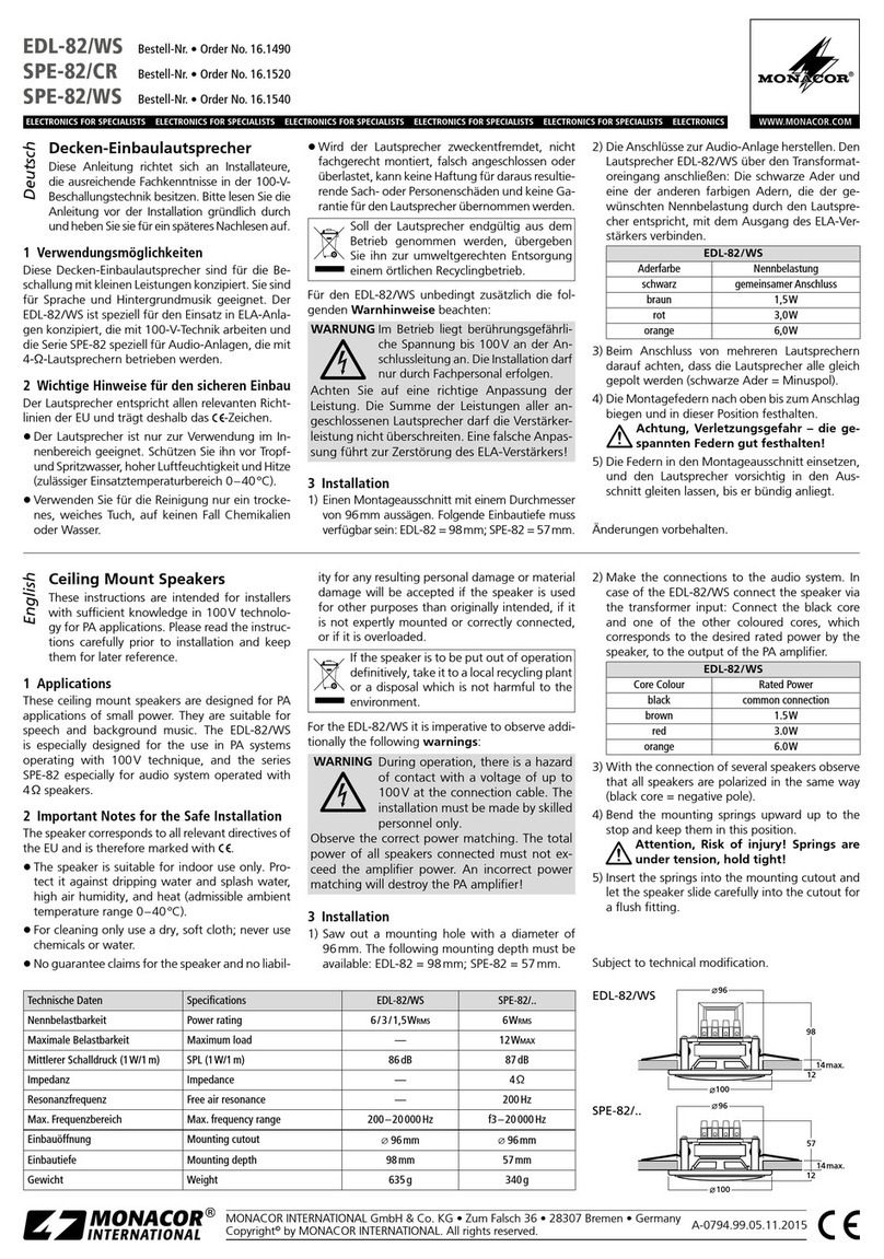
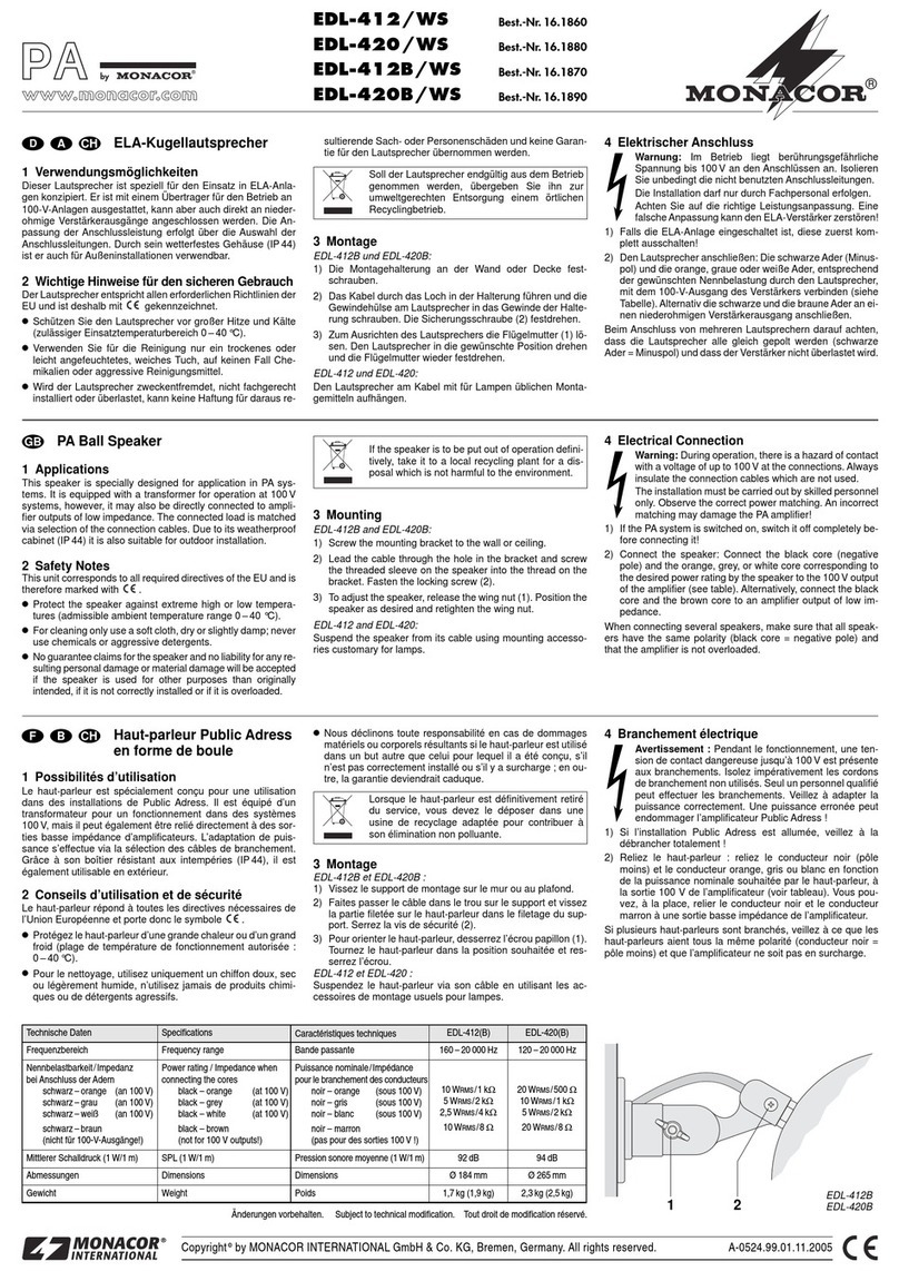
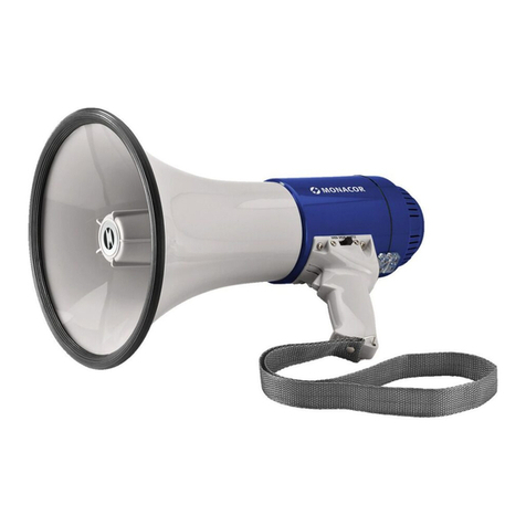
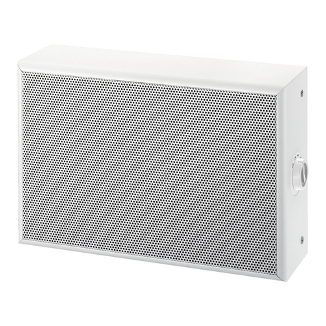
  9. Monacor ETS-422TW/WS User manual

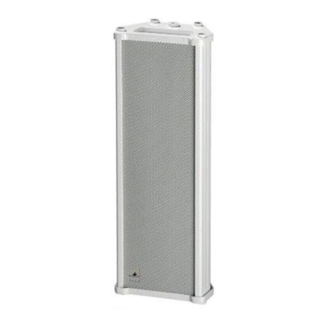
Monacor ETS-422TW/WS User manual

ELA-Tonsäule
Bitte lesen Sie diese Anleitung vor dem Betrieb gründ-
lich durch und heben Sie sie für ein späteres Nach-
lesen auf.
1 Verwendungsmöglichkeiten
Diese Lautsprechersäule ist speziell für den Einsatz in
ELA-Anlagen konzipiert. Sie ist mit einem Übertrager
für den Betrieb an 100-V-Anlagen ausgestattet. Die
Anpassung der Anschlussleistung erfolgt über die
Auswahl der Adern des Anschlusskabels. Als 2-Wege-
System ist die Tonsäule für Sprach- und Musikwieder-
gabe geeignet. Durch ihr wetterfestes Aluminium-
gehäuse (IP 66) ist sie auch für Außeninstallationen
verwendbar.
2 Wichtige Hinweise für den Gebrauch
Diese Tonsäule entspricht allen relevanten Richtlinien
der EU und ist deshalb mit gekennzeichnet.
GSchützen Sie die Tonsäule vor großer Hitze und
Kälte (zulässiger Einsatztemperaturbereich
-
20 °C
bis +50 °C).
GVerwenden Sie für die Reinigung nur ein trockenes
oder leicht angefeuchtetes, weiches Tuch, auf kei-
nen Fall Chemikalien oder aggressive Reinigungs-
mittel.
GWird die Tonsäule zweckentfremdet, nicht fachge-
recht montiert, falsch angeschlossen oder über-
lastet, kann keine Haftung für daraus resultierende
Sach- oder Personenschäden und keine Garantie
für die Tonsäule übernommen werden.
3 Montage
1) Die Wandhalterung an geeigneter Stelle fest-
schrauben. Der Pfeil an der Lautsprecherträger-
platte muss dabei nach oben zeigen.
2) Die Lautsprechersäule an der Halterung fest-
schrauben.
3) Zum Ausrichten der Lautsprechersäule die Fest-
stellschrauben für die Gelenke lösen.
Vorsicht! Die Lautsprechersäule gut festhalten,
bevor die Schraube des Gelenks für die Neigung
gelöst wird. Die Lautsprechersäule kippt sonst
nach unten, wodurch die Säule und die Wand be-
schädigt werden können.
Die Lautsprechersäule optimal ausrichten und die
Schrauben wieder gut festziehen.
Soll die Tonsäule endgültig aus dem Betrieb
genommen werden, übergeben Sie sie zur
umweltgerechten Entsorgung einem örtlichen
Recyclingbetrieb.
4 Elektrischer Anschluss
1) Falls die ELA-Anlage eingeschaltet ist, diese zuerst
komplett ausschalten!
2) Die Tonsäule anschließen: Die Adern des An-
schlusskabels für die gewünschte Nennleistung
(Tabelle) mit dem 100-V-Ausgang des Verstär-
kers verbinden.
Beim Anschluss von mehreren Tonsäulen oder ande-
ren Lautsprechern darauf achten, dass diese alle
gleich gepolt werden und dass der Verstärker nicht
überlastet wird.
Änderungen vorbehalten.
WARNUNG Im Betrieb liegt berührungsgefährliche
Spannung bis 100 V an der Anschluss-
leitung an.
Die Installation darf nur durch Fachper-
sonal erfolgen.
Isolieren Sie unbedingt die nicht benutzten Adern der
Lautsprecher-Anschlussleitung.
Achten Sie auf die Belastung des ELA-Verstärkers
durch die Lautsprecher. Eine Überlastung kann den
Verstärker beschädigen! Die Summe der Leistungen
aller angeschlossenen Lautsprecher darf die Verstär-
kerleistung nicht überschreiten.
PA Column Speaker
Please read these operating instructions carefully
prior to operating the unit and keep them for later
use.
1 Applications
This column speaker is specially designed for applica-
tion in PA systems. It is equipped with a transformer for
operation at 100 V systems. The connected load is
matched by selecting the cores of the connection
cable. As a 2-way system, the column speaker is suit-
able for speech and music reproduction. Due to its
weatherproof aluminium cabinet (IP 66) it can also be
used for outdoor installation.
2 Important Notes
This column speaker corresponds to all relevant direc-
tives of the EU and is therefore marked with .
GProtect the column speaker against extreme heat
and cold (admissible ambient temperature range
-
20 °C to +50 °C).
GFor cleaning only use a soft cloth, dry or slightly
damp; never use chemicals or aggressive deter-
gents.
GNo guarantee claims for the column speaker and no
liability for any resulting personal damage or mater-
ial damage will be accepted if the column speaker is
used for other purposes than originally intended, if it
is not correctly mounted or connected, or if it is over-
loaded.
3 Mounting
1) Fasten the wall bracket at a suitable place. Make
sure that the arrow on the plate supporting the
speaker is pointing upwards.
2) Screw the column speaker to the bracket.
3) To align the column speaker, release the screws
locking the joints.
Caution! Keep a good hold of the column speaker
before you release the screw to align the joint; oth-
erwise the column speaker will tilt over which may
damage both the column speaker and the wall.
Align the column speaker in an optimum way and
fasten the screws.
If the column speaker is to be put out of oper-
ation definitively, take it to a local recycling
plant for a disposal which is not harmful to the
environment.
4 Electrical Connection
1) If the PA system is switched on, switch it off com-
pletely before connecting it!
2) Connect the column speaker: Connect the cores of
the connection cable for the desired rated load
(table) to the 100 V output of the amplifier.
When connecting several column speakers or other
speakers, make sure that all speakers have the same
polarity and that the amplifier will not be overloaded.
Subject to technical modification.
WARNING During operation, there is a hazard of
contact with a voltage of up to 100 V at
the connection cable.
The installation must be made by
skilled personnel only.
Always insulate the cores of the speaker connection
cable that are not used.
Observe the load of the PA amplifier by the speakers.
An overload may damage the amplifier! The total
power of all speakers connected must not exceed the
amplifier power.
ETS-422TW/WS Best.-Nr. 16.3120
ETS-432TW/WS Best.-Nr. 16.3130
ETS-442TW/WS Best.-Nr. 16.3140
MONACOR INTERNATIONAL GmbH & Co. KG • Zum Falsch 36 • 28307 Bremen • Germany
Copyright©by MONACOR INTERNATIONAL. All rights reserved. A-1401.99.01.01.2013
®
GB
D A CH
Technische Daten Specifications ETS-422TW/WS ETS-432TW/WS ETS-442TW/WS
Frequenzbereich Frequency range 130 – 20 000 Hz 120 – 20 000 Hz 110 – 20 000 Hz
Nennbelastbarkeit (an 100 V)/Impedanz
bei Anschluss der Kabeladern
schwarz – rot
schwarz – weiß
schwarz – gelb
schwarz – braun
Power rating (at 100 V)/Impedance
when connecting the cores of the cable
black – red
black – white
black – yellow
black – brown
20 WRMS/500 Ω
10 WRMS/1 kΩ
5W
RMS /2 kΩ
2,5 WRMS /4 kΩ
30 WRMS/333 Ω
15 WRMS/667 Ω
7,5 WRMS/1,33 kΩ
3,75 WRMS/2,67 kΩ
40 WRMS/250 Ω
20 WRMS/500 Ω
10 WRMS/1 kΩ
5W
RMS/2 kΩ
Mittlerer Schalldruck (1 W/1 m) SPL (1 W/1 m) 92 dB 93 dB 93 dB
Anzahl der Breitbandlautsprecher + Hochtöner Number of full range speakers + tweeters 4 + 1 6 + 1 8 + 1
Abmessungen Dimensions 124 × 610 × 108 mm 124 × 813 × 108 mm 124 × 1016 × 108 mm
Gewicht Weight 4kg 5,6 kg 7,7 kg
Colonne sonore
Public Adress
Veuillez lire la présente notice avec attention avant
tout fonctionnement et conservez-la pour pouvoir vous
y reporter ultérieurement.
1 Possibilités dʼutilisation
Cette colonne sonore est spécialement conçue pour
une utilisation dans des installations de Public Adress.
Elle est équipée dʼun transformateur pour un fonction-
nement avec des installations 100 V. Lʼadaptation de
la puissance connectée sʼeffectue en sélectionnant
les conducteurs du câble de branchement. En tant que
système 2 voies, elle est adaptée pour la restitution de
discours et de musique. Grâce à son boîtier aluminium
résistant aux intempéries (IP 66), elle peut également
être utilisée en extérieur.
2 Conseils importants dʼutilisation
La colonne sonore répond à toutes les directives
nécessaires de lʼUnion européenne et porte donc le
symbole .
GProtégez la colonne des températures extrêmes
(chaleur et froid) [plage de température de fonction-
nement autorisée :
-
20 °C à +50 °C].
GPour nettoyer la colonne, utilisez uniquement un chif-
fon sec ou légèrement humidifié et doux, en aucun
cas de produits chimiques ou de produits abrasifs.
GNous déclinons toute responsabilité en cas de dom-
mages matériels ou corporels résultants si la colonne
sonore est utilisée dans un but autre que celui pour
lequel elle a été conçue, si elle nʼest pas correcte-
ment montée, branchée ou sʼil y a surcharge ; en
outre, la garantie deviendrait caduque.
3 Montage
1) Vissez le support mural à un endroit approprié. La
flèche sur la plaque supportant le haut-parleur doit
pointer vers le haut.
2) Vissez la colonne sur le support.
3) Pour orienter la colonne, desserrez les vis ver-
rouillant les articulations.
Attention ! Maintenez bien la colonne avant de
dévisser la vis de lʼarticulation pour lʼinclinaison : la
colonne peut basculer vers le bas, ce qui peut
endommager la colonne et le mur.
Orientez la colonne sonore de manière optimale et
serrez les vis.
Lorsque la colonne sonore est définitivement
retirée du service, vous devez la déposer dans
une usine de recyclage de proximité pour
contribuer à son élimination non polluante.
4 Branchement électrique
1) Si lʼinstallation Public Adress est allumée, veillez à
lʼéteindre avant dʼeffectuer les branchements !
2) Reliez la colonne sonore : reliez les conducteurs du
câble de branchement selon la puissance nominale
souhaitée (voir tableau) à la sortie 100 V de lʼam-
plificateur.
Si plusieurs colonnes ou dʼautres haut-parleurs sont
branchées, veillez à ce quʼelles aient toutes la même
polarité et que lʼamplificateur ne soit pas en surcharge.
Tout droit de modification réservé.
AVERTISSEMENT Pendant le fonctionnement, une
tension de contact dangereuse jus-
quʼà 100 V est présente au câble de
branchement. Seul un personnel
qualifié peut effectuer lʼinstallation !
Isolez toujours les conducteurs non utilisés du câble
haut-parleur.
Faites attention à la charge de lʼamplificateur PA par
les haut-parleurs. Une surcharge peut endommager
lʼamplificateur. La somme des puissances de lʼen-
semble des haut-parleurs reliés ne doit pas dépasser
la puissance de lʼamplificateur.
Colonna sonora PA
Vi preghiamo di leggere attentamente le presenti istru-
zioni prima della messa in funzione e di conservarle
per un uso futuro.
1 Possibilità dʼimpiego
Questa colonna sonora è stata realizzata special-
mente per lʼimpiego in impianti PA. È equipaggiata con
un trasformatore per impianti con uscita audio 100 V.
Lʼadattamento alla potenza di collegamento avviene
scegliendo i fili del cavo di collegamento. Come siste-
ma a 2 vie, la colonna sonora è adatta per la riprodu-
zione della lingua parlata e di musica. Grazie al conte-
nitore di alluminio, resistente alle intemperie (IP 66), è
utilizzabile anche per installazioni esterne.
2 Avvertenze importanti per lʼuso
Questa colonna sonora è conforme a tutte le direttive
rilevanti dellʼUE e pertanto porta la sigla .
GProteggere la colonna sonora da grande calore e
freddo (temperatura dʼimpiego ammessa fra
-
20 °C
a +50 °C).
GPer la pulizia usare solo un panno morbido, asciutto
o leggermente inumidito; non impiegare in nessun
caso prodotti chimici o detergenti aggressivi.
GNel caso dʼuso improprio, di montaggio non a regola
dʼarte, di collegamenti sbagliati o di sovraccarico
della colonna sonora, non si assume nessuna re-
sponsabilità per eventuali danni consequenziali a
persone o a cose e non si assume nessuna garan-
zia per la colonna.
3 Montaggio
1) Avvitare il supporto a parete in un punto adatto. La
freccia sulla piastra che porta lʼaltoparlante deve
essere rivolta in alto.
2) Avvitare la colonna sonora al supporto.
3) Per orientare la colonna sonora allentare le viti di
bloccaggio per gli snodi.
Attenzione! Tener ben ferma la colonna sonora
prima di allentare la vite dello snodo che permette
lʼinclinazione. Altrimenti la colonna si ribalta dan-
neggiando sia la colonna stessa che la parete.
Orientare la colonna sonora in modo ottimale e poi
stringere nuovamente bene le viti.
Se si desidera eliminare la colonna sonora de-
finitivamente, consegnarla per lo smaltimento
ad unʼistituzione locale per il riciclaggio.
4 Collegamento elettrico
1) Se lʼimpianto PA è acceso occorre dapprima spe-
gnerlo completamente!
2) Collegare la colonna sonora: collegare i fili del cavo
di collegamento secondo la potenza nominale ri-
chiesta (tabella) con lʼuscita audio dellʼamplifi-
catore.
Collegando più colonne sonore o altri altoparlanti, pre-
stare attenzione allʼidentica polarità per tutti e di non
sovraccaricare lʼamplificatore.
Con riserva di modifiche tecniche.
AVVERTIMENTO Durante il funzionamento, al cavo
di collegamento è presente una
tensione pericolosa fino a 100 V.
Lʼinstallazione deve essere fatta
solo da personale qualificato.
Isolare assolutamente i conduttori liberi del cavo di
collegamento dellʼaltoparlante.
Tener presente anche il carico dellʼamplificatore da
parte degli altoparlanti. Un sovraccarico può danneg-
giare lʼamplificatore! La somma delle potenze di tutti
gli altoparlanti collegati non deve superare la potenza
dellʼamplificatore.
ETS-422TW/WS Best.-Nr. 16.3120
ETS-432TW/WS Best.-Nr. 16.3130
ETS-442TW/WS Best.-Nr. 16.3140
MONACOR INTERNATIONAL GmbH & Co. KG • Zum Falsch 36 • 28307 Bremen • Germany
Copyright©by MONACOR INTERNATIONAL. All rights reserved. A-1401.99.01.01.2013
®
I
F B CH
Caractéristiques techniques Dati tecnici ETS-422TW/WS ETS-432TW/WS ETS-442TW/WS
Bande passante Banda passante range 130 – 20 000 Hz 120 – 20 000 Hz 110 – 20 000 Hz
Puissance nominale (sous 100 V)/Impédance
pour le branchement des conducteurs
noir – rouge
noir – blanc
noir – jaune
noir – marron
Potenza nominale (con 100 V)/Impedenza
collegando i fili del cavo
nero – rosso
nero – bianco
nero – giallo
nero – marrone
20 WRMS/500 Ω
10 WRMS/1 kΩ
5W
RMS /2 kΩ
2,5 WRMS /4 kΩ
30 WRMS/333 Ω
15 WRMS/667 Ω
7,5 WRMS/1,33 kΩ
3,75 WRMS/2,67 kΩ
40 WRMS/250 Ω
20 WRMS/500 Ω
10 WRMS/1 kΩ
5W
RMS/2 kΩ
Pression sonore moyenne (1 W
/
1m)
Pressione sonora media (1 W/1 m) 92 dB 93 dB 93 dB
Nombre de HPs large bande + HPs dʼaigu Numero altoparlanti a larga banda + tweeter 4 + 1 6 + 1 8 + 1
Dimensions Dimensioni 124 × 610 × 108 mm 124 × 813 × 108 mm 124 × 1016 × 108 mm
Poids Peso 4kg 5,6 kg 7,7 kg
Columna acústica profesional
Por favor lea atentamente estas instrucciones de fun-
cionamiento antes de utilizar el aparato y guárdelas
para su utilización posterior.
1 Aplicaciones
Esta columna acústica está especialmente diseñada
para su aplicación en sistemas profesionales. Está
equipada con un transformador para funcionar en sis-
temas de 100 V. La carga conectada se hace coincidir
seleccionando los conductores del cable de conexión.
Como sistema de 2 vías, la columna acústica está
adecuada para reproducciones musicales y de voz/
canto. Gracias a su recinto impermeable en aluminio
(IP 66) también puede instalarse en exteriores.
2 Notas de Importancia
Esta columna acústica cumple con todas las directi-
vas relevantes por la UE y por lo tanto está marcada
con el símbolo .
GProteja la columna acústica contra temperaturas
extremas (temperatura ambiente admisible
-
20 °C
a +50 °C).
GPara su limpieza utilice un paño limpio y seco o lige-
ramente húmedo; no utilice nunca productos quími-
cos ni detergentes agresivos.
GNo podrá reclamarse ninguna garantía por la co-
lumna acústica ni responsabilidad alguna por cual-
quier daño personal o material si se utiliza la colum-
na acústica para otros propósitos diferentes a los
originalmente concebidos, si no se monta o conec-
ta correctamente o se está sobrecargada.
3 Montaje
1) Fije el soporte de pared en un lugar adecuado.
Asegúrese de que la flecha de la placa que soporta
el altavoz mira hacia arriba.
2) Atornille la columna acústica al soporte.
3) Para alinear la columna acústica, afloje los tornillos
que bloquean las juntas.
¡Precaución! Sujete la columna acústica firme-
mente antes de aflojar el tornillo para alinear la
junta, de lo contrario la columna acústica se caerá
y podría dañarse o dañar la pared.
Alinee la columna acústica del mejor modo y fije los
tornillos.
Si la columna acústica va a ponerse fuera de
servicio definitivamente, llévela a la planta de
reciclaje más cercana para una disposición
no perjudicial para el medioambiente.
4 Conexión eléctrica
1) ¡Si el sistema está conectado, desconéctelo com-
pletamente antes de la conexión!
2) Conecte la columna acústica: Conecte los conduc-
tores del cable de conexión para la carga deseada
(tabla) a la salida de 100 V del amplificador.
Cuando conecte varias columnas acústicas u otros
altavoces, asegúrese de que todos tienen la misma
polaridad y que el amplificador no está sobrecargado.
Sujeto a modificaciones técnicas.
ADVERTENCIA Durante el funcionamiento existe el
peligro de contacto con un voltaje de
hasta 100 V en el cable de conexión.
La instalación debe hacerse sólo el
personal cualificado.
Aísle siempre los conductores del cable de conexión
de altavoz que no se utilizan.
Observe la carga del amplificador de megafonía en
los altavoces. Una sobrecarga puede dañar el ampli-
ficador. La potencia total de todos los altavoces
conectados no puede sobrepasar la potencia del
amplificador.
Kolumna głośnikowa PA
Przed rozpoczęciem użytkowania prosimy o zapozna-
nie się z instrukcją i zachowanie jej do wglądu.
1 Zastosowanie
Kolumna głośnikowa jest przeznaczona do zastoso-
wania w systemach PA. Wyposażona jest w transfor-
mator pracujący w systemie 100 V. Za pomocą prze-
łącznika obrotowego można wybrać żądane obciąże-
nie znamionowe. Dwudrożna kolumna głośnikowa
przystosowana jest do odtwarzania komunikatów
słownych oraz muzyki. Dzięki wodoodpornej aluminio-
wej obudowie (IP 66) może być stosowana w instala-
cjach zewnętrznych.
2 Bezpieczeństwo użytkowania
Ponieważ kolumna głośnikowa spełnia wszelkie wy-
magania norm obowiązujących w Unii Europejskiej,
została oznaczona symbolem .
GNależy chronić kolumnę głośnikową przed ekstre-
malnie wysokimi i niskimi temperaturami (dopusz-
czalny zakres temperatur wynosi
-
20 °C do +50 °C).
GDo czyszczenia urządzenia należy używać suchej,
miękkiej tkaniny. Nie wolno stosować wody ani che-
micznych środków czyszczących.
GProducent ani dostawca nie ponoszą odpowiedzial-
ności za wynikłe szkody (uszkodzenie sprzętu lub
obrażenia użytkownika), jeśli urządzenie używano
niezgodnie z przeznaczeniem, nieprawidłowo za-
montowano lub podłączono, bądź przeciążono.
3 Montaż
1) Przymocować uchwyt w odpowiednim miejscu na
ścianie. Upewnić się, że strzałka na płytce podtrzy-
mującej skierowana jest w górę.
2) Przykręcić kolumnę do uchwytu.
3) Aby uzyskać żądane ustawienie, poluzować śruby
blokujące na przegubie kulowym.
Uwaga! Przed poluzowaniem śrub, przytrzymać
kolumnę; w przeciwnym razie może nastąpić jej
obrócenie i uszkodzenie zarówno głośnika jak i
ściany.
Ustawić kolumnę w żądanej pozycji i dokręcić
śruby blokujące.
Po całkowitym zakończeniu eksploatacji ur-
ządzenia należy oddać je do punktu utylizacji
odpadów, aby uniknąć zanieczyszczenia śro-
dowiska naturalnego.
4 Połączenie elektryczne
1) Jeżeli wzmacniacz jest włączony, należy go wyłą-
czyć przed przystąpieniem do podłączania!
2) Podłączyć kolumnę głośnikową: połączyć żyłami
kabla odpowiednie odczepy (tabela) z wyjściem
100 V wzmacniacza.
Przy podłączaniu kilku kolumn głośnikowych należy
zwrócić uwagę aby wszystkie miały jednakową biegu-
nowość i żeby wzmacniacz nie był przeciążony.
Z zastrzeżeniem możliwości zmian.
UWAGA W trakcie pracy głośnika, na przyłącz-
ach może występować niebezpieczne
dla życia napięcie o wartości do 100 V.
Instalację może przeprowadzać tylko
przeszkolony personel.
Należy zaizolować nie podłączone końcówki kabla
połączeniowego.
Szczególną uwagę należy zwrócić na odpowiedni
dobór mocy wzmacniacza do mocy głośników. Nie-
dopasowanie mocowe może spowodować przecią-
żenie wzmacniacza i w konsekwencji jego uszkodze-
nie. Sumaryczna moc głosników, nie może przekra-
czać mocy wzmacniacza.
ETS-422TW/WS Best.-Nr. 16.3120
ETS-432TW/WS Best.-Nr. 16.3130
ETS-442TW/WS Best.-Nr. 16.3140
MONACOR INTERNATIONAL GmbH & Co. KG • Zum Falsch 36 • 28307 Bremen • Germany
Copyright©by MONACOR INTERNATIONAL. All rights reserved. A-1401.99.01.01.2013
®
PL
E
Características técnicas Dane techniczne ETS-422TW/WS ETS-432TW/WS ETS-442TW/WS
Rango de frecuencia Pasmo przenoszenia 130 – 20 000 Hz 120 – 20 000 Hz 110 – 20 000 Hz
Índice de potencia (a 100 V)/Impedancia
cuando conecte los conductores
negro – rojo
negro – blanco
negro – amarillo
negro – marrón
Moc znamionowa (tryb 100 V)/Opór
przy podłączaniu rdzeni
czarny – czerwona
czarny – biały
czarny – żółty
czarny – brązowa
20 WRMS/500 Ω
10 WRMS/1 kΩ
5W
RMS /2 kΩ
2,5 WRMS /4 kΩ
30 WRMS/333 Ω
15 WRMS/667 Ω
7,5 WRMS/1,33 kΩ
3,75 WRMS/2,67 kΩ
40 WRMS/250 Ω
20 WRMS/500 Ω
10 WRMS/1 kΩ
5W
RMS/2 kΩ
Nivel de presión del sonido (1 W/1 m) SPL (1 W/1 m) 92 dB 93 dB 93 dB
Número de altavoces “full range” + tweeters Ilość głośników pełnopasmowych + wysokoton 4 + 1 6 + 1 8 + 1
Dimensiones Wymiary 124 × 610 × 108 mm 124 × 813 × 108 mm 124 × 1016 × 108 mm
Peso Waga 4kg 5,6 kg 7,7 kg

This manual suits for next models

5

Other Monacor Speakers manuals

Monacor TM-25 User manual

Monacor

Monacor TM-25 User manual

Monacor ESP-360/WS User manual

Monacor

Monacor ESP-360/WS User manual

Monacor EDL-24 User manual

Monacor

Monacor EDL-24 User manual

Monacor IT-100RTW User manual

Monacor

Monacor IT-100RTW User manual

Monacor EDL-606 User manual

Monacor

Monacor EDL-606 User manual

Monacor IRS-200TXA User manual

Monacor

Monacor IRS-200TXA User manual

Monacor EDL-82/CR User manual

Monacor

Monacor EDL-82/CR User manual

Monacor ETS-410TW/WS User manual

Monacor

Monacor ETS-410TW/WS User manual

Monacor ESP-5U User manual

Monacor

Monacor ESP-5U User manual

Monacor TM-17 User manual

Monacor

Monacor TM-17 User manual

Monacor ETS-317/WS User manual

Monacor

Monacor ETS-317/WS User manual

Monacor SPE-230BT Quick guide

Monacor

Monacor SPE-230BT Quick guide

Monacor ETS-210TW User manual

Monacor

Monacor ETS-210TW User manual

Monacor EUL-26/SW User manual

Monacor

Monacor EUL-26/SW User manual

Monacor ETS-120 SL/WS User manual

Monacor

Monacor ETS-120 SL/WS User manual

Monacor IT-100TW User manual

Monacor

Monacor IT-100TW User manual

Monacor EDL-530EN/SW User manual

Monacor

Monacor EDL-530EN/SW User manual

Monacor TM-45 User manual

Monacor

Monacor TM-45 User manual

Monacor EDL-42HQ User manual

Monacor

Monacor EDL-42HQ User manual

Monacor IT-200TW User manual

Monacor

Monacor IT-200TW User manual

Monacor EDL-204 User manual

Monacor

Monacor EDL-204 User manual

Monacor EDL-65TW User manual

Monacor

Monacor EDL-65TW User manual

Monacor PAB-82WP User manual

Monacor

Monacor PAB-82WP User manual

Monacor 0163450 User manual

Monacor

Monacor 0163450 User manual

Popular Speakers manuals by other brands

JBL CLIP+ quick start guide

JBL

JBL CLIP+ quick start guide

D.A.S. ARTEC 500 Series user manual

D.A.S.

D.A.S. ARTEC 500 Series user manual

TimoLabs TM-BT003S-2016C user manual

TimoLabs

TimoLabs TM-BT003S-2016C user manual

Somogyi Elektronic SAL PAX 225 instruction manual

Somogyi Elektronic

Somogyi Elektronic SAL PAX 225 instruction manual

Clark Synthesis TACTILE SOUND AQ339 Aquasonic Specifications

Clark Synthesis

Clark Synthesis TACTILE SOUND AQ339 Aquasonic Specifications

TOPPOINT LT91290 manual

TOPPOINT

TOPPOINT LT91290 manual

PROEL FLASH12A user manual

PROEL

PROEL FLASH12A user manual

JBL ES10BK owner's guide

JBL

JBL ES10BK owner's guide

Vonyx TX Series instruction manual

Vonyx

Vonyx TX Series instruction manual

JBL Cinema SB300 Specifications

JBL

JBL Cinema SB300 Specifications

WOOX FX25/12 Service manual

WOOX

WOOX FX25/12 Service manual

Steren BAF-1596 instruction manual

Steren

Steren BAF-1596 instruction manual

Miiego MiiBLASTER quick start guide

Miiego

Miiego MiiBLASTER quick start guide

JBL S3100 MKII R/L Technical manual

JBL

JBL S3100 MKII R/L Technical manual

KEF Uni-Q FLC 2003 Brochure & specs

KEF

KEF Uni-Q FLC 2003 Brochure & specs

MUZEN ORIGINAL III R303I manual

MUZEN

MUZEN ORIGINAL III R303I manual

Zoomax Acesight VR user guide

Zoomax

Zoomax Acesight VR user guide

Philips SBT50/00 user manual

Philips

Philips SBT50/00 user manual

manuals.online logo
manuals.online logoBrands
  • About & Mission
  • Contact us
  • Privacy Policy
  • Terms and Conditions

Copyright 2025 Manuals.Online. All Rights Reserved.