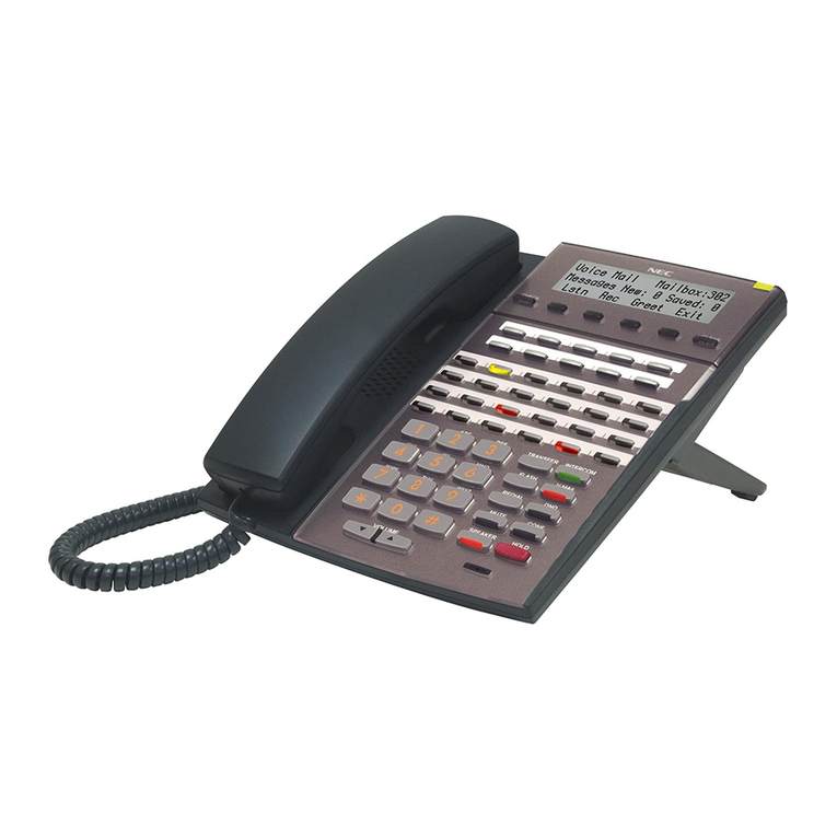
NEC SL1000 User manual

Please read this manual carefully before installing this product and save this manual for future use.
This guide explains the installation, configuration and operation of the SL1000 Telephone System including
the Outside (CO) line and telephone connections.
This Getting Started Guide will cover the most frequently used configuration options. Only the SL1000 Main
KSU is included, it does not cover optional items.
For more advanced configuration, refer to Hardware Manual (separate issue) for the details.
(IP4WW-1632M-A KSU)
Getting Started Guide
Issue 1.0 (January. 2011)
A50-031579-001

SL1000 Getting Started Guide
Table of Contents
IMPORTANT INFORMATION.............................................................................................................................. 1
REGULATORY................................................................................................................................................ 3
WHAT IS THE SL1000?.................................................................................................................................. 5
OUTSIDE LINES .......................................................................................................................................... 5
SL1000 SYSTEM MULTI-LINE TELEPHONES ................................................................................................. 6
ANALOG TELEPHONES................................................................................................................................7
SYSTEM CONNECTION DIAGRAM................................................................................................................. 7
OPTIONAL ITEMS........................................................................................................................................ 8
BEFORE INSTALLATION................................................................................................................................10
INSTALLATION PROCEDURE....................................................................................................................... 10
UNPACKING ............................................................................................................................................. 10
UNPACKING ..............................................................................................................................................11
NECESSARY TOOLS (NOT SUPPLIED) .........................................................................................................11
REPLACING AN EXISTING TELEPHONE SYSTEM ...........................................................................................11
INSTALLATION ............................................................................................................................................. 12
WALL MOUNT THE SL1000 SYSTEM .......................................................................................................... 13
CONNECTING EARTH GROUND.................................................................................................................. 14
CONNECTING EXTENSIONS....................................................................................................................... 15
MULTI-LINE TELEPHONE LEG ADJUSTMENT ............................................................................................ 16
WALL MOUNTING THE MULTI-LINE TELEPHONE....................................................................................... 17
CONNECTING OUTSIDE (CO) LINES .......................................................................................................... 18
SECURING CABLES .................................................................................................................................. 19
CONNECTING POWER &STARTING UP THE SL1000 SYSTEM...................................................................... 20
1. BEFORE STARTING UP THE SYSTEM .................................................................................................. 20
2. START UP THE SYSTEM..................................................................................................................... 21
TEST THE SYSTEM ................................................................................................................................... 22
1. TEST THE SL1000 MULTI-LINE TELEPHONES (TEST EACH PHONE IN TURN.) ......................................... 22
2. TEST THE ANALOG TELEPHONES (TEST EACH PHONE IN TURN.) ........................................................... 22
3. TEST THE OUTSIDE (CO) LINES (TEST EACH LINE IN TURN.) ................................................................ 23
INSTALL OPTIONAL UNITS AND EQUIPMENTS .............................................................................................. 23
POWER FAILURE OPTIONS........................................................................................................................ 24
1. POWER FAILURE SETTING USE SL1000 SYSTEM ................................................................................ 24
2. PLUG A ANALOG TELEPHONE DIRECTORY CONNECT TO THE OUTSIDE(CO) LINE SOCKET....................... 25
3. USE THE EXTERNAL BACKUP BATTERY BOX(OPTION)TO CONNECT EACH KSU .................................... 25
CONFIGURE THE SL1000 ............................................................................................................................ 26
ENTERING THE TELEPHONE PROGRAMMING MODE .................................................................................... 27
1. HOW TO ENTERING THE PROGRAMMING MODE ................................................................................... 27
2. SELECTING THE PROGRAMMING NUMBER .......................................................................................... 27
3. EXITING THE PROGRAMMING MODE ................................................................................................... 27
4. USING THE SYSTEM PHONE KEYS TO MAKE CHANGES FROM PROGRAMMING MODE.............................. 28
TIME &DATE SETTING .......................................................................................................................... 29
TELEPHONE RINGING ASSIGNMENT ....................................................................................................... 29
EXAMPLE CONFIGURATION.................................................................................................................... 33
TELEPHONE RING STYLE ...................................................................................................................... 34
INTERNAL CALL RINGING MODE............................................................................................................. 35
EXTENSION NAME ................................................................................................................................35
OUTGOING EXCHANGE LINE ACCESS..................................................................................................... 36
CALLER ID ........................................................................................................................................... 38
RECALL FOR ANALOG TELEPHONES....................................................................................................... 39
DEPARTMENT (EXTENSION)GROUPS..................................................................................................... 40
CREATE AN INTERNAL PAGING GROUP ................................................................................................... 43
SL1000 Getting Started Guide
1
Important Information
Please read following instructions carefully and save these instructions.
When using your Telephone System, basic safety precautions should always be followed to reduce
the risk of fire, electric shock and injury to persons, including the following.
【DANGER】-Incorrect use of the equipment may cause personal injury or death.
☛ IF DAMAGE TO THE UNIT EXPOSES ANY INTERNAL PARTS, DISCONNECT THE
POWER SUPPLY CORD IMMEDIATELY AND RETURN THE UNIT TO YOUR
SUPPLIER.
☛ THIS UNIT IS EQUIPPED WITH AN EARTHED TERMINAL. FOR SAFETY REASONS
THIS PLUG MUST ONLY BE CONNECTED TO AN EARTHED OUTLET THAT HAS
BEEN INSTALLED ACCORDING TO APPLICABLE REGULATIONS.
☛ TO PREVENT POSSIBLE FIRE OR ELECTRIC SHOCK, DO NOT EXPOSE THIS
PRODUCT TO RAIN OR ANY TYPE OF MOISTURE.
☛ THE POWER SUPPLY CORD ON THIS EQUIPMENT MUST BE USED TO DISCONNECT
THE MAIN POWER. ENSURE THAT THE AC OUTLET IS LOCATED NEAR THE
EQUIPMENT AND IS EASILY ACCESSIBLE.
☛ DISCONNECT ALL POWER TO THE EQUIPMENT BEFORE COVER(S) ARE REMOVED.
☛DO NOT TOUCH THE INTERNAL PARTS OF THE MAIN EQUIPMENT TO
DISASSEMBLY OR CONFIGURE IT. THIS ACTION MAY CAUSE A FIRE, AN
ELECTRICAL SHOCK OR A SYSTEM FAILURE.
NEC CORPORATION DOES NOT TAKE ANY RESPONSIBILITY FOR DISASSEMBLED
OR RECONFIGURED EQUIPMENT.
【WARNING】-Incorrect use of the equipment may cause personal injury or a serious system
fault.
☛TO AVOID SHOCK OR DAMAGE, DO NOT PLUG IN OR TURN THE SYSTEM POWER
ON BEFORE COMPLETING THE INSTALLATION PROCESS.
☛ AVOID USING A TELEPHONE SYSTEM DURING ELECTRICAL STORM.
☛ USE ONLY COMMERCIAL AC POWER TO PREVENT SHOCK OR FIRE.
☛ DO NOT USE THIS PRODUCT IN PLACE WHERE WATER OR OTHER FLUIDS COMES
IN CONTACT WITH THE EQUIPMENT.
☛ TO PROTECT THIS UNIT FROM STATIC ELECTRICITY, DO NOT TOUCH ANY
EXTERNAL CONNECTORS OF THE UNIT.
☛ IF LIGHTNING CAUSES A FAULT, CONTACT THE DEALER.
☛WHEN RELOCATING THE EQUIPMENT, FIRST DISCONNECT THE TELECOM

SL1000 Getting Started Guide
2
CONNECTION BEFORE DISCONNECTING THE POWER CONNECTION. WHEN THE
UNIT IS INSTALLED IN THE NEW LOCATION, RECONNECT THE POWER FIRST,
AND THEN RECONNECT THE TELECOM CONNECTION.
【ATTENTION】-Incorrect use of the equipment may limit the system performance or cause
the system to fail.
☛THE TELEPHONE SYSTEM CAN ONLY BE USED IN NEC-DESIGNATED COUNTRIES.
☛IF THE SYSTEM REQUIRES INSTALLATION OR REPAIR, CONTACT THE DEALER OR
ITS SERVICE TECHNICIAN.
☛FOR THE PERIODIC-REPLACEMENT PARTS OR OPTION PRODUCTS, PLEASE ASK
YOUR SUPPLIER.
☛BE SURE TO CHECK WITH YOUR SUPPLIER BEFORE YOU TRANSPORT OR MOVE
THIS SYSTEM. IF THE SYSTEM IS MOVED WITHOUT CHECKING WITH SUPPLIER
THE SYSTEM MAYBE DAMAGE OR SYSTEM MAY NOT WORK PROPERLY.
☛THE GOAL IS TO PRODUCE A COMPREHENSIVE AND ACCURATE MANUAL.
HOWEVER, IF ERRORS OR OMISSIONS ARE FOUND IN THIS MANUAL, PLEASE
NOTIFY NEC AUTHORIZED SUPPLIER.

SL1000 Getting Started Guide
3
Regulatory
Battery Disposal
The SL1000 system includes the batteries listed below. When disposing of these batteries, KSU, and/or
Unit, you must comply with applicable federal and state regulations regarding proper disposal procedures.
Unit Name Type of Battery Quantity
IP4( )-CPU-A1 Lithium 1
External Battery
(IP4WW-Battery Box)
Sealed Lead 2 per IP4WW-Battery Box
The SL1000 IP4( )-CPU-A1 provides memory backup for approximately three years. The
Lithium battery should be replaced every two years.
IMPORTANT SAFEGUARDS FOR BATTERY DISPOSAL
DO NOT PLACE USED BATTERIES IN YOUR REGULAR TRASH! THE PRODUCT YOU
PURCHASED CONTAINS LITHIUM, SEALED LEAD BATTERIES. LITHIUM, SEALED LEAD
BATTERIES MUST BE COLLECTED, RECYCLED, OR DISPOSED OF IN AN ENVIRONMENTALLY
SOUND MANNER.
The incineration, landfilling or mixing of sealed lead batteries with the municipal solid waste stream is
PROHIBITED BY LAW in most areas. Contact your local solid waste management officials for other
information regarding the environmentally sound collection, recycling, and disposal of the battery.
Sealed lead batteries must be returned to a federal or state approved sealed lead battery recycler. This
may be where the batteries were originally sold or a local seller of automotive batteries. Contact your local
waste management officials for other information regarding the environmentally sound collection, recycling
and disposal of the battery contained in this product.
The packaging for the SL1000 system contains the following labels regarding proper disposal.
EUROPEAN UNION INFORMATION Notice to the user
The system described in this manual is intended to be connected to analog and digital networks and
supports a wide range of peripheral equipment. The following interfaces are available for connection to
public analog and digital telecommunication networks:
TBR3 ISDN basic rate interface
TBR4 ISDN primary rate interface
ES203-021 Analogue interface
To take advantage of all features of this system and the connected equipment, the country or network
specific features should match the supported features of the system. For an overview of the supported
features, refer to the detailed documentation that comes with this system, contact your local NEC Unified
Solutions representative or the support desk of NEC Unified Solutions.
Declaration of conformity
Hereby, NEC Unified Solutions, declares that the SL1000 is in compliance with the essential requirements
and other relevant provisions of Directive 1999/5/EC.
For the Declaration of Conformity, visit:
http://www.nec-unified.com/doc

SL1000 Getting Started Guide
4
Electromagnetic Compatibility
For the SL1000 system the following warning is applicable:
Warning
This is a class A product. In a domestic environment this product may cause radio interference in which
case the user may be required to take adequate measures.
PRODUCT DISPOSAL INFORMATION
For Countries in the European Union
The symbol depicted here has been affixed to your product to inform you that
electrical and electronic products should not be disposed of as municipal waste.
Electrical and electronic products including the cables, plugs and accessories
should be disposed of separately to allow proper treatment, recovery and recycling.
These products should be taken to a designated facility where the best available
treatment, recovery and recycling techniques are available. Separate disposal has
significant advantages: valuable materials can be re-used and it prevents the
dispersion of unwanted substances into the municipal waste stream. This
contributes to the protection of human health and the environment.
Please be informed that a fine may be imposed for illegal disposal of electrical and
electronic products via the general municipal waste stream.
To facilitate separate disposal and environmentally sound recycling arrangements have been made for
local collection and recycling. If your electrical and electronic products must be disposed of please refer to
your supplier or the contractual agreements that your company has made upon acquisition of these
products.
At www.nec-unified.com/weee you can find information about separate disposal and environmentally
sound recycling.
Battery information
Defective or exhausted batteries should never be disposed of as municipal waste. Return old batteries to
the battery supplier, a licensed battery dealer or a designated collection facility. Do not incinerate batteries.
This product uses Lithium batteries. Do not use any other type.
For an overview of the location of batteries used in these systems, the battery replacement or removal
instructions, please refer to the SL1000 System Hardware Manual.

SL1000 Getting Started Guide
5
What is the SL1000?
The SL1000 system consists of a main KSU with a base board
pre-installed.
The SL1000 telephone system will allow the connection of up to four
exchange lines plus eight telephones. The eight telephones can be either
SL1000 system telephones or Analog telephones.
Also Built-in Answering Machine (1ch) is initially equipped.
It can accommodate optional parts to expand the system or connect ISDN
BRI /PRI lines and IP trunk lines.
Further more, there are optional expansion KSU/units available to
increase the number of exchange lines and telephones that can be
connected.
All equipment will operate when the SL1000 is installed as shown in this
guide, it is not necessary to make any changes to the system
configuration.
Calls received on the exchange lines will ring at telephone number 200 (Extension Port No.1).
With the default settings:
Each telephone will function and is assigned an extension number.
Each telephone can make outside calls by dialing 9 (Trunk Access Code).
Each exchange line is presented at a Function Key with busy lamp indication.
Outside lines
You can connect up to four analog trunk lines to the SL1000 KSU (IP4WW-1632M-A1).
The trunk lines must be loop start type.
The SL1000 system will also detect Caller ID sent by the Network Provider.
Each line is connected via a RJ11 4-way socket. The exchange lines are supplied by your Network Provider.

SL1000 Getting Started Guide
6
SL1000 System Multi-line Telephones
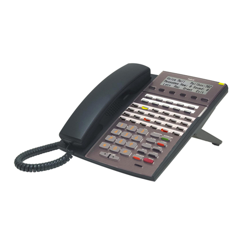
There are two types of SL1000 System Multi-lineTelephones available.
IP4WW-12TXH-A TEL IP4WW-24TXH-A TEL
Terminal Type Hybrid (4Wire)
Multi-Line Terminal
Hybrid (4Wire)
Multi-Line Terminal
Connected to Hybrid Extension Port Hybrid Extension Port
Color Line-Up Black/White Black/White
LCD 16 digits x 2 lines
w/o Backlit
16 digits x 2 lines
w/o Backlit
Programmable Keys 12
(BLF : Red/Green)
24
(BLF : Red/Green)
Soft Keys No No
Menu Cursor Key Yes Yes
Incoming LED 2 colors
(Red/Green)
2 colors
(Red/Green)
Handsfree Half-duplex Half-duplex
Backlit Dial Pad No No
Headset Port No
(use Handset Port)
No
(use Handset Port)
Angle Adjustment 2-steps 2-steps
Wall Mounting Kit Built-In Built-In
You can connect up to 8 SL1000 system Multi-line telephones to any of the station connections. (If you need
more telephones you will need to install optional cards). The SL1000 system Multi-line telephones have
illuminated function keys that can be tailored to your own requirements.
The SL1000 system Multi-line telephones have a LCD display will show information about who is calling you, the
call you are on or the feature you are using.
Each Multi-line telephone is connected to the SL1000 system via a RJ11 4-way socket. The cables are
supplied with the telephone.
There is also a SL1000 DSS Consoles available; this gives busy lamp indication and can be installed alongside
a System Multi-line telephone for use by system operator (DSS console takes one hybrid station port).
IP4WW-60D-A DSS
Terminal Type Hybrid (4Wire)
DSS Console
Connected to Ext. Port No.8
at each card
Color Line-Up Black/White
Programmable Keys 60
(BLF : Red/Green)
Angle Adjustment 2-steps (Base)
Wall Mounting Kit Built-In

SL1000 Getting Started Guide
7
Analog Telephones
You can connect up to 8 analog telephones or Analog cordless phones to any of the station connections.
The telephones can be dial pulse or DTMF dialing.
They can have Hook Flash or Timed Break Recall.
The SL1000 can send Caller ID to the analog telephone.
System Connection Diagram
The diagram shows system connection diagram.
P
PS
ST
TN
N
IP/VoIP
ISDN
DSS
Analog Telephone
FAX
DoorBox
Door Opener
External Music Source
External Paging System
CTI Server
PC
PCPro/Web Pro
Backup Battery
Printer
Remote PC
Hybrid Port Office LAN/ CTI
Analog Trunk Port
Embedded
VRS/VM
KSU2
KSU3 KSU4
KSU1
Relay Control Port
TEL
Expanded

SL1000 Getting Started Guide
8
Up to 4 Trunk lines and 8 extensions (SL1000 system Multi-line Telephone, Analog Telephone including FAX
and Analog Cordless phone) can be connected.
Optional Items
Items Description Outline
1632ME-A EXP SL1000 Expansion cabinet to increase the system
capacity.
Up to three SL1000 Expansion KSU’s can be
connected to the SL1000 Main KSU.
IP4WW-Battery Box This is the external backup battery box to supply the
DC power to the system when the AC power is
failed. It is connected to the power supply for each
KSU. The battery itself must be prepared by local
supplier.
IP4WW-MEMDB-C1 This card provides additional expansion memory
Interface. Install onto the CPU card (MEMDB slot)
at main KSU. Following features need this card:
• Expansion KSU(s)
• VoIP
• CTI
• Remote Upgrade (main software)
• VRS/InMail Channel Control
IP4WW-VOIPDB-C1
<Feature Available> This card provides Voice over IP operation for IP
trunks and extensions.
• Install this card onto the CPU card (VoIPDB slot)
at main KSU.
PZ-VM21 This card provides additional Voice Recording
Service and Voice Mail Service.
• Install onto the CPU card (VMDB slot) within the
SL1000 Main KSU.
• Compact flash card determines the features
available.

SL1000 Getting Started Guide
9
IP4WW-408E-A1 • Trunk & Station expansion interface card
• Installed into SL1000 Main KSU.
• Provides 4 analog trunks and 8 hybrid extension
ports (1 port can be used for Power Failure, Refer to
Power Failure feature within this guide)
IP4WW-008E-A1 • Station expansion interface card.
• Installed into SL1000 Main KSU.
• Provides 8 hybrid extension ports
• The 2BRIDB card can also be mounted onto this
card.
IP4WW-000E-A1 • Does not provide any Trunk or Station ports.
• Used only when the 2BRIDB card is required
without the need to add additional trunk or station
ports.
IP4WW-1PRIU-C1 • ISDN Primary Rate Interface, T1 interface or E1
Interface.
• Installed into SL1000 Main KSU.
• Provides 1 ISDN PRI circuit.
IP4WW-2BRIDB-C1 • ISDN Basic Rate interface.
• Mounted onto the IP4WW-008E-A1 or
IP4WW-408E-A1 card.
• Provides 2 ISDN BRI circuits.
IP4WW-EXIFB-C1 • Allows connection of up to 3 Expansion KSUs to
the Main KSU.
• Installed into the SL1000 Main KSU.
• CAT5 connection cable is supplied with the
SL1000 Expansion KSU.
IP4WW-CFVRS-C1 Compact Flash card for VRS.
• 512MB, Compact Flash card mounted onto the
PZ-VM21 card within the SL1000 Main KSU.
• Provides 4 channels and 15 hour recording capacity.
IP4WW-CFVMS-C1 Compact Flash card for VRS plus voice mail
• 512MB, Compact Flash card mounted onto the
PZ-VM21 card within the SL1000 Main KSU.
• Provides 2 channels and 15 hour recording capacity.
IP4WW-CFVML-C1 Compact Flash card for VRS plus voice mail
• 1GB, Compact Flash card mounted onto the PZ-VM21
card within the SL1000 Main KSU.
• Provides 4 channels and 40 hour recording capacity.
DP-D-1( )
Or equivalent
Doorphone unit with call button, microphone and
loudspeaker.
• Provides customer calling feature at an entry door.
• Connects to one of the analog station ports on the
SL1000 Main KSU.
IP4WW-24TIXH-C TEL
<Feature Available> This is Multi-line IP Telephone.
• Connects to the VOIPDB.
System Feature
License
Certain features can be enabled by adding a
license key.
• Increase VoIP channels and features.
• Increase Voice Mail channels.
• Enable Mobile Extension.
• Enable Hotel/Motel feature
-

SL1000 Getting Started Guide
10
Before Installation
Installation Procedure
1. Unpack all items and
check for damaged o
r
missing parts.
2. Are you are replacing an
existing telephone system
(Aspila Topaz, Xn120 o
r
IPC100) ???
3. Mount the SL1000 system
on the wall.
4. Connect the Telephones.
5. Connect the Trunk Lines.
8. Connect the AC Cord and
Switch on the SL1000 system.
9. Test the System.
7. Secure the Cables.
10. Configure the SL1000
System to the customer’s
requirements.
11. Install Optional Items.
6. Consider the operation
during power failure.

SL1000 Getting Started Guide
11
Unpacking
Unpacking the 1632M-A KSU and check against the following list. Inspect physical damage.
Items Q’ty Remarks
1632M-A KSU
1
IP4WW-CPU-A1, IP4WW-408M-A1 and Power
Supply is initially equipped into the 1632M-A
KSU.
AC Power Cord
1
IP4WW-1632M-A w/o C is not including the AC
Power cord.
Screw(M4.1x25)
4
These four screws are for Wall Mount.
Template for Wall Mounting
1
This is the template for Wall Mount screwing.
CD-ROM
1
User Manual data are inside.
Necessary Tools (Not Supplied)
Make sure the necessary tools are prepared.
Required Items Specification
Telephone Cables Recommended cable type:Twisted Pair
Conductor diameter: 0.4 to 0.6 mm
Maximum cable length (with 0.5mm diameter cable):
SL1000 system Telephone/DSS Console --- 300 meters
Analog Telephone --- 1125 meters
RJ11 Plugs
Fixing Tools for RJ11 Plug and cable
2-conductor connectors for outside(CO) line
4-conductor connectors for extension
Cross head screwdriver
4 Wall Fixing plugs suitable for the type of wall
Replacing an Existing Telephone System
If you are replacing your existing telephone system with the SL1000, we recommend that you check the
following.
Do not disconnect all of the lines or extensions from your existing telephone system. If for any reason you
have problems installing the SL1000 you will need your old system in working order to continue your
business.
If you plan to use existing telephone cabling within your building check :
oThe cable is twisted pair cable.
oThere are 4 wires (2 pairs) available to each SL1000 system phone location.
oYou will need an RJ11 socket for each SL1000 system phone and DSS console.
Move the exchange lines/ analog telephones one at time and test each one before moving over the next.

SL1000 Getting Started Guide
12
Installation
1. General Precautions
To avoid shock or damage, do not plug in or turn the system power on before completing the installation
process.
Avoid working with the KSU during electrical storms.
Use only commercial AC power to prevent shock or fire.
Use the power cord supplied for the KSU.
Do not bundle AC Power cords together, the cords may overheat.
Make sure the KSU has proper Earth ground connection.
2. Site Requirements
• The system should be wall-mounted only. Ensure that enough space is available to allow the installation
of KSU(s) and/or battery box.
3. Environmental Requirements
Meeting established environmental standards maximizes the life of the system. Make sure that the site
is not:
In direct sunlight or in hot, cold or humid places.
In dusty areas or in areas where sulfuric gases are produced.
In places where shocks or vibrations are frequent or strong.
In places where water or other fluids comes in contact with the equipment.
In areas near high-frequency machines or electric welders.
Near computers, telexes, microwaves, air conditioners, etc.
Near radio antennas (including shortwave)
If you are installing the expansion KSU ensure there is sufficient wall space and ventilation. Refer to the wall
mounting diagrams below;
375
Have 300mm on the left
side of the system for AC
power cable.
Have 200mm above the
system for ventilation.
Have 200mm below the
system for other cables
connected to the system.
Have 300mm on the right
side of the system.

SL1000 Getting Started Guide
13
Wall Mount the SL1000 system
The KSU is designed for wall mounting only. The wall where the KSU is to be mounted must be able to support
the weight of the KSU.
1. Place the attached template on the wall to mark the four screw positions.
2. Install four screws into the wall. The screw heads must protrude about 2.5 to 3.5 mm.
• Wall-Mounting Screws (M4.1x 25: 4 pcs) are attached to the KSU.
3. Push the center of the Sub-Cover and slide it.
4. Pull out the Sub-Cover by opening up the tabs.
• The Sub-Cover can be opened and hold as following figure.
Wall
Template

SL1000 Getting Started Guide
14
5. Hook the KSU on the screw heads, and fasten two screws.
Connecting Earth Ground
Important!! In each KSU, connect "ETH" (Earth Ground) lug to the verified Earth Ground point using 14AWG
(Φ2.0mm) wire.
Ensure all Main and Expansion KSU are powered off and unplugged AC cord.
• The grounding cable is supplier-provided.(not supplied with the SL1000 Main KSU.)
1. Loosen the screw
2. Insert a grounding wire (user-supplied).
3. Tighten the screw.
4. Connect the grounding wire to earth.
Proper grounding is very important to protect the System from external noise
and to reduce the risk of electrocution in the event of a lightning strike.

SL1000 Getting Started Guide
15
Connecting Extensions
Precautions for Cabling:
Do not run the cable with a power cable, computer cable etc.
Do not run the cable near any high frequency generating equipment.
Use cable protectors if the cables are run on the floor.
Aerial distribution wiring is not allowed.
The SL1000 system phones, Analog phones can be connected to any of the eight RJ11 telephone sockets
labeled ST1 to ST8 in the SL1000 unit.
!Check Power Fail Operation later in this guide, ST8 can be used to provide a working telephone should the
power be disconnected from theSL1000.
1. Insert the modular plugs of the extension line cords (2-wire/4-wire) into the extension modular jacks on the
KSU.
2. If you need to extend the telephone cables:
Fit a RJ11 socket at the location the telephone is required, run a telephone cable back to the distribution
frame. Connect to one of the sockets labeled ST1 to ST8.
Ensure that you connect the 4/2 wires as shown otherwise the telephone will not operate correctly.
Use twisted pair telephone cable.
Maximum cable length is 300m: System Telephone/1125m: Analog telephone (with 0.5 mm
diameter conductor).
RJ11 socket located
near telephone
Or

SL1000 Getting Started Guide
16
Multi-Line Telephone Leg Adjustment
The Multi-Line Telephone provides the leg for angling the phone to best suit each user. The leg can be set for
two different heights (Low/High).
1. Low Position Setting
1) Turn telephone over (button side down).
2) Adjust the Legs to desired height.
3)Lead the Line and Handset cords through the applicable grooves.
4)Turn telephone over (button side up).
2. High Position Setting
1)Turn telephone over (button side down).
2)Pull-up the Leg Stoppers.
3)Adjust the Legs to desired height.
4)Lead the Line and Handset cords through the applicable grooves.
5) Turn telephone over (button side up).

SL1000 Getting Started Guide
17
Wall Mounting the Multi-Line Telephone
1. Arrange the cables and put down the leg as shown below.
2. Remove the hook-switch hanger and Insert the hook-switch hanger in the slot below the hook switch.
3. Install 2 screws into a wall. The screw heads must protrude about 3 mm.
4. Affix the phone to the wall.
1-3
3 - 4

SL1000 Getting Started Guide
18
Connecting Outside (CO) Lines
The Outside(CO) lines can be connected to any of the four RJ11 sockets labeled CO1 to CO4.
Precautions for Cabling;
Do not run the cable with an AC cable, computer, etc.
Do not run the cable near the high frequency generating device.
Use cable protectors in case the cables are run on the floor.
Aerial distribution wiring is not allowed.
Trunks must be installed with lightning protectors.
Make a note of each Outside(CO) line number (i.e. the number dialed to ring the line) and its CO connection to
the SL1000 system. You will need this when you configure the SL1000 System.
SL1000 system CO number Outside(CO) line dialing number (e.g. 03
5217 9493)
CO1
CO2
CO3
CO4
!Check Power Fail Operation later in this guide, CO1 can be used to provide a working telephone should the
power be disconnected from the SL1000 system.
1. Insert the modular plugs of the trunk line cords into the analog trunk modular jacks on the system.
2. If the exchange lines are terminated with a RJ11 socket you can use a separate pre-formed cable to connect
each line to a CO socket of the SL1000 unit.
Ensure that you connect the 2 wires as shown otherwise the line will not operate correctly.
Use twisted pair telephone cable.
Fit lightning protectors to each line.
Exchange Line Point (RJ11 sockets
o
r MDF Bl
oc
k
)
Twisted Pair Cable
Other manuals for SL1000
14
This manual suits for next models
1
Table of contents
Other NEC Telephone manuals

NEC
NEC Baseline Pro CLI User manual

NEC
NEC Univerge SV8100 User manual

NEC
NEC UX5000 User manual

NEC
NEC DSX-40 DEMO KIT Owner's manual

NEC
NEC DT750 User manual

NEC
NEC NEAX 2400 ICS Specification sheet

NEC
NEC Xen Topaz User manual

NEC
NEC NEAX 2400 IPX User manual

NEC
NEC AspireX User manual

NEC
NEC Aspila Topaz User manual

NEC
NEC DS1000 User manual

NEC
NEC Univerge SV8100 User manual

NEC
NEC SL1100 User manual

NEC
NEC Univerge SV8100 User manual

NEC
NEC DT930 Series User manual

NEC
NEC SL1100 User manual

NEC
NEC Portrait 308 User manual

NEC
NEC XEN IPK DIGITAL TELEPHONE Owner's manual

NEC
NEC DS1000 User manual

NEC
NEC 2000IVX User manual