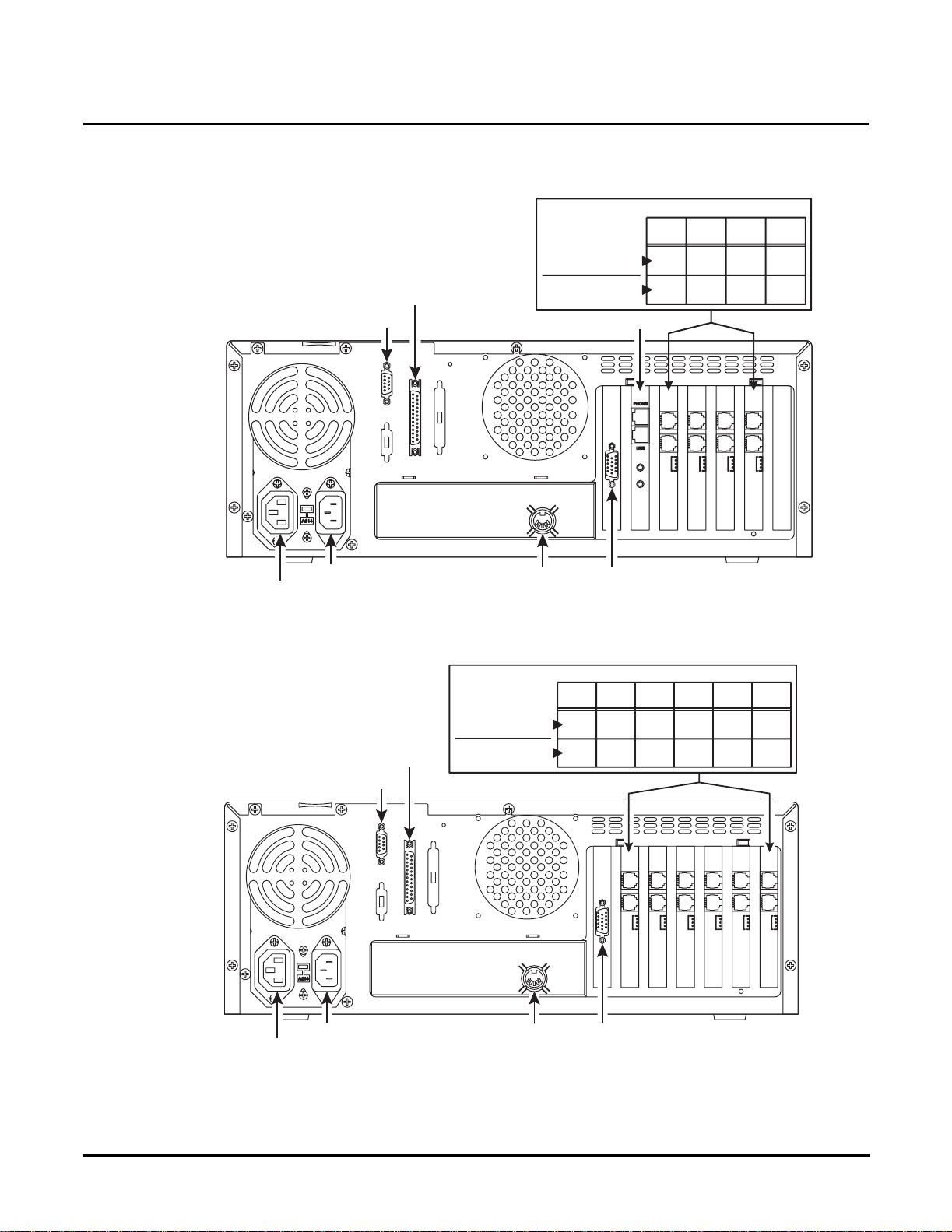
Installing Port Cards
Locally Backing Up the Voice Mail Database
Issue 1-0 ◆2
Locally Backing Up the Voice Mail Database
Locally Backing Up the Voice Mail Database
You should back up the current Voice Mail database as a precaution before you install a Port
Card(s). Backing up the database should be performed locally and not through a modem. During
the procedure, you will have the option to back up messages for individual mailboxes. This is a
lengthy and extensive process. For this reason, it is recommended that you suggest to users that they
delete as many (if not all) of their messages. This will save you time and reduce the number of mes-
sages that you will have to back up.
To locally back up the Voice Mail database:
Note: Instructions assume you are in the Full Screen Editor mode.
1. Insert a floppy disk into the Voice Mail’s floppy disk drive.
2. From the Main Menu,select Install, and press Enter.
3. If requested, type the system password (default is CTL), and press Enter.
4. Select View Current Settings, and press Enter.
5. Write down the phone system that is installed with the Voice Mail as well as the following set-
tings:
Number of Voice Mail Ports
Voice Compression Rate
Mailbox Default Security Code
Default Bilingual Mode
Mailbox Range
Extension Range
6. Return to the Main Menu, select Maintenance, and press Enter.
7. If the system requests it, type the system password (default is CTL), and press Enter.
8. Select Local Backup and press Enter.
The system prompts you through the backup procedure:
Select the files to be processed:
-System Database D
-Mailbox Messages M
File Type (enter Q to Quit)? [D]
9. Default is D(which is the selection you need). Press Enter.
The system provides you with information about the Backup Utility.
10. When you see the prompt, Do you wish to continue,? [Y/N], enter Y. The Voice Mail System
will shut down and exit to the SYSTEM SAVE FILE CREATION utility in DOS.
11. When you see the prompt, Do you wish to save the history data at this time? [Y/N], enter N.
12. The system displays prompts as the Backup Utility progresses. When you see the prompt,
Press any key to continue..., press any key.
13. The system displays status prompts as the data files are copied onto the floppy disk. When
complete, you will see a list of files on your disk as well as a list of files to compare them
against. These are the files that should be copied onto your disk.
Note: If all files were not copied, complete this procedure through step 13 to reboot the Voice Mail.
Repeat steps 5 through 13 to try to back up the files again.
14. Remove the disk from the disk drive.
15. When you see the prompt, Press any key to continue...(and after you removed the disk from
the disk drive), press any key. The Voice Mail will reboot.