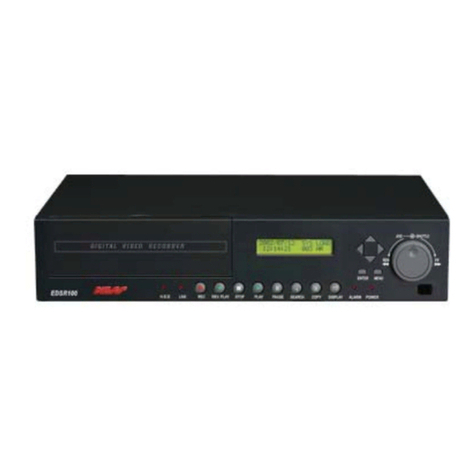
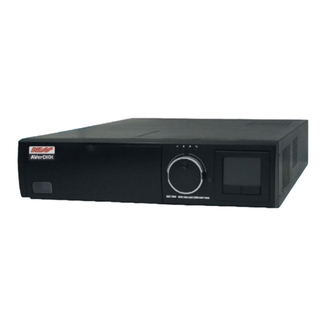
Ness Pro series User manual


2
About this Manual
This manual is designed to assist customers in using their new PRO 16/8 RAID Digital Video Recorder.
Information in this document has been carefully checked for accuracy; however, no guarantee is given as to
the correctness of the contents. The information contained in this document is subject to change without
notice.
Edition
First Edition, March 11, 2008 by NESS SECURITY PRODUCTS PTY LTD
Copyright
This publication contains information that is protected by copyright. No part of it may be reproduced,
transmitted, transcribed, stored in a retrieval system, or translated into any language without permission
from the copyright holders.
Copyright ©2002
All rights reserved
Regulations
♦ CE
♦ C-Tick

3
Warning
It is essential that only the supplied power cord be used.
You are cautioned that changes or modifications not expressly approved by the party responsible for
compliance could void your authority to operate the equipment.
Maintenance
Follow these steps and you will increase the working lifetime of your PRO 16/8 RAID DVR. You will also
reduce the chance of damage to your Digital Video Recorder and personal injury to yourself.
1. Make sure the Digital Video Recorder is turned off before unplugging it.
2. When possible, use a high-quality electrical surge power board or outlet to protect your Digital
Video Recorder. It is also a good idea to unplug your Digital Video Recorder when it is not in
use.
3. Do not use the Digital Video Recorder in a dusty or dirty work area. Dust can cause
contamination of the unit, which can result in malfunction or damage.
4. Clean your Digital Video Recorder exterior casing occasionally with a soft cloth. If you use a
cleanser, make sure that it is only mild detergent. Never use solvents like thinner or benzene,
or abrasive cleansers because these may damage the cabinet. Make sure that the Digital
Video Recorder's power is off when you clean it.
5. Remember to clean your display at regular intervals. Spray window cleanser onto a soft cloth
and then wipe the display. Do not spray the cleanser directly onto the display.
Safety Instructions
Digital Video Recorder
1. Follow all warnings and instructions marked on the Digital Video Recorder.
2. Do not operate your Digital Video Recorder near a source of heat or in direct sunlight.
3. Do not use the Digital Video Recorder in a potentially flammable work area.
4. Do not use your Digital Video Recorder on an unstable working surface. This will prevent your
Digital Video Recorder from falling or being knocked over and damaged.
5. Do not store objects on the top of your Digital Video Recorder. Do not exert pressure on the
Digital Video Recorder.
6. Do not use the Digital Video Recorder near water or other liquids, or in rainy/moist situations.
If liquid enters into your Digital Video Recorder, turn it off and return it to your dealer for
inspection.
7. Do not place the Digital Video Recorder on an unstable cart, stand, or table: The Digital Video
Recorder may fall, causing serious damage to the Digital Video Recorder.
8. Never push objects of any kind into the slots of the Digital Video Recorder cabinet as this may
cause serious damage. The risk of dangerous high voltage contact with internal parts could
result in electrical shock or fire.
9. Unplug the DVR from the power outlet before any major cleaning. Do not spray liquid cleaners
or aerosol cleaners directly onto the DVR. Use a damp cloth for cleaning.
10. Do not attempt to service the Digital Video Recorder yourself. Unplug this product from mains
power and refer all servicing to an authorized dealer.
11. An authorized dealer with manufacturer-approved components must perform replacement of
any component. Unauthorized substitutions may cause a safety hazards and void the warranty.
Power
1. This electronic device must be connected to an approved regulated power outlet, voltage as
indicated on the power input must be observed before connection.
2. This Digital Video Recorder is shipped with its own AC adapter. Do not use the Digital Video
Recorder with a different adapter.

4
3. Do not allow anything to rest on the power cord. Do not place the Digital Video Recorder
where people will walk on the cord.
4. When you disconnect cords, remember to pull them by the plugs and not by the cords
themselves. This will prevent damage to the cords, plugs, ports, and jacks.
5. If an extension cord is used with this Digital Video Recorder, make sure that the total ampere
ratings of the products plugged into the extension cord do not exceed the extension cord’s
ampere rating. Also, make sure that the total current of all products plugged into the wall outlet
does not exceed 15 amperes.

5
Table of Contents
OPERATION FLOW :.................................................................................................................................................... 7
A. INSTALL HARD DISK ................................................................................................................................................ 7
B. RAID CONFIGURATION ..................................................................................................................................... 9
CHAPTER 1.................................................................................................................................................................. 15
DIGITAL VIDEO RECORDER INTRODUCTION................................................................................................................. 15
CHAPTER 2.................................................................................................................................................................. 21
GETTING STARTED...................................................................................................................................................... 21
CHAPTER 3.................................................................................................................................................................. 28
QUICK GUIDE TO ICONS ON THE MAIN SCREEN............................................................................................................ 28
CHAPTER 4.................................................................................................................................................................. 34
CONFIGURING THE CAMERAS ...................................................................................................................................... 34
CHAPTER 5.................................................................................................................................................................. 39
SCHEDULE RECORDING ............................................................................................................................................... 39
CHAPTER 6.................................................................................................................................................................. 48
ACCOUNT SETTINGS.................................................................................................................................................... 48
CHAPTER 7.................................................................................................................................................................. 52
SYSTEM SETTINGS ...................................................................................................................................................... 52
CHAPTER 8.................................................................................................................................................................. 62
ALARM SETTINGS ....................................................................................................................................................... 62
CHAPTER 9.................................................................................................................................................................. 72
ALARM LOG & SCREEN NOTIFICATION ....................................................................................................................... 72
CHAPTER 10................................................................................................................................................................ 74
USER LOG................................................................................................................................................................... 74
CHAPTER 11................................................................................................................................................................ 76
CONFIGURING GENERAL PURPOSE INPUTS - OUTPUTS ................................................................................................. 76
CHAPTER 12................................................................................................................................................................ 78
PAN TILT ZOOM.......................................................................................................................................................... 78
CHAPTER 13................................................................................................................................................................ 84
PLAYBACK.................................................................................................................................................................. 84
CHAPTER 14................................................................................................................................................................ 97
PRINTING.................................................................................................................................................................... 97
CHAPTER 15.............................................................................................................................................................. 102
REMOTE SURVEILLANCE ........................................................................................................................................... 102
APPENDIX A.............................................................................................................................................................. 127
PRO 16/8 RAID SOFTWARE PROBE FUNCTION .......................................................................................................... 127
APPENDIX B.............................................................................................................................................................. 134
TROUBLESHOOTING .................................................................................................................................................. 134

6
APPENDIX C.............................................................................................................................................................. 139
CONFIGURING ACTIVEX............................................................................................................................................ 139
APPENDIX D.............................................................................................................................................................. 141

7
Operation Flow :
Before initial DVR operation, you have to connect all necessary peripherals and
accessories to the DVR system. (please refer to Chapter 1 for the DVR system
introduction)
A. INSTALL HARD DISK
1 . Pull out HDD Mobile Rack from PRO 16/8 RAID DVR System front
panel
2. Install the Hard Disk (SATA HDD) to the Mobile Rack and locked it by
screws of 6#32 L4mm

8
3. After complete step 2, then put HDD back to PRO 16/8 RAID DVR
System
4.Power on PRO 16/8 RAID DVR System
Press power button at the front panel to power on the DVR system.
Note:
The remain HDD capacity on DVR main screen appears “ 0
GB “ due to the DVR Raid Storage has not yet been made
Raid Configuration.

9
B. RAID CONFIGURATION
The Disk Array Configuration Utility allows you to create disk arrays by combining
disks, deleting disks or breaking disk arrays back into their member disks. You
can also specify an available drive as a hot spare. If an array becomes degraded,
the hot
spare will automatically be substituted for the faulted drive.
Invoking the BIOS tool
Power up or reboot your system. Before the boot phase, wait until you see a
screen similar to Figure A.
Figure A. BIOS Tool
Press Alt-3 immediately to bring up the Disk Array Configuration display.
Exiting the BIOS tool
To save your configuration modifications hit the F8 key. After you have hit the F8
key to commit your changes, a list of affected drives will be displayed and you will
be asked to confirm your configuration.
The booting process will resume. To exit the Disk Array Configuration Utility
without saving your changes hit Esc.

10
Disk Array Configuration
• All supported RAID levels (0,1,5,10) can be created based on the number of
drives that the ATA RAID Controller supports.
• Multiple arrays of supported RAID levels can be implemented on a single
controller based on the number of drives that the ATA RAID Controller supports.
The Disk Array Configuration main display shows the current disk drive
configuration.
• Available Drives reports independent drives (JBOD) not associated with an
array and hot spares.
• Disk Arrays lists any existing arrays along with their member disks.
Figure B. Disk Array Configuration Main Display, RAID 1 Example
Throughout the utility (see Figure B) use the Up and Down arrow keys to
navigate, Enter to select the disks or buttons and F1 for context sensitive help.
Toggle Hot Spare verbiage is black when the cursor is over a drive that can be
specified as a hot spare and gray when hot spare cannot be specified. If you’ve
made mistakes and want to start over, pressing F6 will return your starting values.
Pressing Escape will exit the configuration utility as well as abandon your
changes. Pressing F8 will save your changes and exit the utility.

11
Creating a disk array
To create an array, first select the drives to be included by navigating the cursor
over each drive and pressing Enter (see Figure C). An asterisk in the left most
column indicates the drive is selected. You may include from two to eight drives
in the array by selecting drives from the Available Drives section. To include
drives that are part of an existing disk array you must first delete the array.
Figure C. Selecting Drives for a Mirrored Array
Navigate to the Create Array button after selecting all the drives for the array. Hit
Enter to bring up the Create Disk Array display (see Figure D and Figure E for
examples). Check that the proper drives are listed.

12
Figure D. Create Disk Array Display, RAID 0 Example
Figure E. Create Disk Array Display, RAID 5 Example
Select RAID configuration
The PRO 16/8 RAID DVR gives you a choice of four RAID configurations. Select
one.
• Stripe (RAID 0): maximizes performance and capacity through a process
called striping. High performance arrays write portions of a single file across
multiple drives. There is no fault tolerance.
• Mirror (RAID 1): duplicates or “mirrors” the data on both drives. No data will be
lost if one of the drives fails.
• RAID 10 (0+1): combines mirroring and striping, providing both fault tolerance
and high performance. RAID 10 arrays require a minimum of four drives.
Configurations consist of 4, 6 or 8 drives.
• RAID 5: combines parity data and striping, providing fault tolerance, high
capacity and high storage efficiency. The parity data is distributed across all
drives, rather than being concentrated on a single disk. RAID 5 arrays require
a minimum of three drives. Configurations consist of at least 3 drives and up
to 8 drives.

13
Figure F. BIOS Initialization Screen for RAID 5
Select striping size
For a RAID 0 or RAID 10 configuration select the striping size. Sizes of 64K,
128K, 256K, 512K or 1M are selected using the Stripe Size box shown in Figure
D. RAID 5 only allows a 64K stripe size. RAID 1 does not allow the user to select
the striping size.
Select write cache properties
The PRO 16/8 RAID DVR gives you a choice of disabling the write cache for your
disk arrays. Write cache is used to store data locally on the drive before it is
written to the disk, allowing the system to continue with its next task. Enabling the
write cache results in the most efficient access times for your system. There may
be instances when you always want the system to wait for the drive to write all
the data to disk before going on to its next task. For this case, you must disable
the write cache. To disable the write cache, select disable from the array’s Write
Cache State selection. The default for Write Cache State is enable.
Confirm array configuration
Select the OK button to confirm creating the array or Cancel to reject it. The
array is not actually created and no data will be overwritten until you have
finished making all your changes and select the F8 key. The current limitation is
2TB for any physical or logical unit. If you attempt to create an array over 2TB the
BIOS will display the following message:
“The amount of disk space available exceeds the maximum allowable capacity.
The array capacity will be limited to 2 TB.”
For RAID 5 Arrays
Because of the Read-Modify-Write operations, zeros are first written to all drives
in the array before the array is functional. The screen shown in Figure F appears
after selecting OK to confirm array creation. If desired, the write-zeros operation
can be aborted by rebooting the system. Once booted to the operating system,

14
the array goes into initialization mode after a delay of up to ten minutes. The
advantage of doing this is that the RAID 5 can be used immediately, although it
will not be fault tolerant until the initialization is complete. The disadvantage of
doing this is that it will take longer for the array to be fully redundant, as it takes
longer to initialize an array than it takes to write zeros to the array.
For RAID 1 or 10 Arrays
RAID 1 and 10 arrays are not profiled when created, or initialized after booting
into the OS. When the firmware receives the first verify request, given that the
array was never initialized, the initialization will then begin. Any subsequent verify
operations will then perform the verification of the array (check data consistency).
An AEN will inform the user that the first verify is actually an initialization.
Specifying a Hot Spare
The PRO 16/8 RAID DVR gives you the option to specify a hot spare from one of
your Available Drives. If a hot spare is specified and the array degrades, an
event notification will be generated. The hot spare will dynamically replace the
failed drive in an array without user intervention. Select a hot spare by navigating
to an Available Drive. The Toggle Hot Spare verbiage at the bottom of the
screen will be black if the drive can be used as a hot spare. Enter s to select the
hot spare or to disable the hot spare if it is already enabled.

15
Chapter 1
DIGITAL VIDEO RECORDER INTRODUCTION
Your new PRO 16/8 RAID Digital Video Recorder is featuring the high technology
of infrastructure with integration of surveillance system and RAID (A Redundant
Array of Independent Disks) function, provide high performance of advanced
DVR architectures as well as admirable internal storage capacity .
Your PRO 16/8 RAID Digital Video Recorder has built-in software compression
technology for streaming video. An Image Sensor camera can deliver clear, crisp
images at 30 fps (NTSC--National Television Standards Committee--US
Television Standard) (25fps for PAL--Phase Alternating Line--European
Television Standard) — real continuous motion requires 24 fps (frames per
second). And at a resolution of 320x240 (for NTSC) and 720x568 (for PAL) in
True Color allows for comfortable uncluttered viewing.
The most powerful advantage is its built-in RAID feature (RAID 0, 1, 5, 0+1) with
redundant function to pretend data loss from HDD failure. In addition, PRO 16/8
RAID’s amazing massive storage capacity with support 15 hot-swappable HDDs
to offer more than 6 months of recording duration. The high-end redundant
power supplies and fans protect the system from power failure and overheating.
The hot-swappable HDD, power supplies, air blowers and fans keep the system
clutter-free and allow administrators to install and remove the components
quickly and easily. With the high-tech superior architectures, PRO 16/8 RAID not
only lowers the total cost of the surveillance management, but also secure the
data to get rid of the headache of data lost problem.

16
Unpacking the PRO 16/8 RAID DVR
The PRO 16/8 RAID DVR comes securely packaged in a sturdy cardboard
shipping carton. Upon receiving your DVR, open the carton and carefully remove
the contents. If anything is missing or damaged, please contact your dealer
immediately. The shipping carton should contain the following it:
• The PRO 16/8 RAID Digital Video Recorder
• A Mouse
• A Keyboard
• A Power Cord x 1
• The User’s Guide
Do not throw the packaging materials away. You may need them later to
transport or ship the computer for repairs.
Opening the PRO 16/8 RAID DVR
At the front of the Digital Video Recorder, you will find the door covers the hard
disk drive cage and connectors respectively.
Optional Devices
To further enhance the utility of your Digital Video Recorder, there are several
optional products available:
• Removable HDD Tray
• An Alarm Module (only available from the Digital Video Recorder Manufacturer)
• Exchangeable IDE Hard Disk Drive

17
Identifying External Components
Please refer to the text and diagrams below to identify all external components and
accessories of the PRO 16/8 RAID Digital Video Recorder.
Front View
Figure 1-1: Front View of the PRO 16/8 RAID DVR
1. Front Doors
The system is completely enclosed. Opening the doors, by unscrewing the thumb
screws, will reveal 10 hard disk drive bays.
Front Inside View
Please refer to Figure 1-2 and the descriptions that follow to identify the
components on the front side of the digital video recorder.
Figure 1-2: Front Inside View of the PRO 16/8 RAID DVR
1. Removable HDD Tray
The fifteen metal HDD trays enable a secure fit for the HDD and the air ventilation
holes in front ensure that air flows to the HDD thereby cooling off the system.
2. System LED Indicators
1.
2. 3.
4.
5.
6. 7.
8.
Un-screw to
open the door
Un-screw to
open the door
(Power, Fan, Thermal)

18
-Power LED: The Green LED light indicates that system power on
-Fan and Thermal:
The Green LED light indicates that the system fan and thermal are in normal
status.
The Red LED light indicates that the system fan and thermal are failed,
3. Reset Button of system alarm
Once the system fan is failed and system temperature is over high, the system
buzzer will be alarmed, Press this button to re-set the system alarm
4. HDD LED indicators
Left Green LED indicates HDD Power on
Right LED : The origin LED light indicates the HDD is being access
The red LED light indicates the HDD Fail
5. Power button
Press the button to turn on or off the Digital Video Recorder
6. USB port
This is used to connect USB storage devices for the use of data export
7. Card Reader
To connect the storage devices including Compact Flash, Smart Media, Memory
Stick, Secure Digital, Multi Media, IBM Micro Drive and PCMCIA-ATA card for
back-up purpose
8. CD-RW
For back-up purpose
Rear View
Please refer to Figure 1-3 and the descriptions that follow to identify the
components on the rear side of the Digital Video Recorder.
Note !
When the Red LED is keeping blinking, please call help from
your distributor

19
Figure 1-3: Rear View of Digital Video Recorder
1. System Ventilation Fan
This fan generates ventilation for the entire system
2. BNC Camera Input
Use these four BNC camera inputs cards to connect 16 NTSC or PAL compatible
cameras.
3. VGA Display Port
This port is used to connect an external monitor (CRT) or TFT.
4. S-Video Port
This port is used to connect an external CCTV Monitor or TV
5. Ethernet LAN Port
Use an RJ-45 LAN cable to connect to a LAN or Internet.
6. Printer Port
This port is used to connect a printer to the DVR
7. PS/2 Keyboard Port
This port connects a PS/2 compatible keyboard.
8. PS/2 Mouse Port
This port connects a PS/2 compatible mouse.
9. COM 1 Port
This port used for modem or speed dome
10. Power Supply and FAN
Support auto Voltage Switch of 110/220V
11. Power Cord Socket
This socket is used to connect the power cord to the wall power outlet
12. COM 2 Port
This port used for modem or speed dome
13. DI/DO
4in, 4out relay for multiple Dry contact closure alarm input and multiple
relay output for external device connections
---------------------------------------------------------------------------------------------------
1
2
3
4
5
678
9
10
11
12
13

20
Preparing the Digital Video Recorder for Operation
To prepare your Digital Video Recorder for operation, you should first
connect all peripheral devices. Make sure the digital video recorder is turned
off before you do this.
Make sure the floppy drive does not contain a diskette; if it does, press the
eject button to eject an inserted disk.
This manual suits for next models
1
Table of contents
Other Ness DVR manuals
Ness
Ness Pro 4/1 User manual

Ness
Ness Ultimate Premium H.264 User manual

Ness
Ness Premium H.264 DVR User guide
Ness
Ness EDR1600 User manual

Ness
Ness 104-440 User manual
Ness
Ness H.264 HD-SDI User manual
Ness
Ness 8-channel models User manual
Ness
Ness IQ-MDVR-4 User manual

Ness
Ness EDSR400M User manual

Ness
Ness HD-960H User manual

Ness
Ness IQ-MDVR User manual
Ness
Ness PowerPlex EDR400 User manual
Ness
Ness EDR1640 User manual
Ness
Ness 104-424 Nano Use and care manual
Ness
Ness IQ-MDVR-8 User manual

Ness
Ness 104-460 Auto-IP NVS User manual
Ness
Ness IQ-SDI-4 User manual
Ness
Ness Ultimate Series User manual
Ness
Ness IQ User manual

Ness
Ness IQ-MDVR-4 User manual

