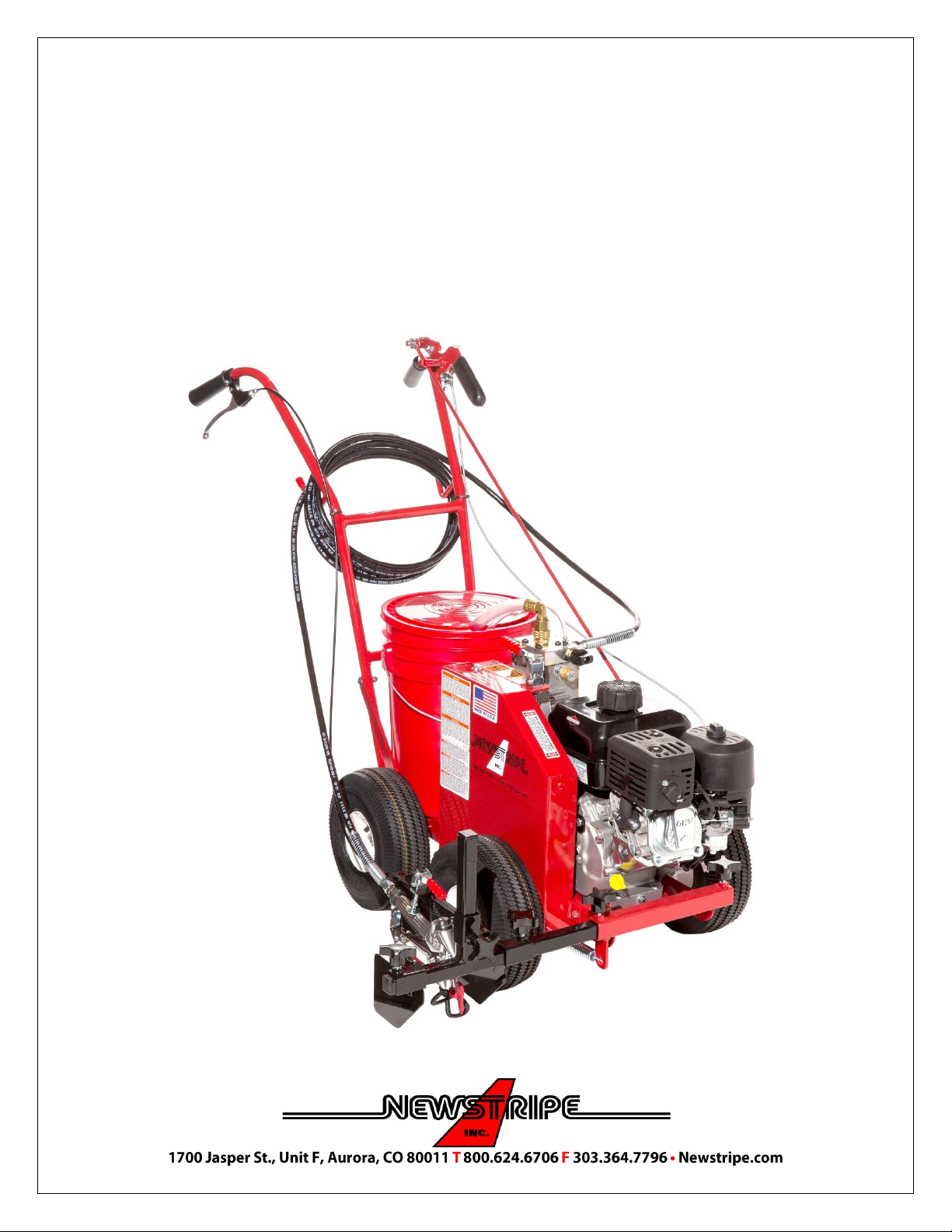
4600™ Self-Propelled Airless Sprayer
ALWAYS wear safety goggles or protective eye-wear when operating the unit!
4600™ SP Manual / 3031.0623
Page 4 of 10
SPRAY TIP CLEANING DURING USE
1. Place the Spray Control Knob in the re-circulating
position, and then squeeze the spray trigger lever to
release the pressure from the system.
5. Turn the Prime/Spray knob to the spray position and
resume spraying. If the spray gun continues to clog,
check the filter in the gun handle.
2. Turn the spray tip arrow on the spray gun so that the
arrow points toward the gun.
6. Turn the Prime/Spray knob to the prime position. Turn
off the machine. Remove the paint hose from the
spray gun.
3. Turn the spray control knob to the spray position and
trigger the gun. This should clear the gun. Turn the
spray control knob to the prime position and trigger
the gun to release the pressure.
7. Press the trigger lock on the side of the spray gun to
lock the spray trigger. Remove the gun from the gun
mount. Push forward on the spray trigger guard to
release the guard from the front of the gun.
4. Reverse the spray tip so that the spray tip arrow points
toward the ground.
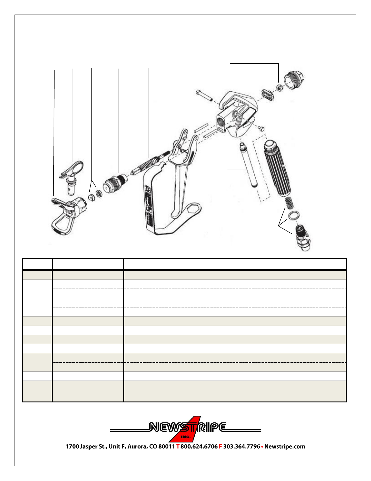
8. You can now unscrew the handle. The filter pulls
straight out of the handle. Only rinse the filter to clean
it. If the filter is still clogged, collapsed or dented,
replace the filter. Reinstall the filter. If there are still
issues, proceed to the cleaning procedure.
CLEANING PROCEDURE
1. Remove the pail with paint.
2. Place an empty pail on the machine and fill it with 2 gallons of water if using latex paints. If using an
alkyd or oil base paint, use enough of the appropriate solvent, that suction filter is covered.
3. Place the return hose in a waste container.
4. Make sure the Spray Control Knob is in the Prime/Re-circulating Position.
5. Start the engine and let it run in the prime position until the fluid in the return hose runs clear.
6. Turn the Spray Control Knob to the Spray Position.
7. Trigger the gun until the gun spray runs clear.
8. Turn the spray control knob to the prime position, turn off the engine, and then trigger the spray gun
to release the system pressure.
9. Wipe down the suction tube and return hose.
10. Clean the spray tip if needed with a nylon bristle brush. DO NOT USE METAL BRUSHES
PRECAUTIONARY WARNING
ALWAYS release the pressure in the system before changing or cleaning
the spray tip. (Place the Spray Control Knob in the re-circulating position,
turn off the sprayer and squeeze the spray trigger to release the pressure)
NEVER use fuels to clean the equipment
DO NOT use solvents containing halogenated hydrocarbons such as methyl
bromine, carbon tetrachloride and ethyl iodine
DO NOT attempt to clean a clogged gun filter. You must replace it.
DO NOT use brushes with metal bristles or any metal object to clean the
spray tip of dried paint. Replace the tip if it cannot be cleaned!