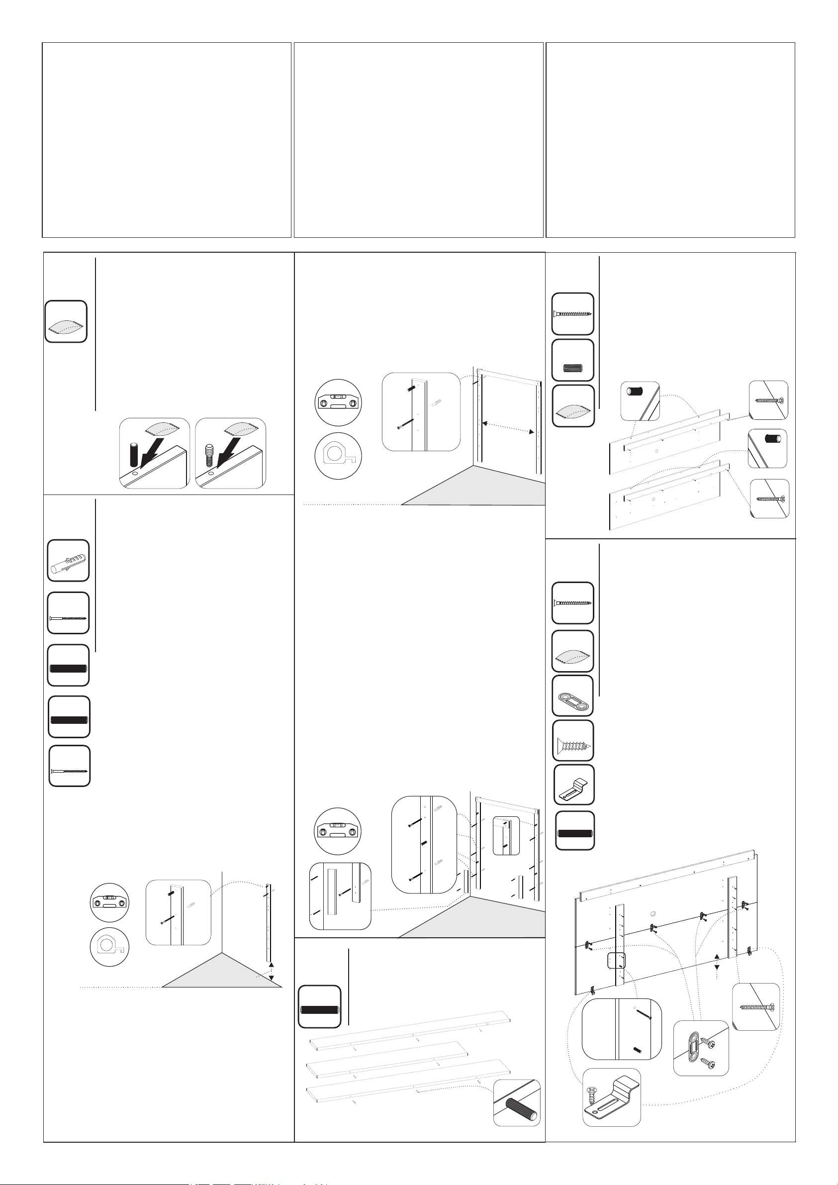
manuals.online logo
Brands
  1. Home
  2. •
  3. Brands
  4. •
  5. Notável Móveis
  6. •
  7. Indoor Furnishing
  8. •
  9. Notável Móveis PAINEL NT 1010 User manual

Notável Móveis PAINEL NT 1010 User manual

Instalação
Instalación
Installation
ESQUEMA DE MONTAGEM
INSTRUCCIONES DE MONTAJE
ASSEMBLY INSTRUCTIONS
RELAÇÃO DE FERRAGENS | LISTA DE HARDWARE | LIST OF HARDWARE
01. A marcação com o código do produto e o número das peças nas fitas aparentes pode ser removida
com pano e álcool.
01. La marcación con el código del producto y el número en las cintas aparentes pueden ser quitados con
paño y alcohol.
01. Marking with product code and number of parts on the apparent ribbons can be removed with cloth and
alcohol.
02. Para reclamações, ter à mão a etiqueta do produto com número do lote e data da fabricação.
02. Para cualquiera que sea la reclamación hay que tener siempre a mano la etiqueta del producto con el
número del lote y la fecha de fabricación.
02. For complaints always have the product label with the batch number and manufacturing date at hand.
03. Sr. Montador, favor conferir as peças antes da montagem, pois só efetuamos a troca do produto antes de
ser montado.
03. Señor ensamblador, favor conferir las piezas antes del montaje, pues sólo cambiamos los productos antes
de ensamblados.
03. Mr. Assembler, please check parts before assembling. We only replace products before put together.
COD: NT1010
PAINEL NT 1010
PANEL NT 1010
PAINEL NT 1010
DIMENSÕES TOTAIS | DIMENSIONES TOTALES |
: 1832x1815x310mm OVERALL DIMENSIONS
VOLUME | VOLUMEN | VOLUME: 02
CAPACIDADE TV | CAPACIDAD TV | TV SIZE: 60''
DESTORNILLADOR
ELETRIC SCREW
DRIVER
MARTILLO
HAMMER
DESTORNILLADOR
Y DE CRUCETA
PHILLIPS
SCREWDRIVER
CINTA MÉTRICA
MEASURING
TAPE
NIVEL
NIVEL
5M
FERRAMENTAS PARA MONTAGEM E INSTALAÇÃO
HERRAMIENTAS PARA ENSAMBLAJE E INSTALACIÓN
TOOLS FOR ASSEMBLY AND INSTALLATION
Ferramentas não fornecidas | Herramientas no proporcionadas | Tools not supplied
Montagem
Ensamblaje
Assembly
ATENÇÃO: Sugerimos montar os produtos sobre
a embalagem para evitar arranhões nas peças.
PRECAUCIÓN: Sugerimos ensamblar los
productos sobre el embalaje para evitar
rayaduras en las partes.
ATTENTION: We suggest assembling the
products on the packaging to avoid scratches on
the parts.
•A TV deverá ser fixada no Painel. Não
utilize a TV apenas apoiada sobre nicho.
•La TELE deberá ser fijada en el panel. No
utilice la TELE apoyada sólo sobre el nicho.
•The TV should be attached to the Panel. Do
not use the niche-only TV.
PÁGINA | PAGINA | PAGE: 01
PARAFUSADEIRA NÍVEL CHAVE PHILIPS
E FENDA MARTELO TRENA
13
13
5kg
5kg
5kg
0,5kg
0,5kg
CÓD PRODUTO
CÓD PRODUCTO
CODE
Nº PEÇA
NR. PIEZA
ITEM
DESCRIÇÃO
DESCRIPCIÓN
DESCRIPTION
MATERIAL
COD PEÇA
COD PIEZA
PART CODE
QTDE
CTD.
QTY.
COMP.
LARGO
LENGTH
LARG
ANCHO
WIDTH
ESP
ESP
THICK
NT1010 1 BASE INFERIOR | BASE INFERIOR | LOWER BASE MDP 43128-01 1 1730 255 25
NT1010 2 TAMPO INFERIOR | CUBIERTA INFERIOR | LOWER TOP MDP 43129-02 1 1350 255 25
NT1010 3 TAMPO SUPERIOR | CUBIERTA SUPERIOR | UPPER TOP MDP 43130-03 1 1730 177 25
NT1010 4 PAINEL INFERIOR | PANEL INFERIOR | LOWER PANNEL MDP 43131-04 1 1815 525 15
NT1010 5 PAINEL CENTRAL INFERIOR | PANEL CENTRAL INFERIOR | CENTRAL LOWER PANEL MDP 43132-05 1 1815 445 15
NT1010 6 PAINEL CENTRAL SUPERIOR | PANEL CENTRAL SUPERIOR | CENTRAL UPPER PANEL MDP 43140-06 1 1815 445 15
NT1010 7 PAINEL SUPERIOR | PANEL SUPERIOR | UPPER PANEL MDP 43133-07 1 1815 365 15
NT1010 8 SUPORTE TRASEIRO | SOPORTE TRASERO | REAR SUPPORT MDP 43134-08 2 1730 80 15
NT1010 9 SUPORTE TRASEIRO | SOPORTE TRASERO | REAR SUPPORT MDP 43135-09 2 750 80 15
NT1010 10 SUPORTE PAREDE | PARED SOPORTE | WALL SUPPORT MDP 43136-10 2 1730 80 15
NT1010 11 SUPORTE SUPERIOR | SOPORTE SUPERIOR | UPPER SUPPORT MDP 43137-11 1 1210 80 15
NT1010 12 KIT ACESSÓRIO | KIT ACCESORIOS | ACCESSORIES SET . 43138-12 1 . .
NT1010 13 SUPORTE APOIO | SOPORTE APOYO | SUPPORT BACKING MDP 43222-13 2 476 80 15
RELAÇÃO DE PEÇAS | LISTA DE PIEZAS | PARTS LIST
SUPORTE VIDRO
SOPORTE DE VIDRIO
GLASS SUPPORT
G
PARAFUSO 4,5x30mm CABEÇA CHATA
TORNILLO 4,5x30mm CABEZA PLANA
4,5x30mm FLAT HEAD SCREW
PW
4
8
A
CAVILHA MADEIRA 6x30mm
CLAVIJA MADERA 6x30mm
6X30MM WOODEN DOWEL
2
AN
CAVILHA MADEIRA 6x50mm
CLAVIJA MADERA 6x50mm
6X50MM WOODEN DOWEL
18
PARAFUSO 3,5X25MM CABEÇA CHATA
TORNILLO 3,5X25MM CABEZA PLANA
3.5X25MM FLAT HEAD SCREW
W
10
AC
CAVILHA MADEIRA 8x20mm
CLAVIJA MADERA 8x20mm
8X20 WOODEN DOWEL
4
KIT TAPA FURO CROMADO 10mm
KIT TAPA AGUJERO CROMO 10mm
ADHESIVE HOLE COVER CHROME SET 10mm
CR
8
PARAFUSO 5x50mm CABEÇA CHATA
TORNILLO 5x50mm CABEZA PLANA
5x50mm FLAT HEAD SCREW
PB
8
PARAFUSO 5X70mm CABEÇA CHATA
5X70mm FLAT HEAD SCREW
5x70mm FLAT HEAD SCREW
PM
1
LED
KIT LED
KIT LED
LED KIT
8
BUCHA PLÁSTICA 8mm
TACO PLASTICO 8mm
8mm PLASTIC BUSHING
BPBP
PD
PARAFUSO 4,5X60mm CABEÇA CHATA
TORNILLO 4,5X60mm CABEZA PLANA
4,5x60mm FLAT HEAD SCREW 11
12
PP
PARAFUSO 3X12mm CABEÇA CHATA
3X12mm CABEZA PLANA
3X12mm FLAT HEAD SCREW
PP
3
SC
SACHÊ DE COLA 5g
SACHÊ DE PEGAMENTO 5g
5G GLUE SACHET
2
PASSA FIO 46mm
PASA-CABLES 46mm
46mm THREAD GUIDE
PS
4
JUNÇÃO 36mm
JUNCIÓN 36mm
36mm JUNCTION
EE
KIT TRAVA PAINEL + PARAFUSO
KIT BLOQUEO PANEL + TORNILLO
KIT LOCK PANEL + SCREW
KT 1
4
PASSO 2
PASO 2
STEP 2
FIXAÇÃO DAS COLUNAS NA PAREDE
ATENÇÃO: Antes de fixar o armário na parede
verifique se o local possui condições adequadas para
suportar o produto.
1 - Posicione uma das colunas 10 na parede na altura que
deseja fixar o produto. Em seguida pegue uma furadeira e
fure a parede atravessando a broca no primeiro furo da
parte superior da coluna
2 - Retire a coluna e insira a bucha BP (8mm) na parede
3 - Alinhe novamente a coluna na parede e fixe-a no
primeiro furo da parte superior com o parafuso PM
(5x70mm)
4 - Em seguida insira a cavilha AN (6x50mm) no furo
superior conforme desenho abaixo.
FIJACIÓN DE LAS COLUMNAS EN LA PARED
Precaución: antes de fijar el armario en la pared
compruebe si el local tiene condiciones adecuadas
para soportar el producto.
1 - Posicione una de las columnas 10 na parede na altura
que deseja fixar o produto. En la pared en la altura que
quiere fijar el producto. Luego utilice un taladro y perfore la
pared y pase la broca en el primer agujero de la parte
superior de la columna.
2 - Saque la columna e inserte el taco BP (8mm) en la
pared.
3 - Alinee otra vez la columna en la pared y fíjela en el
primer agujero de la parte superior con el tornillo PM
(5x70mm)
4 - Luego, inserte la clavija AN (6x50mm) en el agujero
superior conforme el dibujo abajo.
FIXING THE COLUMNS ON THE WALL
ATTENTION: Before fixing the cabinet on the wall,
check if the location has adequate conditions to
support the product.
1 - Place one of the columns 10 on the wall at the height
you want to fix the product. Then take a drill and drill the
wall through the drill in the first hole at the top of the column
2 - Remove the column and insert the BP bushing (8mm)
into the wall
3 - Align the column on the wall again and fix it to the first
hole on the top with the PM screw (5x70mm)
4 - Then insert the AN pin (6x50mm) into the upper hole as
shown in the drawing below.
PÁGINA | PAGINA | PAGE: 02
TERMO DE GARANTIA
A presente garantia deverá ser exercida nos
prazos aqui indicados, mediante apresentação deste
certificado e da nota fiscal.
Para que o produto esteja assegurado pela
garantia conferida neste documento, o cliente deverá
adotar as seguintes orientações e cuidados quanto à
montagem, conservação e limpeza.
MONTAGEM
A montagem deverá ser feita obedecendo as
instruções do manual de montagem que será
fornecido com o produto no momento da entrega.
Para o uso adequado e conservação do móvel
deve-se evitar maus tratos, como por exemplo: bater
portas e gavetas, arrastar ou riscar o móvel, umidade
ou calor excessivos e exposição ao sol, para evitar
possível alteração na cor original dos móveis.
Não será de responsabilidade da Notável
Móveis problemas que tenham origem na utilização
dos produtos de forma inadequada ou quebra do
móvel em função do excesso de peso por colocação
de pedras de granito, mármore e outros.
- O peso suportado por cada prateleira deverá
obedecer os valores indicados na ilustração.
Também não serão de responsabilidade da
Notável Móveis, problemas que tenham origem em:
- Instalações elétricas ou hidráulicas.
- Ações de cupins ou outras pragas.
- Armazenamento e deslocamento do móvel
em lo c a i s im p r ó p r i os e nã o de d e t i zados
periodicamente.
- Todo e qualquer recorte ou alteração nos
móveis.
- Uso de produtos de limpeza ou abrasivos não
recomendados.
CONSERVAÇÃO E LIMPEZA
Para maior durabilidade, recomenda-se que a
limpeza dos móveis seja feita da seguinte forma:
Nas partes externas (portas, laterais e frente
de gaveta), internas, vidros e espelhos, a limpeza
deverá ser feita com pano limpo e levemente
umedecido em água e sabão neutro. Em seguida,
deverá ser passado um pano limpo e seco.
Em caso de transferência do móvel para local
diverso, esta só poderá ocorrer através de
profissional especializado, sendo que para a
movimentação do móvel é necessário que o mesmo
seja levantado do chão. O produto não deve ser
arrastado, pois avarias no manuseio e transporte,
não estão contempladas na garantia.
PRAZO DE GARANTIA
O prazo de garantia será de noventa (90) dias,
conforme prevista no artigo 26 do Código do
Consumidor, a contar da efetiva entrega do produto,
desde que observadas as condições normais de uso
e conservação. Essa garantia cobre defeitos de
fabricação.
DOCUMENTO DE FIANZA
Esta garantía se ejerce dentro del periodo en el
presente documento, con la presentación de este
certificado y la factura.
Para que el producto esté garantizado por la
garantía dada en este documento, el cliente debe
tomar las siguientes directrices y precauciones de
instalación, mantenimiento y limpieza.
MONTAJE
El montaje se realizará siguiendo las
i n s tr u cc io n es d e en s am bl a je q u e s e r án
proporcionadas con la entrega del producto.
Para el uso adecuado y la conservación del
mueble se debe evitar los malos tratos, tales como:
golpear puertas y cajones, arrastrar o arañar los
muebles, humedad o el calor excesivos y la
exposición al sol para evitar un posible cambio en el
color original de los muebles.
No será responsabilidad de Notável Móveis
problemas que se originen en el uso de los productos
de forma inapropiada o ruptura del mueble en función
de exceso de peso mediante la colocación de piedras
de granito, mármol y otros.
- El peso soportado por cada estante debe
cumplir con los valores indicados en la ilustración.
Tampoco serán responsabilidad de Notável
Muebles los problemas que se originan en:
- Instalaciones eléctricas o hidráulicas.
- Acciones de termitas u otras plagas.
- Almacenamiento y cambio del mueble en
locales inapropiados y no fumigados periódicamente.
- Todo y cada corte o cambio en los muebles.
- Uso de productos de limpieza o abrasivos no
recomendados.
CUIDADO Y LIMPIEZA
Para una mayor durabilidad, se recomienda
que la limpieza de los muebles sea hecha como sigue:
En las partes externas (puertas, laterales y
frontales de cajón), internas, vidrios y espejos, la
limpieza debe ser hecha con paño limpio y
ligeramente humedecido con agua y jabón suave. A
continuación, se debe pasar un paño limpio y seco.
En el caso del traslado del mueble a otro sitio,
esto sólo puede ocurrir a través de profesionales
especializados, y para el manejo del mueble se
requiere que el mismo sea levantado del piso. El
producto no debe ser arrastrado pues daños en la
manipulación y el transporte no están cubiertos por la
garantía.
PERÍODO DE GARANTÍA
El plazo de garantía será de noventa (90) días,
conforme dispuesto en el artículo 26 del Código de
Consumidor, a contar de la fecha de entrega real del
producto, teniendo debidamente en cuenta las
condiciones normales de uso y almacenamiento. Esta
garantía cubre defectos de fabricación.
WARRANTY TERM
This warranty shall be applied within the time
limits specified herein, by presentation of this
certificate and invoice.
In order for the product to be covered by the
warranty provided in this document, the client should
follow the following guidelines and precautions for
assembly, maintenance and cleaning.
ASSEMBLY
Assembly must be carried out according to the
instructions in the assembly manual which is
supplied with the product at the time of delivery.
For proper use and conservation of this
furniture, mistreatment should be avoided, such as
hitting doors and drawers, dragging or scratching the
furniture, excessive moisture or heat to avoid
possible changes in its original color.
Problems from improper use of the products
as breaking of the furniture due to the excess weight
by installation of granite, marble, and others will not
be the responsibility of Notável Móveis
- The weight withstood by each shelf/drawer
must comply with the values indicated in illustration.
It will not be responsibility of the Notável
Móveis either problem from:
- Electrical or hydraulic installations.
- Actions of termites or other pests.
- Storage and moving of the furniture in
inappropriate places and not fumigated periodically.
- Any trimming or alteration in the furniture.
- Use of cleaning agents or abrasives not
recommended.
UPKEEP AND CLEANING
For durability, it is recommended that the
furniture be cleaned this way:
In the outer parts (doors, sides and drawer
front), inside, glass and mirrors, the cleaning should
be done with a cloth clean and lightly moistened with
mild soap and water. Then a clean, dry cloth should
be used.
In case of transfer of the furniture to a different
place, this can only be done by specialized
professionals, and for the moving of the furniture it is
necessary that it is lifted off the ground. It should not
be dragged because malfunctions due to handle and
moving are not covered by the warranty.
WARRANTY TIME
The warranty time shall be ninety (90) days, as
provided in article 26 of the Consumer Code, as of the
effective delivery of the product, provided that normal
conditions of use and conservation are observed.
This warranty covers manufacturing flaws.
SC 1
PASSO 1
PASO 1
STEP 1
Fazer a preparação de todas as peças, com os acessórios e
as quantidades dos mesmos. ATENÇÃO: Antes de fixar as
cavilhas A e as cavilhas escalonadas CC é necessário
passar cola nos furos para ajudar a travar as peças. Evite
excesso de cola, apenas uma pequena quantidade é
suficiente para a fixação.
Hacer la preparación de todas las piezas, con los
accesorios y las cantidades de los mismos. PRECAUCIÓN:
antes de fijar las clavijas A e las clavijas escalonadas CC es
necesario usar pegamento en los agujeros para ayudar a
trabar las piezas. Evite pegamento demasiado pegamento.
Sólo una pequeña cantidad es suficiente para la fijación.
Prepare all parts, accessories and quantities. ATTENTION:
Before fastening the A Dowels and the CC Staggered
Dowels, it is necessary to apply glue into the holes to help
lock the parts. Avoid excess glue; only a small amount is
enough for securing.
AN 2
BP 8
PM 8
AC 4
PW 4
500mm
10
PAREDE
10
10
5M
1050mm
10
1010 11
10
5M
10
10
10
11
13
18
13
13
5 - Pegue a segunda coluna e deixe-a a uma distância de aproximadamente
1050mm da primeira coluna fixada
6 - Utilize a peça 11 encaixada nas 2 colunas no local indicado abaixo para
auxiliar no alinhamento da peça. É necessário também a utilização de um
nível.
7 - Após alinhar a peça repita as operações 1, 2 e 3 para a segunda coluna
8 - Em seguida insira a cavilha AN (6x50mm) no furo superior conforme
desenho abaixo
5 - Tome la segunda columna y déjela a una distancia alrededor de 1050mm
de la primera columna fijada.
6 - Utilice la pieza 11 encajada en las dos columnas en el local indicado
abajo para ayudar en el alineamiento de la pieza. Es necesario el uso de un
nivel.
7 - Luego de alinear la pieza, repite las operaciones 1, 2 y 3 para la
segunda columna.
8 - A continuación, inserte la clavija AN (6x50mm) en el agujero superior
conforme dibujo abajo.
5 - Take the second column and leave it at a distance of approximately
1050mm from the first column fixed
6 - Use the piece 11 fitted in the 2 columns in the location indicated below to
assist in the alignment of the piece. It is also necessary to use a level.
7 - After aligning the piece, repeat operations 1, 2 and 3 for the second
column
8 - Then insert the AN pin (6x50mm) into the top hole as shown in the
drawing below
9 - Utilize a furadeira para furar a
parede nos demais furos das 2
colunas
10 - Retire a peça 11 e desloque as
colunas um pouco para o lado para
inserir as demais buchas BP (8mm)
na parede
11 - Em seguida alinhe novamente
as colunas e insira os parafusos PM
(5 x 70mm), travando as colunas
nas buchas BP (8mm)
12 - Insira as cavilhas AC
(8x20mm) nos furos centrais e
inferiores das 2 colunas conforme
desenho abaixo
13 - Fixar as peças 13 nas peças 10
com parafuso PW 4,5x30,
alinhando a peça 13 na parte
inferior da peça 10.
9 - Utilice un taladro para perforar la
pared en los demás agujeros de las
dos columnas.
10 - Saque la pieza 11 y cambie las
columnas un poco para el lado para
insertar los otros tacos BP (8mm)
en la pared.
11 - A continuación, alinee otra vez
las columnas e inserte los tornillos
PM (5 x 70mm), para trabar las
columnas en los tacos BP (8mm).
12 - Inserte las clavijas AC
(8x20mm) en los agujeros centrales
e inferiores de las 2 columnas
conforme dibujo abajo.
13 - Fijar las piezas 13 en las
piezas 10 con tornillo PW 4,5x30,
alineando la pieza 13 en la parte
inferior de la pieza 10.
9 - Use the drill to drill the wall in the
other holes of the 2 columns
10 - Remove part 11 and move the
columns a little to the side to insert
the other BP bushings (8mm) into
the wall
11 - Then align the columns again
and insert the PM screws (5 x
70mm), locking the columns in the
BP bushings (8mm)
12 - Insert the AC pins (8x20mm)
into the central and lower holes of
the 2 columns as shown in the
drawing below
13 - Fix pieces 13 on pieces 10 with
a 4.5x30 PW screw, aligning piece
13 on the bottom of piece 10.
PASSO 3
PASO 3
STEP 3
1 - Insira as cavilhas A (6x30mm) nas peças 1,2 e 3
1 - Insertar las clavijas A (6x30mm) en las piezas 1, 2 y 3
1 - Insert the A (6x30mm) dowels to the pieces 1, 2 and 3
AC 4
W8
SC 1
A8
3
1
6
8
4
8
6
5
9
9
inferior
lower
25mm
2
W10
SC 1
PP 8
EE 4
KT 2
AC 2
PASSO 4
PASO 4
STEP 4
1 - Insira as cavilhas AC (8x20mm) nas peças 4 e 6
2 - Encaixe a peça 8 na peça 6 e fixe-as com os parafusos
W (3,5x25mm)
1 - Insertar las clavijas AC (8x20mm) en las piezas 4 y 6
2 - Encaje la pieza 8 en la pieza 6 y fije-las con los tornillos
W (3,5x25mm)
1 - Insert the AC (8x20mm) dowels to the parts 4 and 6
2 - Fit the piece 8 on piece 6 and fix them with the W
(3,5x25mm)
PASSO 5
PASO 5
STEP 5
1 - Encaixe a peça 9 na peça 5 e 6 e fixe-as com os
parafusos W (3,5x25mm) deixando 25 mm da parte inferior.
2 - Fixe as peças 5 e 6 utilizando as junções EE com
parafusos X (3x12mm)
3 - No terceiro furo superior das peças 9 não deve-se
colocar parafuso. No terceiro furo inferior das peças 9
encaixe as cavilhas AC (6x20mm).
4 - Alinhe as travas KT no painel 5 nos locais indicados
abaixo e fixe-as com os parafusos do Kit trava painel KT.
1 - Montar la pieza 9 en las piezas 5 y 6 y fijarlas con
tornillos W (3,5x25 mm) dejando 25 mm desde abajo.
2 - Fije las piezas 5 y 6 utilizando las juntas EE con tornillos
X (3x12mm)
3 - No se deben insertar tornillos en el tercer orificio superior
de las piezas 9. Inserte los pernos de CA (6x20 mm) en el
tercer orificio inferior de las piezas 9.
4 - Alinee los pestillos KT del panel 5 en los lugares
indicados a continuación y fíjelos con los tornillos del kit de
bloqueo del panel KT.
1 - Fit part 9 to parts 5 and 6 and fix them with screws W
(3.5x25mm) leaving 25 mm from the bottom.
2 - Fix parts 5 and 6 using the EE joints with X screws
(3x12mm)
3 - Screws must not be inserted in the third upper hole of
parts 9. Insert the AC bolts (6x20mm) into the third bottom
hole of parts 9.
4 - Align the KT latches on panel 5 in the locations indicated
below and secure them with the screws of the KT panel
latch kit.
PÁGINA | PAGINA | PAGE: 03
PASSO 6
PASO 6
STEP 6
1 - Encaixe as peças 1 e 2 na peça 4 e fixe-as com os
parafusos PD (4,5x60mm)
1 - Encaje las piezas 1 y 2 en las piezas 4 y fije-las con
los tornillos PD (4,5x60mm)
1 - Fit the parts 1 and 2 on the pieces 4 and fix them
withPD (4,5x60mm) screws
PD 7
4
1
2
PASSO 7
PASO 7
STEP 7
1 - Passe os conectores da luminária através do furo
indicado com as letras A e B da peça 16
2 - Encaixe a luminária no furo A da peça 16
1 - Pasar los conectores de la luminaria por el orificio
indicado con las letras A y B del pieza 16
2 - Insertar la luminaria en el orificio A de la pieza 16
1 - Pass the luminaire connectors throught the holes
indicated with the letters A and B of piece 16
2 - Insert the luminaire into hole A of part 16
LED 1
A
B
1
2
A
ê
LED 1
12
A
A
ê
AZUL
BLUE
VERMELHO
ROJO
RED
AZUL
BLUE
1
2
3
7
PASSO 8
PASO 8
STEP 8
1 - Passe os conectores do interruptor através do furo A
da peça 7
2 - Encaixe o interruptor no furo A da peça 7
1 - Pase los conectores del interruptor por el orificio A de
la parte 7
2 - Inserte el interruptor en el orificio A de la parte 7
1 - Pass the switch connectors through hole A of part 7
2 - Insert the switch in hole A of part 7
PASSO 9
PASO 9
STEP 9
Antes de fixar o painel superior na parede faça as conexões do
LED:
1 - Conector vermelho da luminária com o conector vermelho
do interruptor
2 - Conector azul do interruptor com o conector azul da tomada
3 - Conector azul da luminária com o conector azul da tomada
Antes de fijar el panel superior en la pared haga las conexiones
del LED:
1. Conector rojo de la lámpara con el conector rojo del
conmutador
2. Conector azul del conmutador con el conector azul del
enchufe.
3. Conector azul de la lámpara con el conector azul del enchufe.
Before fixing the top panel to the wall, make the LED
connections:
1 - Red luminaire connector with red switch connector
2 - Blue switch connector with blue plug connector
3 - Blue connector of the luminaire with the blue connector of
the socket
PB 4
CR 4
PS 2
10
4
VISTA A
VIEW A
A
910
6
5
10
6
5
8
8
5
8
PASSO 12
PASO 12
STEP 12
1 - Para a montagem do segundo painel siga as instruções abaixo:
- Encaixe a peça 5 sobre a peça 8 com os suportes na peça 5
- Encaixe a peças 5 e 6 na peças 10 e fixa-a com parafuso PB (5X50)
2 - Rosqueie a parte maior do tapa furo CR na parte menor para dar
acabamento a montagem
3 - Encaixe o passa fio PS na peça 4 e 6
1 - Para el montaje del segundo panel siga las instrucciones a
continuación:
- Enganche la pieza 5 sobre la pieza 8 con los soportes en la pieza 5
- Enganche las piezas 5 y 6 en las piezas 10 y la fija con tornillo PB
(5x50)
2 - Rosque la parte más grande de la tapa del agujero CR en la parte más
pequeña para acabado de montaje
3 - Enchufe el paso del cable PS en la pieza 4 y 6
1 - To assembly the second panel, follow the instructions bellow:
- Fit the piece 5 over the piece 8 with the supports on the piece 5
- Fit the pieces 5 and 6 on pieces 10 and fix it with PB (5x50mm) screws,
2 - Thread the larger part of the CR hole cover to the smaller part to finish
the assembly
3 - Fit the PS thread-guide to the parts 4 and 6
PASSO 10
PASO 10
STEP 10
1- Fazer o indicada no passo 09 passando os fios da
peça 3 pelos furos A e B
2 - Encaixe as peças 3 na peça 7 e fixe-as com os
parafusos PD (4,5x60mm)
3 - Alinhe as travas KT no painel 7 nos locais indicados
abaixo e fixe-as com os parafusos do Kit trava painel
KT.
1- Hacer lo indicado en el paso 09 pasando las roscas
de la pieza 3 por los agujeros A y B
2 - Coloque las piezas 3 en la pieza 7 y fíjelas con
tornillos PD (4,5x60 mm)
3 - Alinee los pestillos KT del panel 7 en los lugares
indicados a continuación y fíjelos con los tornillos del kit
de bloqueo del panel KT.
1- Do the indicated in step 09 passing the threads of
part 3 through holes A and B
2 - Fit parts 3 to part 7 and fix them with PD screws
(4.5x60mm)
3 - Align the KT latches on panel 7 in the locations
indicated below and secure them with the screws of the
KT panel lock kit.
PD 4
PB 2
CR 2
7
3A
B
10
10
4
KT 2
PASSO 11
PASO 11
STEP 11
1 - Encaixar a montagem do painel 4 nas colunas 10
2 - Encaixar o parafuso PB (5x50mm) dentro da parte
menor do tapa furo cromado e em seguida adicionar as
peças 4 a 10.
3 - Rosqueie a parte maior do tapa furo CR na parte
menor para dar acabamento a montagem
1 - Encajar el conjunto del panel 4 en las columnas 10
2 - Inserte el tornillo PB (5x50 mm) en la parte más
pequeña de la tapa del orificio cromado y luego agregue
las partes 4 a 10.
3 - Atornille la parte más grande de la tapa del agujero
CR a la parte más pequeña para terminar el montaje
1 - Fit panel 4 assembly to columns 10
2 - Insert the PB screw (5x50mm) into the smallest part
of the chrome hole cover and then add parts 4 to 10.
3 - Screw the larger part of the CR hole cover to the
smaller part to finish the assembly
PASSO 13
PASO 13
STEP 13
1 - Para a montagem do terceiro painel adicione a peça 11
as peças 10 com cavilha A N(6x50); Encaixe o conjunto
montado no passo 10, colocando a peça 7 na peça 11 com
cavilha AN (6x50 mm)
2 - Encaixe o parafuso PB (5x50mm) dentro da parte menor
do tapa furo cromado e em seguida utilize estes itens para
fixar a peça 7 na 11
3 - Rosqueie a parte maior do tapa furo CR na parte menor
para dar acabamento a montagem
4 - Fixe os suportes de vidro G na peça 5 e 6 com os
parafusos PP (3,5x12mm)
5 - Encaixe o vidro nos suportes e aperte o parafuso até
travar.
1 - Para ensamblar el tercer panel agregar la pieza 11 a la
pieza 10 con el pin A N (6x50); Montar el conjunto montado
en el paso 10, colocando la pieza 7 sobre la pieza 11 con pin
AN (6x50 mm)
2 - Coloque el tornillo PB (5x50 mm) dentro de la parte más
pequeña de la tapa del orificio de cromo y luego use estos
elementos para fijar la parte 7 en 11
3 - Atornille la parte más grande de la tapa del agujero CR a
la parte más pequeña para terminar el montaje
4 - Fije los portavasos G a las piezas 5 y 6 con los tornillos
PP (3,5x12 mm)
5 - Colocar el vidrio en los soportes y apretar el tornillo hasta
que encaje.
1 - To assemble the third panel, add part 11 to parts 10 with
pin A N (6x50); Fit the assembly assembled in step 10,
placing part 7 on part 11 with AN pin (6x50 mm)
2 - Fit the PB screw (5x50mm) inside the smaller part of the
chrome hole cover and then use these items to fix part 7 on
11
3 - Screw the larger part of the CR hole cover to the smaller
part to finish the assembly
4 - Fix the glass brackets G on parts 5 and 6 with the screws
PP (3.5x12mm)
5 - Fit the glass to the supports and tighten the screw until it
locks.
PB 2
CR 2
G4
PP 4
AN 2
7
11
10
10
6
5
8
7
8
ACOMPANHE A NOTÁVEL MÓVEIS NAS REDES SOCIAIS.
SIGA EL NOTAVEL MOVEIS EN LAS REDES SOCIALES.
FOLLOW THE NOTAVEL MOVEIS ON THE SOCIAL NETWORKS
@NOTAVELMOVEIS
/NOTAVELMOVEIS

This manual suits for next models

1

Other Notável Móveis Indoor Furnishing manuals

Notável Móveis NT 1195 User manual

Notável Móveis

Notável Móveis NT 1195 User manual

Notável Móveis 55008 User manual

Notável Móveis

Notável Móveis 55008 User manual

Notável Móveis NT4010 User manual

Notável Móveis

Notável Móveis NT4010 User manual

Notável Móveis NT 5075 User manual

Notável Móveis

Notável Móveis NT 5075 User manual

Notável Móveis NT1180 User manual

Notável Móveis

Notável Móveis NT1180 User manual

Notável Móveis NT 5175 User manual

Notável Móveis

Notável Móveis NT 5175 User manual

Notável Móveis NT 1280 PANEL User manual

Notável Móveis

Notável Móveis NT 1280 PANEL User manual

Notável Móveis 51015 User manual

Notável Móveis

Notável Móveis 51015 User manual

Notável Móveis NT 1290 User manual

Notável Móveis

Notável Móveis NT 1290 User manual

Notável Móveis NT 3050 User manual

Notável Móveis

Notável Móveis NT 3050 User manual

Notável Móveis NT 1205 User manual

Notável Móveis

Notável Móveis NT 1205 User manual

Notável Móveis NT 5175 User manual

Notável Móveis

Notável Móveis NT 5175 User manual

Notável Móveis NT 1320 User manual

Notável Móveis

Notável Móveis NT 1320 User manual

Notável Móveis NT 5015 User manual

Notável Móveis

Notável Móveis NT 5015 User manual

Notável Móveis NT1135 User manual

Notável Móveis

Notável Móveis NT1135 User manual

Notável Móveis FRUIT BOWL DIVA NEW User manual

Notável Móveis

Notável Móveis FRUIT BOWL DIVA NEW User manual

Notável Móveis NT 1115 User manual

Notável Móveis

Notável Móveis NT 1115 User manual

Notável Móveis BELIZE NEW 55088 User manual

Notável Móveis

Notável Móveis BELIZE NEW 55088 User manual

Notável Móveis NT5000 User manual

Notável Móveis

Notável Móveis NT5000 User manual

Notável Móveis MULTIPURPOSE NT 4030 User manual

Notável Móveis

Notável Móveis MULTIPURPOSE NT 4030 User manual

Notável Móveis NT 1305 User manual

Notável Móveis

Notável Móveis NT 1305 User manual

Notável Móveis SIDEBOARD NT 1130 User manual

Notável Móveis

Notável Móveis SIDEBOARD NT 1130 User manual

Notável Móveis NT 5185 User manual

Notável Móveis

Notável Móveis NT 5185 User manual

Notável Móveis NT 1165 User manual

Notável Móveis

Notável Móveis NT 1165 User manual

Popular Indoor Furnishing manuals by other brands

CorLiving LFF-200-D manual

CorLiving

CorLiving LFF-200-D manual

Forte CLFT235 Assembling Instruction

Forte

Forte CLFT235 Assembling Instruction

KI CafeWay ECRCB Care & maintenance

KI

KI CafeWay ECRCB Care & maintenance

ZONE KIZ 311-065V00 manual

ZONE KIZ

ZONE KIZ 311-065V00 manual

U-Line H-8961 manual

U-Line

U-Line H-8961 manual

Blanco BLANCOSUPREME 510-884 Specification sheet

Blanco

Blanco BLANCOSUPREME 510-884 Specification sheet

IKEA KARLBY 903.694.23 manual

IKEA

IKEA KARLBY 903.694.23 manual

Furniture of America Therese CM-BK628 Assembly instructions

Furniture of America

Furniture of America Therese CM-BK628 Assembly instructions

Furniture of America Sahara CM1637 Assembly instructions

Furniture of America

Furniture of America Sahara CM1637 Assembly instructions

YitaHome HEFTDR-8003 Assembly instructions

YitaHome

YitaHome HEFTDR-8003 Assembly instructions

Crack LOVINA DR8 Assembly instruction

Crack

Crack LOVINA DR8 Assembly instruction

FMD Furniture BRISTOL 2 Assembly instruction

FMD Furniture

FMD Furniture BRISTOL 2 Assembly instruction

Sauder Via 419606 manual

Sauder

Sauder Via 419606 manual

Flash Furniture CH-00288-BK-GG Assembly instructions

Flash Furniture

Flash Furniture CH-00288-BK-GG Assembly instructions

Furniture of America CM3751PC-2PK Assembly instructions

Furniture of America

Furniture of America CM3751PC-2PK Assembly instructions

Monarch I 2295 Assembly instructions

Monarch

Monarch I 2295 Assembly instructions

Habitat Pippa 4ft manual

Habitat

Habitat Pippa 4ft manual

Aeris 3Dee Assembly instructions

Aeris

Aeris 3Dee Assembly instructions

manuals.online logo
manuals.online logoBrands
  • About & Mission
  • Contact us
  • Privacy Policy
  • Terms and Conditions

Copyright 2025 Manuals.Online. All Rights Reserved.