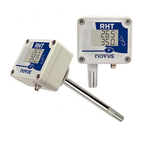
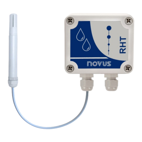
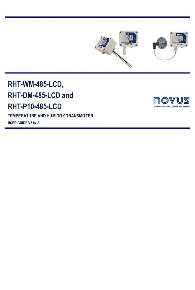
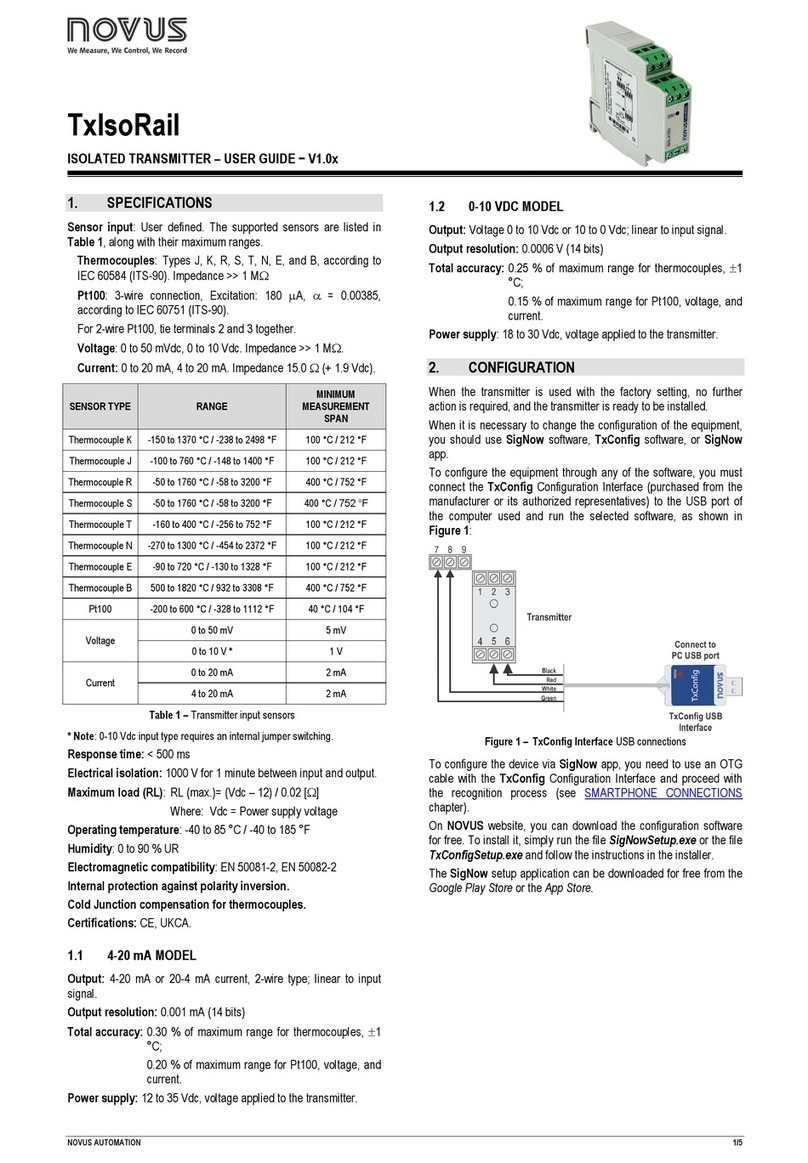
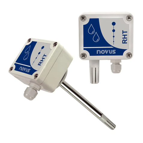
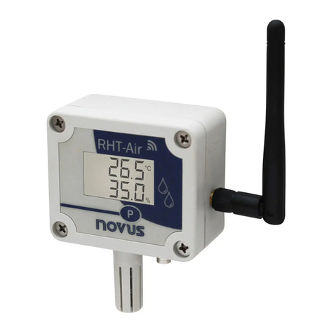
Novus RHT Climate-WM Series User manual

NOVUS AUTOMATION 1/48
RHT
Climate
Transmitter
WM and DM models
INSTRUCTION MANUAL V1.2x A
Applies to devices with firmware version starting with V1.2x.

NOVUS AUTOMATION 2/48
1SAFETY ALERTS ..................................................................................................................................................................................................3
2INTRODUCTION....................................................................................................................................................................................................4
3IDENTIFICATION...................................................................................................................................................................................................5
3.1 MODELS WITHOUT DISPLAY.......................................................................................................................................................................5
3.2 MODELS WITH DISPLAY ..............................................................................................................................................................................5
3.3 DEVICE MODELS...........................................................................................................................................................................................6
4DISPLAY INDICATIONS........................................................................................................................................................................................7
4.1 HOME SCREEN .............................................................................................................................................................................................7
4.2 DISPLAYING MAXIMUM AND MINIMUM VALUES......................................................................................................................................7
4.3 DISPLAYING OTHER PSYCHROMETRIC PROPERTIES...........................................................................................................................7
4.4 SIGNALS.........................................................................................................................................................................................................8
5INSTALLATION......................................................................................................................................................................................................9
5.1 MECHANICAL INSTALLATION .....................................................................................................................................................................9
5.1.1 DIMENSIONS .......................................................................................................................................................................................9
5.1.1.1 RHT Climate TRANSMITTER (WM MODEL) ............................................................................................................................... 9
5.1.1.2 RHT Climate TRANSMITTER (DM MODEL) .............................................................................................................................. 10
5.1.2 REMOVING AND INSTALLING THE FRONT COVER.....................................................................................................................10
5.2 ELECTRICAL INSTALLATION.....................................................................................................................................................................11
5.2.1 RECOMMENDATIONS FOR INSTALLATION ..................................................................................................................................11
5.2.2 SPECIAL PRECAUTION....................................................................................................................................................................11
5.2.3 ELECTRICAL CONNECTIONS..........................................................................................................................................................11
5.2.4 USB CONNECTION ...........................................................................................................................................................................11
5.3 SENSOR MAINTENANCE ...........................................................................................................................................................................11
5.3.1 PRECAUTIONS WITH SENSORS.....................................................................................................................................................11
5.3.2 SENSOR REPLACEMENT ................................................................................................................................................................12
6PARAMETER CYCLES .......................................................................................................................................................................................13
7CONFIGURATION...............................................................................................................................................................................................14
7.1 ANALOG OUTPUTS 0VT1 / 0VT2 .............................................................................................................................................................14
7.2ALARM OUTPUTS ALM1 / ALM2 ................................................................................................................................................................15
7.3 BUZZER CONFIGURATION CYCLE...........................................................................................................................................................19
7.4 HMI CONFIGURATION CYCLE...................................................................................................................................................................21
7.5 DIAGNOSTIC CYCLE...................................................................................................................................................................................23
7.6 COMMUNICATION CYCLE..........................................................................................................................................................................24
7.7 GENERAL CONFIGURATION CYCLE........................................................................................................................................................25
7.8 INFORMATION CYCLE................................................................................................................................................................................27
8PARAMETERS MAP............................................................................................................................................................................................28
9USB INTERFACE.................................................................................................................................................................................................29
10 SERIAL COMMUNICATION................................................................................................................................................................................30
10.1 TABLE OF HOLDING REGISTER TYPE REGISTERS ..............................................................................................................................30
11 NXPERIENCE SOFTWARE................................................................................................................................................................................36
11.1 INSTALLING NXPERIENCE ........................................................................................................................................................................36
11.2 RUNNING NXPERIENCE.............................................................................................................................................................................36
11.3 CONFIGURING THE DEVICE WITH NXPERIENCE..................................................................................................................................36
11.3.1 GENERAL PARAMETERS.................................................................................................................................................................38
11.3.2 INPUT PARAMETERS .......................................................................................................................................................................38
11.3.3 OUTPUT PARAMETERS ...................................................................................................................................................................39
11.3.4 HMI PARAMETERS............................................................................................................................................................................41
11.3.5 FINALIZATION PARAMETERS .........................................................................................................................................................43
11.4 DIAGNOSTICS..............................................................................................................................................................................................44
11.4.1 INPUT DIAGNOSTICS .......................................................................................................................................................................44
11.4.2 OUTPUT DIAGNOSTICS...................................................................................................................................................................45
12 TECHNICAL SPECIFICATIONS .........................................................................................................................................................................46
13 WARRANTY.........................................................................................................................................................................................................47
14 APPENDIX I – NOTIONS ABOUT PSYCHROMETRY.......................................................................................................................................48
NOVUS AUTOMATION 3/48
1SAFETY ALERTS
The symbols below are used in the device and throughout this manual to draw the user’s attention to important information related to device safety
and use.
CAUTION
Read the manual fully before installing and
operating the device.
CAUTION OR HAZARD
Risk of electric shock.
ATTENTION
Material sensitive to static charge. Check
precautions before handling.
All safety recommendations appearing in this manual must be followed to ensure personal safety and prevent damage to the instrument or system.
If the instrument is used in a manner other than that specified in this manual, the device’s safety protections may not be effective.

NOVUS AUTOMATION 4/48
2INTRODUCTION
RHT
Climate
Transmitters Wall Mount (WM) and Duct Mount (DM)models incorporate high-precision, stable sensors for measuring temperature
and relative humidity. Being microprocessed devices, they allow full configuration via USB or RS485 interface via a Modbus RTU command.
NXperience allows the configuration of all the resources of the device, as well as the diagnosis of the analyzed information.
Apart from the temperature and relative humidity values, which are read directly from the sensor, the transmitter calculates the value of the
following psychrometric properties1:
•Dew Point Temperature;
•Wet Bulb Temperature;
•Absolute Humidity;
•Frost Point Temperature;
•Specific Enthalpy;
•Partial Vapor Pressure;
•Mixture Ratio.
Any variable read by the sensor or calculated by the device can be transmitted via one of the two available analog outputs. You are also allowed to
configure the electrical operating level of each output:
•0-10 V;
•4-20 mA.
Two digital outputs with alarm or control functions can be related to any variable read or calculated by RHT
Climate
Transmitter.
The following options are also available:
•RS485;
•Display with Backlight;
•Audible signal.
It is important that you read carefully the manual before using this device and check that the versions of the manual and the device match. The
firmware version number is displayed at the moment the device is powered on.
1Psychrometry is the study of thermodynamic properties of dry air and water vapor mixtures. Obtaining the psychrometric properties is crucial in the psychrometric
processes of air conditioning, refrigeration, cooling and freezing, air humidification and dehumidification, drying and dehydration of humid devices, as well as in
environmental and meteorological control.

NOVUS AUTOMATION 5/48
3IDENTIFICATION
3.1 MODELS WITHOUT DISPLAY
Fig. 01 – Device without display
3.2 MODELS WITH DISPLAY
Fig. 02 – Device with display
Fig. 03 – Display indications

NOVUS AUTOMATION 6/48
Key :Key used to advance the parameters and parameters cycles. A short touch advances parameters within a cycle. A long touch advances
parameters cycles.
Key :Key used to decrease parameters. A long touch when displaying the home screen performs the action linked to the second function of the key:
•None;
•Clears registered minimum and maximum values.
Key :Key used to increase parameters. A long touch when displaying the home screen performs the action linked to the second function of the key:
•None;
•Mutes buzzer;
•Mutes buzzer and turns off the alarm outputs.
3.3 DEVICE MODELS
The RHT
Climate
Transmitter line is available in various device configurations to adapt perfectly to multiple market needs:
•Wall Mount Model (WM): Recommended for wall mounting.
•Duct Mount Model (DM): Recommended for duct mounting. DM models are available with a stainless steel (S) sensor probe and with lengths of
150 mm, 250 mm or 400 mm.
The table below shows all available models:
Model RS485 Display Stainless Steel
Probe
RHT Climate-WM
RHT Climate-WM-485-LCD
RHT Climate-WM-485
RHT Climate-DM-150S
150 mm
RHT Climate-DM-150S-485
150 mm
RHT Climate-DM-150S-485-LCD
150 mm
RHT Climate-DM-250S 250 mm
RHT Climate-DM-250S-485
250 mm
RHT Climate-DM-250S-485-LCD
250 mm
RHT Climate-DM-400S
400 mm
RHT Climate-DM-400S-485 400 mm
RHT Climate-DM-400S-485-LCD
400 mm
Table 01 – Available RHT
Climate
models

NOVUS AUTOMATION 7/48
4DISPLAY INDICATIONS
4.1 HOME SCREEN
The home screen displays three lines: line 1 displays the temperature read by the sensor, line 2 displays the value of relative humidity and finally line 3
displays the value of the option selected when configuring the device.
Fig. 04 - Home screen
4.2 DISPLAYING MAXIMUM AND MINIMUM VALUES
To navigate to the secondary screens, you need to press the key with a short touch from the home screen. With each short touch of the key,
the display will show the following screens:
Fig. 05 - Maximum and minimum temperature Fig. 06 - Maximum and minimum relative humidity Fig. 07 - Maximum and minimum dew point
temperature
On the central line, the display will show the name of the variable to which the maximum and minimum values refer:
•
T
: Temperature;
•
rk
: Relative humidity;
•
td
: Dew point.
On the upper line of the display is the MAX symbol, followed by the maximum value for that magnitude. On the lower line of the display is the MIN
symbol, followed by the minimum value. If no key is pressed for 15 seconds, the display will return to the home screen.
4.3 DISPLAYING OTHER PSYCHROMETRIC PROPERTIES
After the screens of maximum and minimum values, are available screens for viewing other psychrometric variables. The device will advance one
screen each short touch of the key , respecting the following sequence:
Fig. 08 - Wet bulb temperature Fig. 09 - Absolute humidity Fig. 10 - Frost point temperature

NOVUS AUTOMATION 8/48
Fig. 11 - Specific enthalpy Fig. 12 - Partial vapor pressure Fig. 13 - Mixture ratio
4.4 SIGNALS
•ALM + 1: Indicates that the alarm 1 output is in alarm condition.
•ALM + 1 flashing: Indicates that the alarm 1 output is in alarm condition, but the output is disabled due to overcurrent protection.
•ALM + 2: Indicates that the alarm 2 output is in alarm condition.
•ALM + 2 flashing: Indicates that the alarm 2 output is in alarm condition, but the output is disabled due to overcurrent protection.
•BUZZER: The buzzer may be activated in three conditions:
oBUZZER output alarm;
oALM1 output alarm if the buzzer is enabled in alarm 1 configurations;
oALM2 output alarm if the buzzer is enabled in alarm 2 configurations.
•USB: Indicates that the device is connected to a USB port.
•COM flashing: Indicates that the device is responding to a data request or command.
•
nnnn
: Indicates that the value to be displayed on one of the lines is above the display limit.
•
vvvv
: Indicates that the value to be shown on one of the lines is below the display limit

NOVUS AUTOMATION 9/48
5INSTALLATION
5.1 MECHANICAL INSTALLATION
The RHT
Climate
Transmitter WM model was designed to be secured to a wall by two mounting holes on the transmitter, as shown in Fig. 14.
Mounting should follow the sequence of steps below:
•Use the device’s perforation template to mark the position of transmitter mounting bore holes;
•Make the two holes using a drill with bit number 6. The bore holes should be deeper than the size of bushings;
•Insert bushings in holes. Bushings should be completely inserted into the wall;
•Position the transmitter on the wall, aiming to align with the perforations, and use bolts to secure it to the wall.
Bolts and bushings do not come with the device.
The device should be mounted with the sensor capsule facing downward to ensure the specified precision and protection
rating.
Fig. 14 – Mechanical Installation
The RHT
Climate
Transmitter DM model it is mounted via a flange. First the flange is mounted on the duct wall, then the transmitter rod is inserted
into the central bore hole on the flange and secured.
5.1.1 DIMENSIONS
5.1.1.1 RHT
Climate
TRANSMITTER (WM MODEL)
Fig. 15 – Dimensions of WM model

NOVUS AUTOMATION 10/48
5.1.1.2 RHT
Climate
TRANSMITTER (DM MODEL)
Fig. 16shows the flange dimensions and perforation:
Fig. 16 - Flange for mounting DM model
The rods for these models are made of stainless steel, with lengths of 150, 250 or 400 mm.
Fig. 17 – Dimensions of DM model
5.1.2 REMOVING AND INSTALLING THE FRONT COVER
To remove the front cover, insert a screwdriver. It is necessary to fit in the lateral handles and to force it lightly until realizing its release. The
procedure should be repeated on each of the side handles of the device, as shown in the figures below. With all sides clear, the cover can be easily
removed:
Fig. 18 - Removing the front cover of the transmitter
Fig. 19 - Removing the front cover of the transmitter
To install, fit the cover onto the base by pressing it with care to fully secure the transmitter, as shown in the figure below:
Fig. 20 - Device cover fitting

NOVUS AUTOMATION 11/48
5.2 ELECTRICAL INSTALLATION
5.2.1 RECOMMENDATIONS FOR INSTALLATION
•Signal conductors should run through the plant separately from the power supply and output conductors, if possible in grounded conduits.
•The power supply for electronic instruments must come from an appropriate grid for instruments.
•RC FILTERS (noise suppressor) are recommended in contactor coils, solenoids, etc.
•In control applications, it’s essential to consider what could happen when some part of the system fails. The device’s internal devices do not
ensure total protection.
•Grounding helps limit the effects of noise due to electromagnetic interference (EMI). Run the grounding connection by using the grounding bolt
and the grounding plane before turning on the device.
5.2.2 SPECIAL PRECAUTION
Because the transmitter is an electronic module, it requires some care when handling:
•When opening the transmitter to connect electrical wiring, avoid contact with the electronic circuit due to the risk of damage caused by static electricity.
•Pay close attention when connecting wires.
•Remember to pass all wires through a cable clip before completing electrical connections.
•When closing the housing, the cover should be placed again properly, ensuring proper sealing for this model.
5.2.3 ELECTRICAL CONNECTIONS
Fig. 21 – RHT
Climate
electrical connections
* Connector CN2 is only mounted on models that have RS485 interface (Optional).
5.2.4 USB CONNECTION
Fig. 22 – USB cable connection
5.3 SENSOR MAINTENANCE
5.3.1 PRECAUTIONS WITH SENSORS
The sensor used in the RHT
Climate
T
ransmitter is a device that is sensitive to electrostatic discharge (ESD).
Whenever the sensor is touched, measures need to be taken to prevent ESD damage.
The sensor may be damaged or lose its calibration if exposed to atmospheres contaminated with chemical
agents. Hydrochloric Acid, Nitric Acid, Sulfuric Acid and Ammonia at high concentrations can damage the
sensor. Acetone, Ethanol and Propylene Glycol can cause reversible measurement errors.
The humidity sensor’s calibration can be altered if it is exposed to contaminating vapors or extreme humidity and temperature conditions for
prolonged periods. To speed up calibration restore, proceed as described below:
•Carefully remove the sensor from the capsule, avoiding contact with bare hands (it must be removed with the use of plastic tweezers or clean
antistatic gloves);
•If there are solid particles on the sensor, wash it with deionized water at room temperature;
•Place the sensor in an oven at 120 °C (+/-10 °C) for 6 hours;
•Carefully replace the sensor in the capsule.
It is also possible to clean or dry the sensor using filtered and oil-free air, taking care that the air jets do not mechanically damage the sensor.

NOVUS AUTOMATION 12/48
5.3.2 SENSOR REPLACEMENT
In case of damage, the humidity and temperature sensor may need to be replaced. To perform this procedure, follow the steps below:
•Step 1: Disconnect the transmitter from the power supply and remove the USB cable if it is connected.
Locate the sensor's protective tip.
This example shows the sensor replacement of an RHT
Climate
DM Transmitter. In it, the sensor is
located at the end of the rod.
•Step 2: Remove the tip by turning it counterclockwise.
•Step 3: Without the tip the sensor will be exposed. Remove it by pulling it forward to disconnect it.
•Step 4: Connect the new sensor to the rod tip connector with the aid of plastic tweezers or clean antistatic
gloves, avoiding pushing or engaging the sensor by hand only.
•Step 5: Place the protection tip again and turn it clockwise to secure it to the device.
Hold the sensor only by its terminals, using plastic tweezers or new gloves.
Do not hold the sensor by the sensor element. Do not use metal tweezers. Do
not touch the sensor without wearing gloves.

NOVUS AUTOMATION 13/48
6PARAMETER CYCLES
The configuration parameters are clustered in affinity groups, called parameter cycles. The 10 parameter cycles are:
CYCLE ACCESS
1 - Primary Cycle:
In this cycle are the screens for viewing the psychrometric variables. Unrestricted access
2 -
0vt1
Cycle:
In this cycle are the configuration parameters of the transmission 1 output.
Enables the protection
mode of these cycles
3 -
0vt2
Cycle:
In this cycle are the configuration parameters of the transmission 2 output.
4 -
ALM1
Cycle:
In this cycle are the configuration parameters of the alarm 1 output.
5 -
ALM2
Cycle:
In this cycle are the configuration parameters of the alarm 2 output.
6 -
Bv22
Cycle:
In this cycle are the configuration parameters of the buzzer.
7 -
1kM
Cycle:
In this cycle are the HMI configuration parameters.
8 -
DIAG
Cycle:
In this cycle are
the parameters for forcing values of temperature, relative humidity and transmission outputs, alarm
and buzzer.
9 -
(0m
Cycle:
In this cycle you can configure parameters related to RS485 Modbus communication.
10 -
(nfg
Cycle:
You must enter the device password to access the parameters in this cycle. The parameters
allow the selection of the
measurement units, the adjustment of the atmospheric p
ressure, besides the offsets and the digital filters for the
sensor readings. You also can enable the protection of the configuration parameters and change the password.
11 - Information Cycle:
In this cycle are displayed the serial number (
sn
) and the firmware version (
firm
) of the device.
Table 02 – Parameter cycles

NOVUS AUTOMATION 14/48
7CONFIGURATION
The RHT
Climate
Transmitter has a set of parameters that allows the configuration of its two transmission outputs and its two alarm outputs and
can assigning the psychrometric properties below to each of them. The properties can be expressed in the International System of Measures (SI) or
in the English System of Measures (US).
SI US
Psychrometric properties
Min.
Max.
Unit
Min.
Max.
Unit
Temperature (measured value)
t
-40
100
°C
-40
212
°F
Relative humidity (measured value)
rX
0
100
% RH
0
100
% RH
Dew point temperature (calculated value)
Td
-90
100
°C
-130
212
°F
Wet bulb temperature (calculated value)
tW
-40
100
°C
-40
212
°F
Absolute humidity (calculated value)
dv
0
600
g/m³
0
262
gr/ft³
Frost point temperature (calculated value)
Tf
-90
100
°C
-130
212
°F
Specific enthalpy (calculated value)
H
-40
700000
*
kJ/kg
-18
300945
*
BTU/lb
Partial vapor pressure (calculated value)
E
0
1035
mbar
0
15
psi
Mixture ratio (calculated value)
R
0
260000*
g/kg
0
1820000*
gr/lb
Temperature and relative humidity are the only variables that are measured directly from the sensor that comes with the device.
All other measurements are obtained via algorithms that can lead to slight variations in relation to the real values.
Table 03 – Psychrometric properties
7.1 ANALOG OUTPUTS
0VT1
/
0VT2
The configuration cycle for analog outputs 1 and 2 allows you to assign:
•The psychrometric property associated with the output;
•The default electrical output;
•The value to be shown in case of error in the sensor reading;
•The excursion range of the transmitted psychrometric property.
Note: When the lower limit is defined with a value higher than the higher limit, the output current operates from 20-4 mA to 10-0 V.
7.1.1 Psychrometric property to be transmitted by analog outputs
0vt1
/
0vt2
It allows you to configure the psychrometric property to be transmitted by the analog outputs
0vt1
/
0vt2
.
0vt1
mEAs
0vt2
mEAs
Psychrometric property to be transmitted
Default:
off
Outputs
0vt1
/
0vt2
off
oFF
Temperature
t
Relative humidity
rk
Dew point temperature
Td
Wet bulb temperature
tW
Absolute humidity
du
Frost point temperature
Tf
Specific enthalpy
H
Partial vapor pressure
E
Mixture ratio
R
Table 04 – Psychrometric property to be transmitted
7.1.2 Operating mode for analog outputs
0vt1
/
0vt2
It allows you to configure the type of electric signal to be used by the analog outputs
0vt1
/
0vt2
.
0vt1
modE
0vt2
modE
Type of signal from analog outputs
0vt1
/
0vt2
Default:
4-20
Analog output 1 operating in mode 4-20 mA
4-20
Analog output 1 operating in mode 0-10 V
0-10
Table 05 – Type of signal from analog outputs

NOVUS AUTOMATION 15/48
7.1.3 Lower limit of the transmission range from analog outputs
0vt1
/
0vt2
It allows you to configure the lower background scale for analog outputs
0vt1
/
0vt2
.
SI US
0vt1
L-Lo
0vt2
L-Lo
Lower limit of the transmission range from analog
outputs
0vt1
/
0vt2
Min. Max. Unit Default Min. Max. Unit Default
Temperature
t
-40
100
°C
-40
-40
212
°F
-40
Relative humidity
rk
0
100
% RH
0
0
100
% RH
0
Dew point temperature
td
-90
100
°C
-90
-130
212
°F
-130
Wet bulb temperature
tW
-40
100
°C
-40
-40
212
°F
-40
Absolute humidity
du
0
600
g/m³
0
0
262
gr/ft³
0
Frost point temperature
tF
-90
100
°C
-90
-130
212
°F
-130
Specific enthalpy
h
-
40
700000
*
kJ/kg
-40
-18
300945
*BTU/lb
-18
Partial vapor pressure
E
0
1035
mbar
0
0
15
psi
0
Mixture ratio
r
0
260000*
g/kg
0
0
1820000*
gr/lb
0
Table 06 – Lower limit of the transmission range from analog outputs
*These values extrapolate the maximum value that can be shown by the display. Using the HMI, you can set up to the limit of 19999. When configured via NXperience, these parameters
can be adjusted up to the values shown on the table above, but when accessing these parameters via the HMI, they will display the value
nnnn
.
7.1.4 Upper limit of the transmission range from analog outputs
0vt1
/
0vt2
It allows you to configure the upper background scale for analog outputs
0vt1
/
0vt2
.
SI
US
0vt1
L-ki
0vt2
l-ki
Upper limit of the transmission range from
analog outputs
0vt1
/
0vt2
Min. Max. Unit Default Min. Max. Unit Default
Temperature
-40
100
°C
100
-40
212
°F
212
Relative humidity
0
100
% RH
100
0
100
% RH
100
Dew point temperature
-90
100
°C
100
-130
212
°F
212
Wet bulb temperature
-40
100
°C
100
-40
212
°F
212
Absolute humidity
0
600
g/m³
600
0
262
gr/ft³
262
Frost point temperature
-90
100
°C
100
-130
212
°F
212
Specific enthalpy
-40
700000
*
kJ/kg
700000
*
-18
300945
*BTU/lb
300945
*
Partial vapor pressure
0
1035
mbar
1035
0
15
psi
15
Mixture ratio
0
260000
*
g/kg
260000
*
0
1820000
*
gr/lb
1820000
*
Table 07 – Upper limit of the transmission range from analog outputs
*These values extrapolate the maximum value that can be shown by the display. Using the HMI, you can set up to the limit of 19999. When configured via NXperience, these parameters
can be adjusted up to the values shown on the table above, but when accessing these parameters via the HMI, they will display the value
nnnn
.
7.1.5 Status of analog outputs
0vt1
/
0vt2
in case of sensor error
It allows you to configure the status of analog outputs
0vt1
/
0vt2
in case of error in the sensor reading.
0vt1
Err
0vt2
err
Value of analog outputs
0vt1
/
0vt2
in case of error Default:
lo
Sets analog outputs
0vt1
/
0vt2
to the minimum value in case of error in the sensor reading.
lo
Sets the analog outputs
0vt1
/
0vt2
to the maximum value in case of error in the sensor reading.
Xi
Table 08 – Value of analog outputs
0vt1
/
0vt2
in case of error
7.2 ALARM OUTPUTS
ALM1
/
ALM2
All models of RHT
Climate
Transmitters have two alarm outputs, which can also be used with ON/OFF control outputs. For models with display,
there is the additional feature of an internal buzzer for audible signaling. For each alarm output and for the buzzer, the following can be configured:
•The associated psychrometric property;
•Alarm type
Lo
,
ki
,
L--k
,
-Lk-
;
•The setpoints;
•Hysteresis;
•Output condition in case of sensor error;
•And the timing.

NOVUS AUTOMATION 16/48
The configuration cycle for alarms
alm1
/
alm2
allows for assigning the psychrometric property associated with alarm outputs
alm1
/
alm2
, the
operating mode for alarms
alm1
/
alm2
(type of alarm), activation points for alarms
alm1
/
alm2
, their timing values, inhibition of alarm condition
when turning the device on, and the alarm activation mode in case of sensor reading error.
The figure below shows how the alarm outputs are activated and deactivated according to the type of alarm selected.
Fig. 23 - Alarm output activation and deactivation
The RHT
Climate
Transmitter allows for four timing options for its alarm outputs and for the buzzer:
•Normal operation;
•Activation for set time;
•Delay in activation;
•Intermittent activation.
The figures in Table 4 show the behavior of alarm outputs with these activation variations defined by the
T0n
and
T0ff
time intervals.
OPERATION
T0n
T0ff
ACTUATION
Normal operation 0 0
Alarm Event
Alarm
Output
Activation with
set time 1 to 6500 s 0
Alrm Event
Alarm
Output
T0n
Delayed
activation 0 1 to 6500 s
Alarm Event
Alarm
Output
toff
Intermittent activation 1 to 6500 s 1 to 6500 s
Alarm Event
Alarm
Output
T0n
T0ff
T0n
Table 09 - Timing functions for alarms
The Initial Blocking option prevents alarm activation if there is an alarm condition when the controller is turned on. The alarm is only enabled after
the process passes through a non-alarm condition.
The initial block is useful, for example, when one of the alarms is configured as minimum value alarm, potentially setting off the alarm right when
the process is started up, which is often undesirable behavior.
Initial blocking is not valid for the Sensor Open function.

NOVUS AUTOMATION 17/48
7.2.1 Psychrometric property associated with alarms
ALM1
/
ALM2
It allows you to configure a psychrometric property that will be associated with alarms
ALM1
/
ALM2
.
ALm1
mEAs
ALm2
mEAs
Psychrometric property associated with alarms
ALM1
/
ALM2
Default:
t
Temperature
t
Relative humidity
rk
Dew point temperature
Td
Wet bulb temperature
tW
Absolute humidity
du
Frost point temperature
Tf
Specific enthalpy
H
Partial vapor pressure
E
Mixture ratio
R
Table 10 – Psychrometric property associated with alarms
ALM1
/
ALM2
7.2.2 Activation mode for alarms
ALM1
/
ALM2
It allows you to turn off alarms
ALM1
/
ALM2
or configure them to operate as one of the alarm types indicated below:
ALm1
modE
ALm2
modE
Activation mode for alarm outputs
ALM1
/
ALM2
Default:
off
Off
oFF
Sets off alarm in case of sensor error
iErr
Sets off alarm below setpoint
SPLo
Lo
Sets off alarm above setpoint
SPki
ki
Sets off alarm between
SPLo
and
SPki
L--k
Sets off alarm below
SPLo
and above
SPki
-Lk-
Table 11 – Activation mode for alarm outputs
ALM1
/
ALM2
7.2.3 Lower Setpoint for activating alarms
ALM1
/
ALM2
It allows you to configure the set point for alarm types
Lo
,
L--k
and
-Lk-
.
SI US
ALm1
spLo
ALm2
spLo
Setpoint lower than alarm outputs
ALM1
/
ALM2
Min. Max. Unit Default Min. Max. Unit Default
ALM1
/
ALM2
for temperature
-40
100
°C
-40
-40
212
°F
-40
ALM1
/
ALM2
for relative humidity
0
100
% RH
0
0
100
% RH
0
ALM1
/
ALM2
for dew point temperature
-90
100
°C
-90
-130
212
°F
-130
ALM1
/
ALM2
for wet bulb temperature
-40
100
°C
-40
-40
212
°F
-40
ALM1
/
ALM2
for absolute humidity
0
600
g/m³
0
0
262
gr/ft³
0
ALM1 / ALM2
for frost point temperature
-90
100
°C
-90
-130
212
°F
-130
ALM1
/
ALM2
for specific enthalpy
-40
700000
*
kJ/kg
-40
-18
300945
*BTU/lb
-18
ALM1
/
ALM2
for partial vapor pressure
0
1035
Mbar
0
0
15
psi
0
ALM1
/
ALM2
for mixture ratio
0
260000*
g/kg
0
0
1820000*
gr/lb
0
Table 12 – Setpoint lower than alarm outputs
ALM1
/
ALM2
*These values extrapolate the maximum value that can be shown by the display. Using the HMI, you can set up to the limit of 19999. When configured via NXperience, these parameters
can be adjusted up to the values shown on the table above, but when accessing these parameters via the HMI, they will display the value
nnnn
.

NOVUS AUTOMATION 18/48
7.2.4 Higher Setpoint for activating alarms
ALM1
/
ALM2
It allows you to configure the setpoint for alarm types
ki
,
L--k
and
-Lk-
.
SI US
ALm1
spHi
ALm
2
spki
Setpoint higher than alarm outputs
ALM1
/
ALM2
Min.
Max.
Unit
Default
Min.
Max.
Unit
Default
ALM1
/
ALM2
for temperature
-40
100
°C
100
-40
212
°F
212
ALM1
/
ALM2
for relative humidity
0
100
%
RH
100
0
100
% RH
100
ALM1
/
ALM2
for dew point temperature
-90
100
°C
100
-
130
212
°F
212
ALM1
/
ALM2
for wet bulb temperature
-40
100
°C
100
-40
212
°F
212
ALM1
/
ALM2
for absolute humidity
0
600
g/m³
600
0
262
gr/ft³
262
ALM1
/
ALM2
for frost point temperature
-90
100
°C
100
-
130
212
°F
212
ALM1
/
ALM2
for specific enthalpy
-40
700000
*
kJ/kg
700000
*
-18
300945
*BTU/lb
300945
*
ALM1
/
ALM2
for partial vapor pressure
0
1035
mbar
1035
0
15
psi
15
ALM1
/
ALM2
for mixture ratio
0
260000*
g/kg
260000*
0
1820000*
gr/lb
1820000*
Table 13 – Setpoint higher than alarm outputs
ALM1
/
ALM2
*These values extrapolate the maximum value that can be shown by the display. Using the HMI, you can set up to the limit of 19999. When configured via NXperience, these parameters
can be adjusted up to the values shown on the table above, but when accessing these parameters via the HMI, they will display the value
nnnn
.
7.2.5 Hysteresis for turning off alarms
ALM1
/
ALM2
It allows you to adjust the differential for turning off alarms
ALM1
/
ALM2
.
SI US
ALm1
kyst
Alm2
kyst
Output hysteresis of alarms
ALM1
/
ALM2
Min.
Max.
Unit
Default
Min.
Max.
Unit
Default
ALM1
/
ALM2
for temperature
0
20
°C
0
0
20
°F
0
ALM1
/
ALM2
for relative humidity
0
20
% RH
0
0
20
% RH
0
ALM1
/
ALM2
for dew point temperature
0
20
°C
0
0
20
°F
0
ALM1 / ALM2
for wet bulb temperature
0
20
°C
0
0
20
°F
0
ALM1
/
ALM2
for absolute humidity
0
20
g/m³
0
0
20
gr/ft³
0
ALM1
/
ALM2
for frost point temperature
0
20
°C
0
0
20
°F
0
ALM1
/
ALM2
for specific enthalpy
0
20
kJ/kg
0
0
20
BTU/lb
0
ALM1
/
ALM2
for partial vapor pressure
0
20
mbar
0
0
20
psi
0
ALM1 / ALM2
for mixture ratio
0
20
g/kg
0
0
20
gr/lb
0
Table 14 – Output hysteresis of alarms
ALM1
/
ALM2
7.2.6 Alarms
ALM1
/
ALM2
on time
Min. Max. Unit Default
ALm1
T0n
Alm2
T0n
Time of alarms on
0
6500
s
0
Table 15 – Time of alarms on
7.2.7 Alarms
ALM1
/
ALM2
off time
Min.
Max.
Unit
Default
ALm1
T0ff
Alm2
T0ff
Time of alarms off
0
6500
s
0
Table 16 – Time of alarms off

NOVUS AUTOMATION 19/48
7.2.8 Initial blocking of alarms
ALM1
/
ALM2
It allows blocking the activation of alarms
ALM1
/
ALM2
if the transmitter starts up in alarm condition.
ALm1
bLA
Alm2
bla
Initial blocking of alarms
ALM1
/
ALM2
Default:
yEs
Without initial blocking of alarms
ALM1
/
ALM2
no
With initial blocking of alarms
ALM1
/
ALM2
yEs
Table 17 – Initial blocking of alarms
ALM1
/
ALM2
7.2.9 Status of alarms
ALM1
/
ALM2
in case of sensor error
It allows you to configure the outputs from alarms
ALM1
/
ALM2
so that they are activated in case of sensor reading error.
ALm1
Err
Alm2
err
Status of alarm outputs
ALM1
/
ALM2
in case of sensor error Default:
Off
Alarms
ALM1
/
ALM2
off
oFF
Alarms
ALM1
/
ALM2
on
On
Table 18 – Status of alarm outputs
ALM1
/
ALM2
in case of sensor error
7.2.10 Enable buzzer activation linked to alarms
ALM1
/
ALM2
It allows you to enable buzzer activation linked to alarms
ALM1
/
ALM2
.
ALm1
Bv22
Alm2
Bv22
Enable buzzer for alarm outputs
ALM1
/
ALM2
Default:
Dsbl
The buzzer will
not
be activated when alarms
ALM1 / ALM2
occur.
Dsbl
The buzzer will be activated when alarms
ALM1
/
ALM2
occur.
Enbl
Table 19 – Enable buzzer for alarm outputs
ALM1
/
ALM2
7.3 BUZZER CONFIGURATION CYCLE
The buzzer configuration cycle allows for assigning the psychrometric property associated with the buzzer, the buzzer operating mode
(type of alarm), buzzer activation points, their timing values, inhibition of alarm condition when turning the device on, and the buzzer activation
mode in case of sensor reading error.
7.3.1 Psychrometric property associated with the buzzer
It allows you to configure the psychrometric property that will be associated with the buzzer.
Bv22
mEAs
Psychrometric property associated with the buzzer Default:
t
Temperature
t
Relative humidity
rk
Dew point temperature
Td
Wet bulb temperature
tW
Absolute humidity
du
Frost point temperature
Tf
Specific enthalpy
H
Partial vapor pressure
E
Mixture ratio
R
Table 20 – Psychrometric property associated with the buzzer
7.3.2 Buzzer activation mode
It allows you to turn off the buzzer or configure it to operate as one of the alarm types set forth below:
Bv22
modE
Buzzer activation mode Default:
off
Off
oFF
Activates the alarm in case of sensor error
iErr
Activates alarm below setpoint
SPLo
Lo
Activates alarm above setpoint
SPki
ki
Activates alarm between
SPLo
and
SPki
L--k
Activates alarm below
SPLo
and above
SPki
-Lk-
Table 21 – Buzzer activation mode

NOVUS AUTOMATION 20/48
7.3.3 Lower psychrometric property setpoint for buzzer activation
It allows you to configure the setpoint for alarm types
Lo
,
L--X
and
-LX-
.
SI US
Bv22
spLo
Psychrometric property
Min.
Max.
Unit
Default
Min.
Max.
Unit
Default
Temperature
-40
100
°C
-40
-40
212
°F
-40
Relative humidity
0
100
% RH
0
0
100
% RH
0
Dew point temperature
-90
100
°C
-90
-130
212
°F
-130
Wet bulb temperature
-40
100
°C
-40
-40
212
°F
-40
Absolute humidity
0
600
g/m³
0
0
262
gr/ft³
0
Frost point temperature
-90
100
°C
-90
-130
212
°F
-130
Specific enthalpy
-40
700000
*
kJ/kg
-40
-18
300945
*
BTU/lb
-18
Partial vapor pressure
0
1035
mbar
0
0
15
psi
0
Mixture ratio
0
260000
*
g/kg
0
0
1820000
*
gr/lb
0
Table 22 – Psychrometric property
*These values extrapolate the maximum value that can be shown by the display. Using the HMI, you can set up to the limit of 19999. When configured via NXperience, these parameters
can be adjusted up to the values shown on the table above, but when accessing these parameters via the HMI, they will display the value
nnnn
.
7.3.4 Higher Setpoint for buzzer activation
It allows you to configure the set point for alarm types
ki
,
L--k
and
-Lk-
.
SI US
Bv22
spki
Higher Setpoint for buzzer activation
Min.
Max.
Unit
Default
Min.
Max.
Unit
Default
Temperature
-40
100
°C
100
-40
212
°F
212
Relative humidity
0
100
% RH
100
0
100
% RH
100
Dew point temperature
-90
100
°C
100
-130
212
°F
212
Wet bulb temperature
-40
100
°C
100
-40
212
°F
212
Absolute humidity
0
600
g/m³
600
0
262
gr/ft³
262
Frost point temperature
-90
100
°C
100
-130
212
°F
212
Specific enthalpy
-40
700000
*
kJ/kg
700000
*
-18
300945
*
BTU/lb
300945
*
Partial vapor pressure
0
1035
mbar
1035
0
15
psi
15
Mixture ratio
0
260000
*
g/kg
260000
*
0
1820000
*
gr/lb
1820000
*
Table 23 – Higher Setpoint for buzzer activation
*These values extrapolate the maximum value that can be shown by the display. Using the HMI, you can set up to the limit of 19999. When configured via NXperience, these parameters
can be adjusted up to the values shown on the table above, but when accessing these parameters via the HMI, they will display the value
nnnn
.
7.3.5 Hysteresis for turning off buzzer
It allows you to adjust the differential for turning off the buzzer.
SI US
Bv22
kyst
Hysteresis for turning off buzzer
Min.
Max.
Unit
Default
Min.
Max.
Unit
Default
Temperature
0
20
°C
0
0
20
°F
0
Relative humidity
0
20
% RH
0
0
20
% RH
0
Dew point temperature
0
20
°C
0
0
20
°F
0
Wet bulb temperature
0
20
°C
0
0
20
°F
0
Absolute humidity
0
20
g/m³
0
0
20
gr/ft³
0
Frost point temperature
0
20
°C
0
0
20
°F
0
Specific enthalpy
0
20
kJ/kg
0
0
20
BTU/lb
0
Partial vapor pressure
0
20
mbar
0
0
20
psi
0
Mixture ratio
0
20
g/kg
0
0
20
gr/lb
0
Table 24 – Hysteresis for turning off buzzer
7.3.6 Buzzer on time
Min. Max. Unit Default
This manual suits for next models
13
Table of contents
Other Novus Transmitter manuals

Novus
Novus RHT-P10 User manual

Novus
Novus RHT-WM User manual

Novus
Novus TXMINI-DIN43650 User manual

Novus
Novus TxIsoRail User manual

Novus
Novus TxIsoPack-HART User manual

Novus
Novus TXMINI-M12-485 User manual

Novus
Novus NP785-50 User manual

Novus
Novus NP600 User manual

Novus
Novus DigiRail-VA User manual

Novus
Novus RHT-WM-485-LCD User manual

Novus
Novus TxRail User manual

Novus
Novus RHT-Air User manual

Novus
Novus NP785 User manual

Novus
Novus NV-202VIP User manual

Novus
Novus TxIsoPack User manual

Novus
Novus NP-430D User manual

Novus
Novus TxBlock-USB User manual

Novus
Novus TxBlock-USB User manual

Novus
Novus NVPT-131VTP-HD User manual

Novus
Novus RHT Climate WM User manual