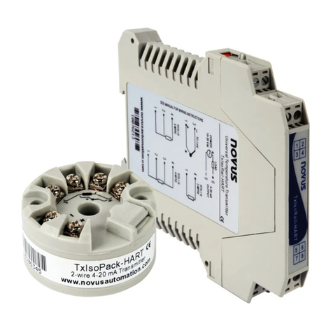
TxMini-M12-485 Transmitter
NOVUS AUTOMATION 2/5
The top menu and the fields shown in Fig.1 allows configure the
transmitter. Follow a brief description about the functions for each
option. For more details, see the Help
Help Topics option.
1. File: Option to exit DigiConfig software.
2. Configurations: Allows you to set the Communication and
Language.
- Communication: Displays a window that allows you to configure
the communication parameters of the software.
- Language: Use this menu option to choose the language for the
DigiConfig. The available languages are English, Spanish and
Portuguese.
3. Help:Displays information on Help Topics and About.
- Help Topics: Assists through a descriptive window with detailed
information about the use and parameters of compatible devices
with the DigiConfig software such as TxMini-M12-485 transmitter.
- About: Shows information about the manufacturer´s website and
DigiConfig software version.
4. Devices:This field shows the compatible devices for
DigiConfig software. After detecting a device on the Modbus
network, the software displays a corresponding access icon to the
family of devices to which it belongs and its Modbus address.
5. Search Options: This field contains the search options for the
Temporary mode, and other equipment within an address range.
- Temporary: Use to search for equipment’s in Temporary mode
with the default communication parameters.
- First Address: If you select the Start Address selection box, the
software will search a device on the network that correspond to this
address, the same baud rate and parity values as configured on
DigiConfig Communication screen.
- First and Last Address: If you select the Start Address box and
Last Address box simultaneously, the software will search devices
on the network that have addresses within this range and the same
baud rate and parity values as configured in DigiConfig
Communication screen.
TXMINI-M12-485 CONFIGURATION SETTINGS
Using DigiConfig to configure devices with default values:
STEPS
1. Run DigiConfig software (from version 1.8).
2. Click on the tab Configuration
Communication.
3. Select the serial COM port that DigiConfig will use.
Note: Select the COM port connected to the RS485 interface.
4. In the Search Options field, select the Temporary box.
5. Click the Search button:
6. If the software detect a device, it will appear in the devices tree
as a Temporary device.
7. The software will show a device with the address 247, an
empty Title field, Serial Number and Firmware Version for the
connected TxMini-M12-485 transmitter.
8. After displayed the equipment as Temporary, click the mouse
on the address (247), and will open a window for the new device
9. At the left-top of the screen, you can check in the Device
Identification field the following items:
- Title: In this field, you can enter a title up to ten characters to
identify the equipment in the devices field of the screen.
- Model: Shows the transmitter model.
- Serial Number: Shows the transmitter's serial number.
- Firmware Version: Displays the firmware version of the device.
10. In the Device Configuration field, you can check the following
items:
- Input Type: It indicates the Pt100 sensor used with the TxMini-
M12-485 transmitter.
- Offset: This field allows you to change the value read by the
temperature sensor in the range of -10 to +10 degrees.
- Filter:You can use this field to smooth the variations in the
temperature value of the readings in the Diagnostic tab, so that
the read value is more stable with lower oscillation. You can use
values from 0 to 20, with the value 0 as a default condition.
- Error Value: The default Error Value is 0, but can take values
from -9999 to 9999 according to the requirements. The software
will shows this value when there is an error in the sensor reading.
- Unit: The default Unit value is Celsius (°C), but there is the option
to display the temperature in Fahrenheit (ºF).
- Low Limit and High Limit: These fields shows the measurement
range for the Pt100 sensor. These two fields are read-only.
Fields Lower and Upper Limit are for viewing only.
Note:You can see detailed information about the function
Temporary
Duration after the Communication Settings step.
11. The Communication Settings field contains the following items:
- Address: On this field, you can define a Modbus network address
for the device selecting a number in the range of 1 to 247.
Note: The default address is 247.
- Baud Rate: On this field, you can define the communication Baud
Rate selecting one of the predefined values showed in Table 2.
4800 57600
9600 115200
Table 2 - Options available for the baud rate
- Parity: The Parity field allows the user to select one of three
available values for the parity bit. The default value is Even. The
available options are:
Parity Stop bits
None 2
Odd 1
Even 1
Table 3 - Parity bit options
Note: The choice of parity define the quantity of stop bits in
accordance with the Modbus standard.
Sending a Configuration:
1. Edit the parameters in accordance with the requirements.
2. Then click on the Apply button.
3. The software will start to send the configuration data to the
device and will show a dialog (Sending configuration to the
device...).
4. After completing the transfer, it will pop up a window that
informs the successful of the operation. Then, click OK.
Temporary Device Configuration
The temporary mode was created in case you need to change
some device settings, but do not know the previously set
communication parameters such as Baud Rate, Address or Parity.
This mode aims to keep the same communication parameters to
the default values for some time, based on Table 1. The Duration
parameter is configured with the default value of sixty seconds (60
s), and can be set in the range of 10 to 60 s according to user
needs. For further clarification, follow an example to illustrate the
use of the temporary mode and function of the parameter Duration.
Ex: The user configure the device with the following parameters:
Baud Rate: 115200;
Address: 121;
Parity: None Stop Bits: 2.
