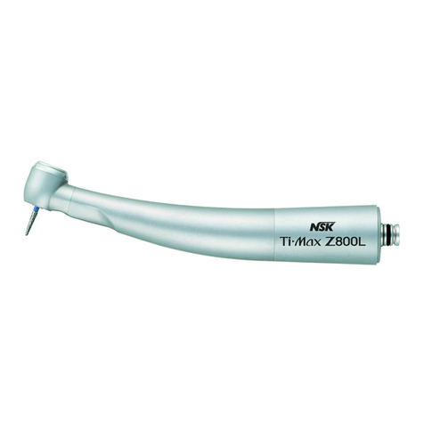
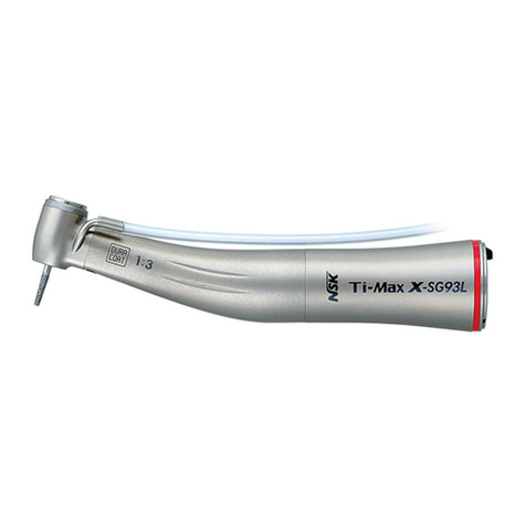
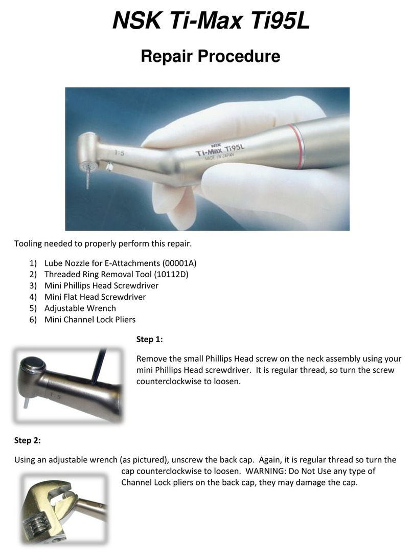
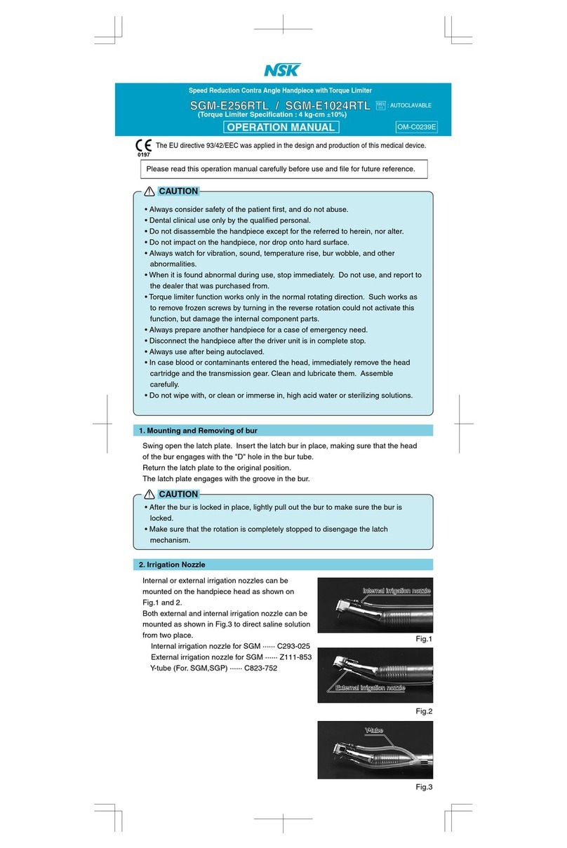
NSK Ti-Max A 500 User manual

TheTi-Maxhandpieceoutercasingismanufacturedwithadvancetechnologyandmetallagy:TITANIUM
・Titaniumisusedforitsstablity,hardnessandlightweightascomparedtoothermaterial.
・Titaniumisalsonon-allergictoaloysensitivepatient.
・TheCLEAN-HEAD(PAT.)system,incorporatedinthehandpiece,preventsuctionoforalfluidsanddebrisinapatient'smouth
intotheturbineexhaustlineofthehandpieceandtubingsofthedentalunitandenvironment.
・The NON-RETRACTION VALVE incorporated in the coupling joint end, a quick connect coupling for Ti-Max series
handpiece,effectivelypreventbackblowoforalfluidsfromthepatient,smouththroughthewatersprayoutletofthehandpiece
head.
・Water spray system is made as an integral part of the cartridge. Clogging of the water line and the spray outlet is thus
minimized.Thespraysystemisrenewedateachcartridgereplacement.
・Provisionofthesprayoutletinthecartridgebringsthesprayoutletmuchclosertothebur.
Thevisibilityangleisgreatlyimprovedevenwiththreejetspraying(PAT.).
・Ti-Maxhandpiecesareautoclavableupto135℃.
・
Improved Glass Rod Optics located at the head greatly illuminates the working area, improved visibility for diagnosis and
treatment,
causinglesseyestraintotheoperator.(A500L,A600L,A700L)
・PushbuttontypechuckingsystemULTRAPUSHcartridge.
・Twistfree,360゜rotationminimizeshosedrag.
a CouplingJointtohandpiecehose
Alignthetubesatthebackendofthecouplingwiththecorrespondingholes
inthehoseconnector.Insertthecouplingintothehoseconnectorandtighten
thehosenutbyturningitclockwise.
s ConnectingCouplingJointtothehandpiece
InsertthehandpieceintothecouplinguntilaclickisheardasshowninFig.1.
d Disconnectinghandpiecefromcouplingjoint
Whenthehandpieceistobedisconnectedfromthecouplingforautoclaving
orchangingthehandpiece,slidebackthecennectorringasshowninFig.2,
andthehandpiecepopsout.
UsingtheNSKpressuregauge,calibratethedriveairpressureto0.2−0.25MPa(2.0-2.5kgf/F)atthearrowpoint.
Ifapressuregaugeisnotavailable,thepressurecanbesetbetween0.22-0.27MPa(2.2−2.7kgf/F)atthechairsidepressure
gauge.(Fig.3)
・DONOTusenon-standardburs.TheISOstandardshankdiameterisφ1.59−1.60㎜.
・DONOTusebent,worn,ordamagedburs.
・Alwaysusecleanburs.Uncleanedbursmaycauseunwantedamountofpressureonthechuck.
・Insertaburallthewayintothechuckuntilitstops.
・DONOTuseshortshankbursinSTANDARDorTORQUEhandpiece.
・UseshortshankbursinMiniheadhandpiece(A500,A500L).
a RemovingBurs
Pushthepushbuttonintheheadcapwiththumbtoclick,andremovethebur.(Fig.4)
*Note:Pushbuttonspringisofadoubleaction.Pushuntilthebuttonisinflushwiththeheadcap.(Fig.5)
s MountingBurs
Inserttheburintotheheaduntilitstops(4-5adeep).Pushthepushbuttonandfurtherinserttheburallthewayintothe
headuntilitstops.
Aftertheburisheldinplaceinthechuck,pushtheburfurtherintothechuck
beforeuse,sothatthechuckgrippowerwillincrease.(Fig.6)
SupplyPANASPRAYor/andCare3Plusaftereachuseand/orbeforeautoclaving.
■PANASPRAY(Fig.6)
① AttachthePHATELUSnozzleintothesprayoutletofPANA-SPRAY.
② InsertthePHATELUSnozzleintothehandpiecebackend.
③ Sprayfor1−2seconds.Holdthespraycanupright.
(Fig.7)
■Care3Plus
NSKCare3Plusautomatichandpiececleaningandlubricationsystem
Afterconnectingthehandpiecetothecorrectadaptor,activatetheCare3systemper
theCare3Systeminstructions.
! CAUTIONS
1.
2.Features
3.Specifications
4.ConnecttheCouplingJoint
5.DriveAirPressure
6. CautionsonBurs
7.ChangingBurs
!
8.Lubrication
A500/A500L
A600/A600L
A700/A700L
OM-T0127E
OPERATIONMANUAL
0197 PleasereadthisOperationManualcarefullybeforeuseandfileforfuturereference.
TheEUdirective93/42/EECwasappliedinthedesignandproductionofthismedicaldevice.
Type
Rotation
DriveAirPressure
HeadDiameter
HeadHeight
Weight(Head)
ChuckType
SprayType
Light
BurSize
A500
*
380,000-450,000min
-1
(rpm)
0.2-0.25MPa
(2.0-2.5kgf/F)
φ10.3㎜
11.3㎜
41g
PushButtonType
TripleSpray
-
φ1.59-φ1.60
ShortShankBur
A600
*
380,000-450,000min
-1
(rpm)
0.2-0.25MPa
(2.0-2.5kgf/F)
φ11.2㎜
14.4㎜
42g
PushButtonType
TripleSpray
-
φ1.59-φ1.60
Std.Bur
A700
*
300,000-380,000min
-1
(rpm)
0.2-0.25MPa
(2.0-2.5kgf/F)
φ13.2㎜
14.6㎜
44g
PushButtonType
TripleSpray
-
φ1.59-φ1.60
Std.Bur
A500L
*
380,000-450,000min
-1
(rpm)
0.2-0.25MPa
(2.0-2.5kgf/F)
φ10.3㎜
11.3㎜
44g
PushButtonType
TripleSpray
GlassRodOptics
φ1.59-φ1.60
ShortShankBur
A600L
*
380,000-450,000min
-1
(rpm)
0.2-0.25MPa
(2.0-2.5kgf/F)
φ11.2㎜
14.4㎜
44g
PushButtonType
TripleSpray
GlassRodOptics
φ1.59-φ1.60
Std.Bur
A700L
*
300,000-380,000min
-1
(rpm)
0.2-0.25MPa
(2.0-2.5kgf/F)
φ13.2㎜
14.6㎜
46g
PushButtonType
TripleSpray
GlassRodOptics
φ1.59-φ1.60
Std.Bur
*Speedmayslightlyvarydependingontheback-endconfigurationandtypeofhoseused.
Fig.1
Fig.2
DONOTslidebacktheconnectorringwhilethehandpieceisunderair
pressure.Thehandpiecemaybeejectedfromthecouplingasaresult
ofthepressurization.
DONOTexceedtherecommendedairpressure
topreventprematureballbearingfailure.
Incaseacuttingisperformedunderheavyvibrationssuchasincrownremoval,theremaybeacasewherethebur
getsstuckinthehead.
Pullitoutwithplierswiththepushbuttonkeptpushedhard.
Thiscasemaybepreventedifyouoftenchangethepositionoftheburinthechuck.
Fig.3
PHATELUSNozzle
PANA-SPRAY
P183-090
Fig.7
Fig.4 Fig.5 Fig.6
・Thishandpieceisdesignedonlyfordentalclinicaluse.
・Priortoeachuse,ensurethatallinstrumentandaccessoriesmustbeinproperconditionsbeforeoperationasper
instructionsenclosed.
・Considerationforthepatient'ssafetymustbetaken,whenusingthehandpiece.
・Beforeeachuse,besurethatbursareproperlyseatedandsecuredinthehandpiece.
・Usebursfromreputablemanufactures,withISOstandardofshaftdiameterof1.59〜1.60㎜,amax.totallengthof
26㎜(1.02")(StandardorTorqueheads)andamax.headdiameterofthe2㎜(.0787").Burswhichdoesnotagree
fromthestatedmeasurementsshouldnotbeused.
・Afterextendedusethehandpiecemaybecomenoisy,replacethecartridgewithanewonemanufacturedbyNSK.
Failuretoreplacethecartridgemaycauseaccidentsorimpairoperator,shearing.
・Depressingthepush-buttonwhilehandpieceburisinrotationwillresultinOVERHEATINGofthehandpiecehead.
SpecialcautionmustbeexercisedduringusetokeepcheektissueAWAYfromthepush-buttonofthehandpiece.
Contactwithcheektissuemaycausethepush-buttontodepressandinjurytothepatientmayoccur.
・NSKturbinesshouldnotberebuiltorrecyclebyun-qualifiedNSKtechnican.Replacingormishandlingthebearings
only may result in unexpected failure causing patient injury due to different in wear factors of new vs. old
components,ormishandling.
・Bursmustbeinsertedallthewayintochuckforproperburretention.
Extendingthebur,in-stablelatycouldresultinbentburs,indequatecoolingandimpropergripoftheburresultingin
personalinjuries.
CAUTION
!
CAUTION
!
CAUTION
!
Rev.A

9.Sterilization
10.Cleanupaftereachpatient
11.ReplacingCartridge
12.ReplacingHalogenLamp
13.ReplacingwornO-ringinthehandpiece
14.Cleaningofthefiberopticend(A500L,A600L,A700L)
15.CleaningofSprayPorts
16.Non-RetractionValve
・Skipdrycycle.
・Heatingelementmaybelocatedthebottomofthechamber,andthetemperaturetherelocallymayexceedtheset
value.Placethehandpieseonthecentraloruppertray.
Sterilizationbyautoclaveisrecommended.
Sterilizationrequiredaftereachpatientasnotedbelow.
AUTOCLAVING:
① Brushoffexcessdirtandwipecleanwithalcohol-soakedcloth.
② RemovethehandpiecefromthecouplingandlubricatewithPANA-SPRAYasdescribedintheLubricationsection.
③ Insertthehandpieceinasterilizationpouchandsealit.
④ Autoclavableuptoamax.135℃.
ex.)Autoclavefor20min.at121℃,or15min.at132℃.
⑤ Keepthehandpieceintheautoclavepouchtokeepitcleanuntilyouuseit.
※ Sterilizationat121℃formorethan15minutesisrecommendedbyEN13060orEN554.
※ Performingsterilizationaccordingtoourinstructionhasminimaleffectontheinstruments.Lifespanisgenerallydetermined
bywearanddamageduetouse.
ItisimportanttocleantheslitintheheadasfollowsaftereachpatientandbeforeautoclavingtoappreciatelastingCLEAN-
HEADperformance.(Fig.8)
① BrushoffthedebrisattheslitsasshowninFig.9.
② Runthehandpieceattheratedpressure.
③ Immersehalfoftheheadincleanwaterwhilethehandpieceisrunning.
④ Runthehandpieceinthewater4−5seconds.(Fig.10)
⑤ Removethehandpiece,whilerunning,fromthewater.Stopandwipedrythehandpiece.
⑥ Lubricatebeforeautoclaving.
*Note:Changewatereachtime.
a Removingthecartridge
① Mountadummyburinthechuck.
② Setthewrenchontheheadcap,turnthewrenchcounter-clockwiseand
removethecap.(Fig.11)
③ Pushupthedummybur,andthecartridgeiseasilyremovedfromthehead.
④ Cleantheheadinterior,whendirty,withPANA-SPRAY.
Fig.11
Fig.12
s Insertingthenewcartridge
① Insertthenewcartridge,withitspinalignedintheslotofthehandpiecehead,straightintothehandpiece.
② Handtightenthecapuntilfingertightandsecurewithwrenchuntilthecapsetsinplace.(Fig.12)
※OptionalCartridge:Ti-MU03(CartridgeforMiniaturehead)OrderNo.P057
Ti-SU03(CartridgeforStandardhead)OrderNo.P058
Ti-TU03(CartridgeforTorquehead)OrderNo.P059
Fig.13
・Theheadcapscrewthreadisveryfine.Topreventitfrombreaking,useofthe
wrenchfromthefirstthreadisnotrecommended.
・Beforeinsertinganewcartridge,cleantheheadinterior.
・MakesurethattwoO-rings(Fig.13)areinplaceonthecartridge.
Fig.15
Ahalogenlampisinsidethequick-connectcoupling.
① Removethehandpiecefromthecoupling.
Turntheserratedringontheconnectorclockwiseandremovethebackend.
Thelampisinthebackendmember.(Fig.14)
② Pulloutthelamp.(Fig.15)
③ Insertanewlampandalignitspinswiththesocketholes.
Pushitin.(Fig.16)
④ Assembleinthereverseorder.Besuretoalignthetubesinthemale
memberwiththecorrespondingholesinthebackendmember.
Tightentheserratedringsecurely.
※OptionalLamp:PTLBulb(Packof3)OrderNo.Y900-529
Fig.17
Fig.19
① Removethehandpiecefromthecoupling.Unscrewthetaperedbodyofthehandpiecebyturningitcounter-clockwise.
(Fig.17)
② PushoutthewornO-ringwithyourthumb.(Fig.18)
③ InsertnewO-ringintheO-ringgroove.
④ Screwthetaperedbodysecurelybackontothehandpiece.(Fig.19)
Makesureitissecurelytightened.
※OptionalO-ring:PTLO-ringSet(Packof5)OrderNo.Y900-580
Fig.20Fig.20
Incasethelighthasbecomedim,cleanthefiberopticendwithanalcohol-soakedcottonswab.
(Fig.20)
Donotuseapointedtoolorsharpedgestocleanthefiberend.Theymaydamagethemirror
finishandreducethelighttransmissionefficiency.
Ifthefiberopticendhasbecomedamaged,sendthehandpiecetoyourlocaldistributorforrepair.
Whenspraynozzleareclogged,orspraydoesnotexitevenlyfromthreeports,cleantheportsasfollows:
① Removetheburorburblankfromthechuck.Removetheheadcap,andthecartridgefromthehead.
AsdiscribedintheReplacingCartridge.
② Takeoutthecleaningwirefromthebackendofthebrushholder.Insertthewirestraightintothe
spraynozzlewithcaution.Donotforciblyinsertthewireintotheport.Damagedordisorientedport
couldcausethespraydivergeordirectedawayfromthebur,andthecoolingefficiencydeteriorates.
SeeFig.21.
③ Makesurethatcleaningwirereachestothegroove,andbrushoffthedebris.
④ Afteruse,cleanthecleaningwire.Pushintothebrushholderwiththepointedendofthewire
inward.
Anon-retractionvalveisequippedintheCouplingJoint,whichshutsoffthe
waterretractionrightatthehandpiecehead,topreventoralfluidssuckedinto
thewaterline.Onceinawhile,useasyringetocheckitseffectivenessand
injectairtocleanthevalveseat.(Fig.22)
!
Airorwaterleakmayoccurifconnectionisloose.
!
Alooseconnectionmayresultinanairorwaterleak,or,insome
case,thehandpiecemaygetstuckonthecoupling.
!
Fig.8 Fig.10
Slit
Insert SerratedRing
Lamp Fig.14
Pins SocketHoles
Fig.16
Fig.15
Fig.18
CottonSwab
FiberOpticEnd
Fig.21
Note:Syringeisnotsuppliedwiththehandpiece.
Fig.22
PullPull
When the valve does not seem functioning, use the syringe and
inject air into the water tube of the back-end. Most dirt may be
blownoutoftheseat.
Toreplacethevalve,removetheback-endgasket.Pullandremove
thewatertube,andreplacetheNon-RetractionValve.(Fig.23)
Fig.23
WaterTube Non-RetractionValve
Gasket
O-rings
Fig.9
!
Slot
Wrench
Cartridge HeadCap
Pin
ThishandpiececanbewashedviaThermoDisinfector.
07.06.02◯
M
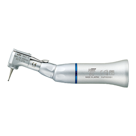
This manual suits for next models
5
Other NSK Dental Equipment manuals