NSK Surgic Pro2 User manual


1
English
English
Contents
1. User and Intended Purpose ............................... 2
2. Precautions for Handling and Operation ............. 2
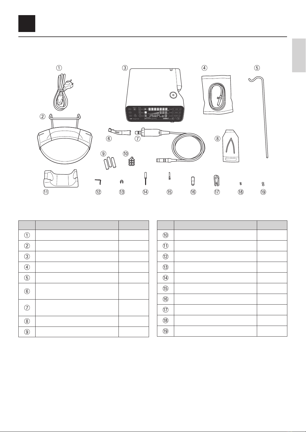
3. Product Description .......................................... 5
3–1 Package contents ������������������������������������������������������� 5
3–2 Control unit, foot control ���������������������������������������������� 6
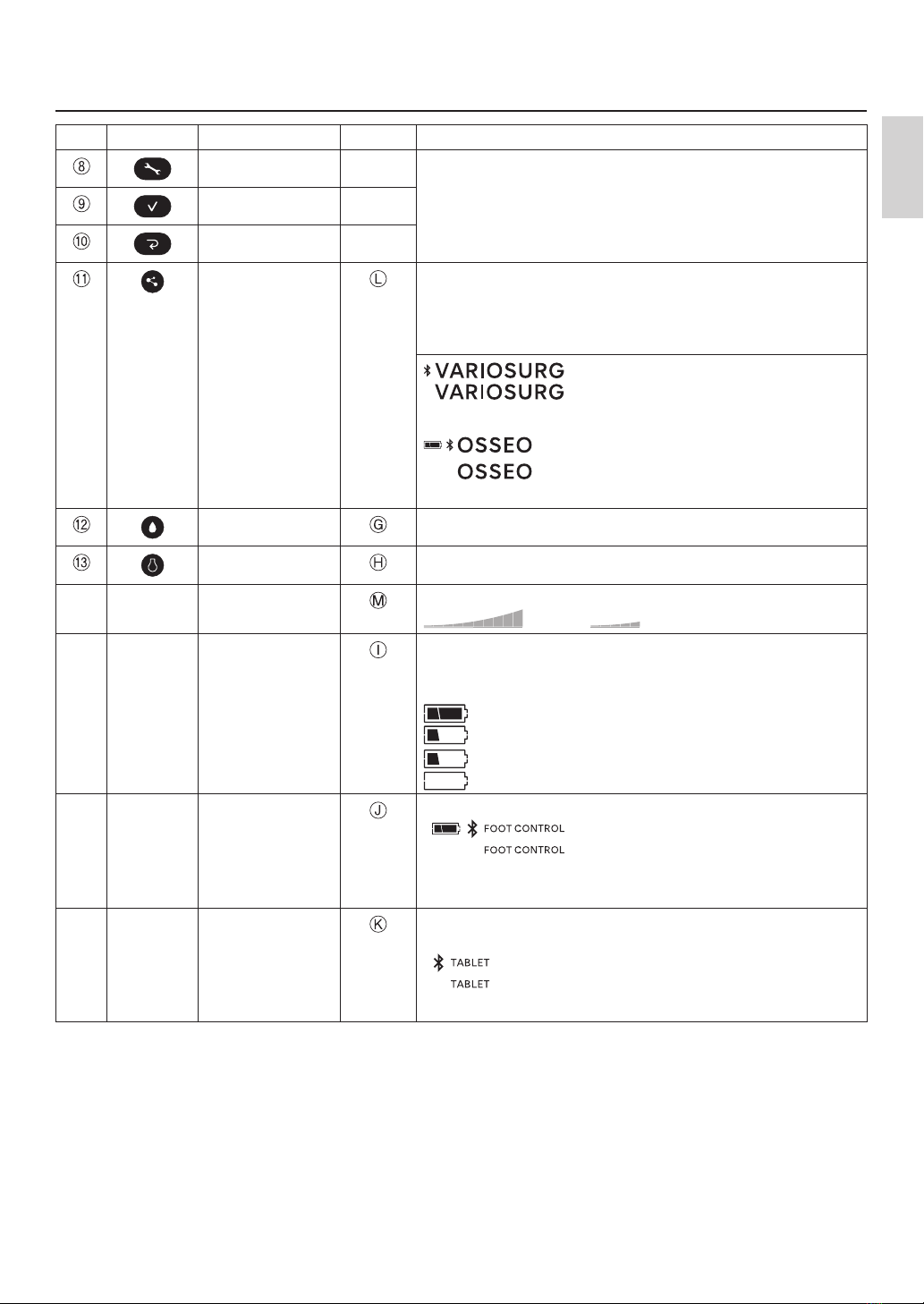
3–3 Control panel �������������������������������������������������������������� 8
4. Preparation for Use ......................................... 10
4–1 Connecting the AC power cord ����������������������������������� 10
4–2 Installing foot control batteries ����������������������������������� 10
4–3 Installing foot control hanger �������������������������������������� 11
4–4 Mounting the coolant solution hanger post ������������������ 11
4–5 Installing the irrigation tube ��������������������������������������� 12
4–6 Inserting irrigation tube into bag/bottle ������������������������ 13
4–7 Connecting the motor cord ����������������������������������������� 14
4–8 Connecting the handpiece ����������������������������������������� 14
4–9 Irrigation nozzle attachment ��������������������������������������� 15
4–10 Attaching the tube holder ������������������������������������������ 15
4–11 Check before treatment ��������������������������������������������� 15
5. Operation Procedure ....................................... 17
5–1 Calibration function ��������������������������������������������������� 17
5–2 Starting operation ����������������������������������������������������� 20
5–3 Protection circuit ������������������������������������������������������ 21
5–4 Sleep mode �������������������������������������������������������������� 21
5–5 Link function ������������������������������������������������������������ 22
6. Post-use Maintenance .................................... 26
6–1 Preparation for maintenance �������������������������������������� 26
6–2 Cleaning and disinfection ������������������������������������������� 26
6–3 Sterilization �������������������������������������������������������������� 29
6–4 Storage �������������������������������������������������������������������� 29
7. Maintenance .................................................. 30
7–1 Replace the O-ring ���������������������������������������������������� 30
7–2 Periodical maintenance checks ���������������������������������� 30
7–3 Foot control calibration ���������������������������������������������� 31
8. Setting ........................................................... 32
8–1 Setting key ��������������������������������������������������������������� 32
8–2 Implant system ��������������������������������������������������������� 37
8–3 Programming the system operation ����������������������������� 38
9. Troubleshooting .............................................. 40
9–1 Error code ���������������������������������������������������������������� 40
9–2 Problems and solutions ��������������������������������������������� 41
10. Contra Angle Handpieces, Spare Parts and
Optional Parts ................................................ 44
10–1 Contra angle handpieces ������������������������������������������� 44
10–2 Spare parts list ��������������������������������������������������������� 44
10–3 Optional parts list ����������������������������������������������������� 45
10–4 Compatible terminals ������������������������������������������������ 45
11. Specifications ................................................ 46
11–1 Specifications ����������������������������������������������������������� 46
11–2 Bluetooth specifications ��������������������������������������������� 47
11–3 Classification of equipment ���������������������������������������� 47
11–4 Operation principle ���������������������������������������������������� 47
11–5 Warranty ������������������������������������������������������������������ 47
11–6 Disposing of products ������������������������������������������������ 47
11–7 Symbol �������������������������������������������������������������������� 48
11–8 Factory settings (Implant system) �������������������������������� 49
12. EMC Information (Electromagnetic Compatibility
Information) ................................................... 51

2
1 User and Intended Purpose
User: Qualified professional (surgeon with knowledge and skills required for operating this product)�
Intended purpose: The Surgic Pro2 is intended for use in dental oral surgery and dental implantology�
The main unit is designed to be used with a specific dental micromotor that drives dental handpieces fitted with
appropriate tools to cut hard tissues in the mouth�
2 Precautions for Handling and Operation
Read these safety cautions thoroughly before use and operate the product properly�
These indicators are to allow you to use the product safely, prevent danger and harm to you and others� These are
classified by degree of danger, damage and seriousness� All indicators concern safety, be sure to follow them�
Class Degree of Risk
WARNING Hazard that could result in serious injury or damage to the device if the safety instructions
are not correctly followed�
CAUTION Hazard that could result in light or moderate injury or damage to the device if the safety
instructions are not correctly followed�
NOTICE General product specification information highlighted to avoid product malfunction and
performance reduction�
WARNING
●TO PREVENT ELECTRIC SHOCK, do not unplug the AC power cord with wet hands�
●TO PREVENT ELECTRIC SHOCK, be sure to prevent water or any fluid from getting on the control unit� If it gets on
the control unit, wipe it off immediately�
●TO PREVENT ELECTRIC SHOCK, use an electrical outlet that is grounded�
●The system may malfunction when used in the presence of an electromagnetic interference wave� Do not install
the system in the vicinity of a device which emits electromagnetic waves� Turn off the main power switch of the
control unit if a high frequency oscillation device such as an electrode knife is in the vicinity and used�
●Do not operate close to patients with cardiac pacemakers as there is a danger that it may affect the pacemaker�
●Do not use in rooms with a risk of explosion or near flammable substances� Also, do not use on or near patients
under flammable anesthesia (Nitrous Oxide)�
●Be sure to calibrate this product every time before use� Without calibration, there is a risk that the set torque and
actual torque output may differ�
CAUTION
●NSK surgical (oral surgery) handpieces conforming to ISO 3964 (EN ISO 3964) are available for use in Surgic
Pro2 series�
●The accuracy of the torque monitor depends on the high precision performance of the handpiece attached to the
micromotor� Actual torque value may not be displayed correctly� To guarantee handpiece torque accuracy that
matches the monitor display system, USE ONLY the NSK contra angle handpieces listed in “10–1 Contra angle
handpieces”� If other handpiece brands are connected, the torque output maybe incorrect�
●When operating the product always consider the safety of the patient�
●Read this Operation Manual before use to fully understand the product functions and file for future reference�
●The Surgic Pro2 series needs special precautions regarding EMC and needs to be installed and put into service
according to the EMC information� (See “12 EMC Information (Electromagnetic Compatibility Information)”)
●Portable and mobile RF (Radio Frequency) communications equipment can affect the Surgic Pro2 series� Do not
use RF equipment in the vicinity of the product�
●The use of accessories, motors and cables other than those specified, with the exception of motors and cables
sold by the manufacturer of the Surgic Pro2 series as replacement parts for internal components, may result in
increased EMISSIONS or decreased IMMUNITY of the control unit�
●If the Surgic Pro series must be used adjacent to or stacked with other equipment, make sure that the device
operates without malfunction�

3
Precautions for Handling and Operation
English
CAUTION
●Do not use non-NSK genuine irrigation tubing�
●Do not attempt to disassemble the product nor tamper with the mechanism except as recommended by NSK in
this operation manual� Doing so may result in an injury, electric shock or fire�
●Before each use, especially after a long period of disuse, inspect device operation to make sure there are no
abnormalities� If you detect abnormal vibration, heat, sound, or the like before or during use, stop using
immediately and request repair�
●Before use, carefully read the operation manual of the handpiece for attachment and removal of the bur/drill and
irrigation methods�
●Do not drop, hit, or subject to excessive shock� Doing so could cause malfunctions�
●Do not turn over the control unit� The calibration load may drop�
●Install the cord/plug only when main power is OFF�
●Make sure each component is securely connected before turning on the power�
●Make sure that cords and other parts do not touch the control panel while the control unit power is on� It may
result in malfunction�
●Do not bend the irrigation tube while the irrigation pump is operating� Doing so could cause the tube to break or
come off�
●Do not use burs or drills like those below� It may cause the shank to break or come off�
– Bent, deformed, unsymmetrically worn, rusty, chipped, or broken bur or drill
– Bur or drill with damaged blade or shank
– Bur or drill that does not meet specifications or has been modified
●Do not use burs or drills in excess of the rotation speed or torque recommended by the manufacturer�
●After each operation, be sure to lubricate and sterilize the handpiece as soon as (within 1 hour) it is cleaned�
Blood coagulation can cause corrosion and rusting�
●Do not lubricate the motor with motor cord� Oil could generate excessive heat and cause damage�
●The control unit can be cleaned with a moist cloth� Disconnect the power supply before cleaning�
●The control unit and the foot control cannot be sterilized by any method�
●When the system is very frequently used, consider keeping a small stock of replaceable parts�
●Do not disconnect the motor cord from the motor�
●Follow the table to the right for the motion time of the motor and handpiece�
Continuous use over a long time may lead to overheating of the handpiece or
motor, which in turn may result in burns�
If using the motor with the light on for more than 1 minute continuously, the motor
will become hot� (The maximum surface temperature might reach 50˚C depending
on by the situation in which the system is used�) In such cases, stop using the
motor until the light part cools down�
●Do not look at the LED light directly� Doing so poses a risk of eye injury�
●If any abnormalities (dark, does not light, flashes, etc�) are found with the LED, stop using it immediately and
contact an authorized NSK dealer�
●For safety reasons, install the control unit in a place where the AC power cord can be easily removed� (It is
possible to disconnect the control unit from the power source by removing the AC power cord�)
●Following products are delivered in a non-sterile condition and must be autoclaved prior to use� Handpiece, motor
with motor cord, handpiece stand, internal spray nozzle, tube holder, nozzle holder, protection plug, calibration bur
and cleaning wire�
●Do not use parts other than the components of this product� For handpieces, use NSK surgical handpieces
conforming to ISO 3964 (EN ISO 3964)�
●Please report any serious incident that may occur in connection with this device and its accessories to the
manufacturer as well as to your national authority�
Operating Mode
Non-continuous Operation
ON OFF
1 min 9 min

4
Precautions for Handling and Operation
NOTICE
●Turn off the main power switch after each use�
●For service requirements and spare parts, contact an authorized NSK dealer�
●No special training is required for Qualified Professionals to operate this device�

5
English
3 Product Description
3–1 Package contents
* Figure shows optic motor and optic handpiece
No� Part Name Quantity
AC Power Cord 1
Foot Control 1
Control Unit 1
Irrigation Tube 3
Coolant Solution Hanger Post 1
Optic Handpiece / Non-Optic
Handpiece ** 1
Optic Motor / Non-Optic Motor
(with motor cord) ** 1
Y-Connector 1
AAA Alkaline Battery 3 Pack 1
No� Part Name Quantity
Tube Holder 7
Handpiece Stand 1
Internal Spray Nozzle 1
Nozzle Holder 1
Cleaning Wire 1
Calibration Bur 1
E-Type Spray Nozzle 1
Protection Plug 1
O-Ring (Protection Plug) 2
O-Ring (Motor) 2
** Either handpiece / motor is included�

6
Product Description
3–2 Control unit, foot control
Control unit
Control panel
LCD display
Irrigation pump
Calibration load
Motor cord socket
Coolant solution hanger
post holder
Main power switch
AC power cord connector
socket

7
Product Description
English
Foot control
NOTICE
●The functions of the buttons of the foot control noted above are factory default settings� You can change the
setting as described in “8–1–2 Foot control button guidance”�
Left button
Select coolant solution flow level�
Press and hold for more than 2 seconds: Switching operation
between this product and linked device�
Center button
Program number change
Select a program number� Depressing for about two seconds
goes back one program�
Right button
Change direction of rotation
Press and hold for more than 2 seconds: Motor LED illumination
while button is depressed�
Speed control pedal
Battery cover

8
Product Description
3–3 Control panel
No� Key Name Display Function
SPEED Key Set the motor speed�
TORQUE Key Set the torque upper limit�
PROGRAM Key Select the available programs� (1 to 8)
Press and simultaneously to select the implant system�
(See “8–2 Implant system”)
MEMORY Key -Memorize the program parameters� (gear ratio, maximum
rotation speed, rotation direction, torque upper limit, coolant
solution flow level, light level)
GEAR Key Select the gear ratio� (20:1, 1:1, 1:2, 1:3, 1:5)
FWD/REV Key Select the direction of rotation�
: Forward rotation, : Reverse rotation
CALIBRATION Key -Calibrate the handpiece�
(See “5–1 Calibration function”)

9
Product Description
English
No� Key Name Display Function
Setting Key -Select the settings of the control unit, foot control or a
Bluetooth®connection� (See “8–1 Setting key”)
Enter Key -
Cancel Key -
LINK Key Press and hold this key for more than 2 seconds to switch
communication between VarioSurg 3 (option) and Osseo
100+(option) (only when it is connected)�
(See “5–5 Link function”)
: Connected
: Not connected, paired with VarioSurg 3
No display: Not connected
: Connected
: Not connected, paired with Osseo 100+
No display: Not connected
COOLANT Key Select the coolant solution flow level from 0 to 5�
LIGHT Key Select the light level� (OFF, LOW, HIGH)
- - - Displays the current operating torque� (each bar means 10%)
: 100% : 50%
- - - Displays the battery level of the foot control� Check the battery
level before and after treatment� Replace the batteries when the
display of battery level is flashing�
: 50-100%
: 10-50%
(flashing): Less than 10%
: 0%
- - - Displays the status of connection with the foot control�
[]
: Connected
[]
(flashing): Not connected, paired with the
foot control
No display: Not connected
- - - Displays the status of connection between an external terminal
and the control unit�
[]
: Connected
[]
: Not connected, paired with external terminal
No display: Not connected

10
4 Preparation for Use
4–1 Connecting the AC power cord
Correctly align then insert the AC power cord into the AC power cord connector socket at the back of the control unit�
4–2 Installing foot control batteries
1 Turn the battery cover counterclockwise� 2 Insert three AAA batteries�
3 Turn the battery cover clockwise to close�
CAUTION
●When inserting batteries, check the marking on the battery case and make sure batteries are inserted in the
correct orientation�
●Use only high-quality disposable AAA (Micro/LR03) 1�5V alkaline batteries� Using the wrong type of battery may
lead to product malfunction�
●Do not mix new and old batteries or different types of batteries�
●Do not use rechargeable batteries�
●If the device will not be used for a long period of time, remove the batteries for safety reasons� Failure to do so
poses a risk of product malfunction due to battery heating or leakage�
●Make sure that the O-ring attached to the cover is free of debris before closing the battery cover�
OPEN
CLOSE

11
Preparation for Use
English
4–3 Installing foot control hanger
Squeeze the hanger and insert it aligned with the guides in the foot control holes�
Insert in the direction shown by the arrows until the hanger stops�
If removing the hanger such as when putting it in the carrying case, remove it by the reverse of the procedure for
attaching� If the hanger is stiff, pull it out alternating between right and left�
CAUTION
●When holding the foot control, do not hold with the hanger retracted� It may cause the hanger to come out and
the foot control to fall�
4–4 Mounting the coolant solution hanger post
Mount the coolant solution hanger post onto the holder on the control unit�

12
Preparation for Use
4–5 Installing the irrigation tube
1
OPEN
2
“Needle”
side
3
CLOSE
CAUTION
●Make sure that the tube is securely set on the rollers when closing the pump cover� If the tube is not correctly
positioned on the rollers and the cover is closed, the tube could be cut or sheared�
●Do not use non-NSK genuine irrigation tubing�
●When mounting the irrigation tube, be careful not to get your hand caught in the moving part of the irrigation
pump�
●Do not mount the irrigation tube while the power is ON�
●Do not use the irrigation tube if the pouch is punctured or the seal is broken� It is not sterile�
●Federal law restricts this device to sale by or on the order of a physician�

13
Preparation for Use
English
4–6 Inserting irrigation tube into bag/bottle
1 Close the tube clamp between the irrigation tube
needle and the irrigation pump�
2 Insert the irrigation tube needle into the bottle cap�
3 Open the tube cap to supply air into the bottle�
4 Open the tube clamp�
CAUTION
●Do not operate the irrigation pump if the tube is bent or the tube clamp is in the closed position� This could cause
the tube to break or slip out of the bottle�

14
Preparation for Use
4–7 Connecting the motor cord
Align [•] mark on the motor cord with the [•] mark on the control unit�
Push the base of motor cord plug into the socket until the lock joint ‘clicks’ into place�
To disconnect the plug, pull back the lock joint and then pull further to disconnect the cord�
CAUTION
●Insert the motor cord straight and do not put excessive load on the motor cord socket as it may cause breakage
or deformation�
4–8 Connecting the handpiece
1 Push the handpiece on to the motor taking care to
keep it in alignment�
2 Twist the handpiece until it locks into position with a
clicking sound�
CAUTION
●When using the optic Surgic Pro2 micromotor, use only optic handpieces� A non-optic handpiece may not
precisely connect to the micromotor and it may malfunction when the micromotor is under load� Do not connect
the optic handpiece to the non-optic micromotor�
●Always connect the sterilized handpiece�
NOTICE
●See the handpiece manual regarding bur/drill attachment and removal and irrigation methods�

15
Preparation for Use
English
4–9 Irrigation nozzle attachment
X-SG20L and SG20 has three irrigation methods available depending on the tool and application: external, internal or
both� For details on installation, refer to the included handpiece operation manual�
4–10 Attaching the tube holder
Use the motor cord as a strain relief for the irrigation tube� It is easier to insert the motor cord first, then the irrigation
tube�
4–11 Check before treatment
Perform the following checks before using the product on a patient to confirm that there are no abnormalities�
Ifabnormal vibration, noise, or overheating is detected, stop using the product and contact your authorized NSK dealer�
1 Make sure each component is securely connected�
2 Make sure the control unit main power switch is in
the OFF position ( side), and then connect to a
commercial power socket�
3 Put the control unit main power switch in the ON
position ( side)�
4 Confirm compatibility as covered in “4–11–1
Compatibility check of internal spray nozzle/drill”�
5 Run the motor for 1 minute and check the following�
– Is the bur or drill free from rattling, abnormal
vibration, or abnormal noise?
– Can irrigation be done and is the coolant solution
flow level appropriate?
– Does the motor light illuminate (optic motor only)?
6 Stop the motor and make sure there is no abnormal
heating of the motor and handpiece surface�
CAUTION
●Touching the control panel of an implant micromotor may increase the risk of cross-infections� In order to
minimize such a risk, it is possible to use a barrier film in combination with Surgic Pro2� Do not use a film with
poor operability and/or visibility�
Motor cord
Irrigation tube

16
Preparation for Use
4–11–1 Compatibility check of internal spray nozzle/drill
Internal spray nozzles included with this product do not necessarily fit all drills on the market� Follow the instructions
given below for confirmation prior to use�
Failure to do so or to properly fit the internal spray nozzle into the drill may cause a saline solution leak, which will
result in problems such as rust or sudden stop of equipment during use�
* To mount the drill, refer to attached handpiece operation manual�
Instructions:
1 Attach a bottle of saline solution to the control unit�
2 Connect the internal spray nozzle into the tip of the
irrigation tube�
3 Insert the internal spray nozzle into the drill from the
back�
4 Turn the control unit power on and irrigate at
maximum flow for about 5 seconds�
Points to be checked:
●Cleanliness of the saline solution coming out from
the drill: If solution is colored there could be rust
inside of the drill� If so replace the drill�
●If coolant solution flow level is low, the exit point of
the nozzle may become clogged with cut bone
powder� Clean it or replace with a new nozzle�
●No water leakage between internal spray nozzle
and drill before use: Ensure no water is leaking
from the entry point of irrigation nozzle� A broken
seal or no seal in the drill may be the cause�
Replace the drill even if its new� Saline solution
ingress into handpiece will cause malfunction�
CAUTION
●If a malfunction is detected in use, such as a saline solution leaking from the back of the contra angle head, stop
using the handpiece and perform troubleshooting�

17
English
5 Operation Procedure
5–1 Calibration function
The rotation resistance of a handpiece depends on the handpiece model, condition, and internal wear of the handpiece
gears� This product has a function to recognize rotational resistance when in use and make corrections so the set
torque and output torque are the same�
NOTICE
●This equipment is optimized to obtain the highest calibration accuracy at a gear ratio of 20:1� For calibration USE
ONLY the 20:1 reduction handpiece listed in “10–1 Contra angle handpieces”� Correct calibration cannot be done
if other handpieces are used�
●Microsaw handpiece cannot be calibrated�
●Calibration should be performed only on an NSK handpiece�
●Only speed calibration is performed if the gear ratio is other than 20:1�
●Press the cancel key for 2 seconds to return to the normal screen from calibration mode�
5–1–1 Calibration preparation
1 Attach the 20:1 reduction handpiece to the motor�
2 Attach the calibration bur to the handpiece�
3 Press (CALIBRATION) for about 2 seconds to
switch to calibration mode�
Abeep will sound and the display will switch to
calibration mode and “CAL-TRQ” is displayed�

18
Operation Procedure
5–1–2 Conducting calibration
Torque calibration with no-load
1 Make sure that “L” is displayed on the LCD display� 2 Hold the motor in your hand�
3 Press (CALIBRATION) without applying load�
4 A beep sounds and the calibration bur automatically
rotates for a few seconds�
5 Calibration is complete when a beep sounds and
“PASS” appears on the display� Proceed to next step�
CAUTION
●Do not apply load during no-load calibration� If load is applied, “FAIL” will appear on the LCD display, and
calibration will stop�
Torque calibration with load
1 Make sure “H” is displayed on the LCD display� 2 Plug the calibration bur into the calibration load�
3 Hold the handpiece firmly so the calibration bur is
perpendicular to the calibration load�
4 Press (CALIBRATION)�
5 A beep sounds and the calibration bur automatically
rotates for a few seconds�
6 Calibration is complete when a beep sounds and
“PASS” appears on the display� Proceed to next step�
CAUTION
●During the process, it is important to hold the calibration bur perpendicularly without applying excessive force�
Making the calibration bur tilt or pressing it may cause a loss in accuracy�
●During the process, be careful not to touch the control unit with the handpiece or your hands�

19
Operation Procedure
English
Speed calibration
1 Remove the calibration bur from the calibration load�
2 Press (CALIBRATION) with the bur not contacting
anywhere�
3 A beep sounds and the calibration bur automatically
rotates for a few seconds at low speed�
4 Calibration is complete when a beep sounds and
“PASS” appears on the display� Proceed to next step�
Speed calibration
1 Press (CALIBRATION) with the bur not contacting
anywhere�
2 A beep sounds and the calibration bur automatically
rotates for a few seconds at high speed�
3 Calibration is complete when a beep sounds and
“SUCCESS” appears on the display�
4 The LCD display will return to the normal screen�
Calibration fail example
●If a problem occurs such as the gear being extremely worn, correct data cannot be obtained at calibration and
“FAIL” is displayed� In this case, please request repair�
●Even if a malfunction does not occur, “FAIL” is displayed if the bur comes in contact with something during no-
load calibration or if you forget to apply a load at load calibration�
Other manuals for Surgic Pro2
1
Table of contents
Other NSK Dental Equipment manuals