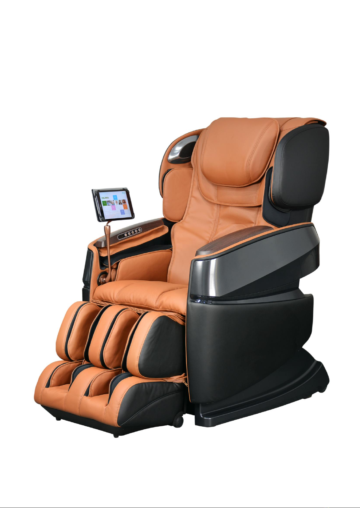
Ogawa OG8020 Manual

Maintenance Service Manual
OG8020

Catalog
1: Precautions for inspection and repair
2: OG8020 massage chair auto-check list
3: Common Troubles and Maintenance Methods list
4: Tools List
5-1: Guidance of Disassemble the backrest
5-2: Guidance of Disassemble the tablet holder
5-3: Guidance of Disassemble the side board
5-4: Guidance of disassemble the arm massage assembly and keys on side
baord
5-5: Guidance of disassemble the shoulder massage
5-6: Guidance of disassemble the backrest frame
5-7: Guidance of disassemble the backrest cable
5-8: Guidance of disassemble the massage mechanism
5-9: Guidance of disassemble the 3D PCB
5-10: Guidance of disassemble the power amplifier PCB
5-11: Guidance of disassemble the fabric & the air bag of backrest
5-12: Guidance of disassemble the PCB tray
5-13: Guidance of Disassemble the Main PCB, power PCB and blue tooth PCB
5-14: Guidance of disassemble the inflator pump box
5-15: Guidance of disassemble the thigh massage unit
5-16: Guidance of Disassemble the backrest pad

5-17: Guidance of Disassemble the seat pad
5-18: Guidance of disassemble backrest actuator
5-19: Guidance of disassemble footrest actuator
5-20: Guidance of disassemble the Z-G actuator
5-21: Guidance of disassemble the lower side board and rear roller
5-22: Guidance of disassemble the footrest and footrest PCB
5-23: Guidance of disassemble air valves inside footrest
5-24: Guidance of replace the footrest extend assembly

1. Precautions for inspection and repair
Inspection
Verify that the power cord is tightly connected on the machine.
Be careful to avoid electric shock.
Repair
Power off the supply before repair work begins.
Keep things tidy and in order during repair work.
When changing more than one part, identify the parts that are damaged and reuse
the serviceable parts.
During the dismantling or assembling process, do not damage other parts and PCB.
Be on the alert for loose or disconnected connectors during repair.
Do not leave any screws or other foreign objects in the unit after it is assembled.
Carry out test operation of the machine after the repair work is done.
It is preferable to perform the repair work on a carpet to prevent scratching or
dirtying the unit.
Clean the workplace after repair work is completed.

OG8020 Massage Chair Auto-check List
STEPS OF START Automatic detection:
Service=>Technical support=>Automatic detection
code
Phenomenon
Malfunction description
Solutions
Remarks
03
Main PCB can't
receive signals
from 3D PCB
1.Backreat cable is not
well connected.
2.Backrest cable is
broken
1.Check backrest cable
connecter. Make sure it
is perfectly
connected.
2.Change backrest
cable.
Turn on the
chair, it
will check by
itself
04
Signal from rolling
motor counting
sensor is abnormal
1. Rolling motor counting
sensor is defective.
2. Rolling motor counting
sensor is not well
connected.
3.3D PCB is defective
1. Change rolling motor
counting sensor.
2. Check whether
rolling motor counting
sensor is well
connected.
3.Change 3D PCB
Turn on the
chair, it
will check by
itself
05
Some key is keep
press for over 45
seconds
1.Some key on side board
is get stuck.
1.Change right side
board
Turn on the
chair, it
will check by
itself
06
Main PCB can't
receive signals
from footrest PCB.
1.Footrest cable is not
connect good
2.Footrest cable is
disconnected
1.Reconnect footrest
cable
2.Change footrest
cable
Turn on the
chair, it
will check by
itself
07
Signals from wideth
inspection board is
abnormal
1.Wideth inspection
board is defective
2.Wideth inspection wire
is defective or not well
connected.
3.3D PCB is defective
1.Change wideth
inspection board
2.Change wideth
inspection board wire.
3.Change 3D PCB.
when start
automatic
detection

08
Can't receive wide
signal
1.Wideth inspection
board is defective2.The
wire of wideth inspection
board is broken or not
disconnected
3.3D PCB is
defective4.Kneading
motor is dead or kneading
motor belt is loosen
1.Change wideth
inspection
board.2.Change the
wire of wideth
inspection board
3.Change 3D PCB
4.Fixing kneading belt
or change massage
mechanism
when start
automatic
detection
09
3D PCB can't
receive mid signal
1.Wideth inspection
board is defective
2.The wire of wideth
inspection board is
broken or disconnected
3.3D PCB is defective
4.Kneading motor is dead
or kneading motor belt is
loosen
1.Change wideth
inspection board.
2.Change the wire of
wideth inspection
board 3.Change
3D PCB
4.Fixing kneading belt
or change massage
mechanism
when start
automatic
detection
10
Can't receive
narrow signal
1.Wideth inspection
board is defective
2.The wire of wideth
inspection board is
broken or not well
connected
3.3D PCB is defective
4.Kneading motor is dead
or kneading motor belt is
loosen
1.Change wideth
inspection board.
2.Change the wire of
wideth inspection
board 3.Change
3D PCB
4.fixing kneading belt
when start
automatic
detection
11
Signals from wideth
inspection board is
abnormal
1.3D PCB is defective
1.Change 3D PCB
when start
automatic
detection
12
Though not turn on
kneading function,
but 3D PCB still
detect signals from
wideth inspection
board
1.3D PCB is defective.
1.Change 3D PCB
when start
automatic
detection
13
Detected signals
from up limit
sensor and down
limit sensor at
same time
1.up&down limit sensor is
defective2.The wire
which connect up & down
limit sensor to 3D PCB is
broken
3.3D PCB is defective
1.Change up&down limit
sensor2.Change the
wire which connect
up&down limit sensor
and 3D PCB.
3.Change 3D PCB
when start
automatic
detection

14
3D PCB didn't
receive signals
from up limit
sensor within 40
seconds
1.Up & down limit sensor
is defective
2.Up&Down limit sensor
wire is disconnected
3.Rolling motor is dead
or rolling motor wire is
disconnected
1.Change up&down limit
sensor
2.Check whether
up&down limit sensor
wire is connect good
3.Check whether
rolling motor wire is
connect good or change
massage mechanism
when start
automatic
detection
15
Kneading motor or
tapping motor is
overload
1.Kneading motor is
overload
2.Tapping motor is
overload
1.Change 3D PCB
When turn on
the chair.it
will check by
itself
16
Signals from
up&down limit
senaor is abnormal
1.Up & down limit sensor
is defective
1.Change up & down
limit sensor
When start
automatic
detection
17
Signals from
up&down limit
senaor is abnormal
1.Up & down limit sensor
is defective
2.Up&Down limit sensor
wire is disconnected
3.Rolling motor is dead
or rolling motor wire is
disconnected
1.Change up&down limit
sensor
2.Check whether
up&down limit sensor
wire is connect good
3.Check whether
rolling motor wire is
connect good or change
massage mechanism
when start
automatic
detection
18
Signals from
up&down limit
senaor is abnormal
1.Up & down limit sensor
is defective
1.change up & down
limit sensor
when start
automatic
detection
19
Can't detect
signals from
footrest actuator
counting sensor
1.Footrest actuaor is
defective2.Footrest
actuator motor wire is
disconnected3.Footrest
actuator counting sensor
wire is disconnected
1.Change footrest
actuator2.Check
whether footrest
actuator motor wire is
well connected3.Check
whether footrest
actuator counting
sensor wire is well
connected
when start
automatic
detection

25
Can't detect
signals from
backrest actuator
counting sensor
1.Backrest actuaor is
defective
2.Backrest actuator
motor wire is
disconnected
3.Backrest actuator
counting sensor wire is
disconnected
1.Change backrest
actuator
2.Check whether
footrest actuator
motor wire is well
connected
3.Check whether
footrest actuator
counting sensor wire is
well connected
when start
automatic
detection
26
Can't detect
signals from
backrest actuator
counting sensor
1.Z-G actuaor is
defective
2.Z-G actuator motor wire
is disconnected
3.Z-G actuator counting
sensor wire is
disconnected
1.Change Z-G actuator
2.Check whether Z-G
actuator motor wire is
well connected
3.Check whether Z-G
actuator counting
sensor wire is well
connected
when start
automatic
detection
27
3D limit sensor
signal is abnormal
1.3D limit sensor is
defective
2.The connecter of 3D
limit sensor is
disconnected
1.Change 3D limit
sensor
2.Check 3D limit sensor
connecter, make sure it
is well connected
when start
automatic
detection
28
3D limit sensor
signal is abnormal
1.3D limit sensor is
defective
2.The wire which connect
3D limit sensor and 3D PCB
is disconnected
3.3D motor is defective
or disconnected
4.Photoelectric counter
is loose
1.Change 3D limit
sensor
2.Check whether 3D
limit sensor is well
connected
3.Check whether 3D
motor is well connected
or change massage
mechanism
4.Check whether
photoelectric is loose
when start
automatic
detection
29
3D limit sensor
signal is abnormal
1.3D extend counting
sensor is defective
2.The wire which
connecting 3D counting
sensor and 3D PCB is
disconnected
1.Change 3D extend
counting sensor
2.Check whether 3D
counting sensor wire is
connect good
when start
automatic
detection

30
3D limit sensor
signal is abnormal
1.3D limit sensor is
defective
1.Change 3D limit
sensor
when start
automatic
detection
31
Footrest can't
extend or retract,
or signal from
footrest counting
sensor is abnormal
1.Footrest motor is get
stuck. 2.Footrest
counting sensor is loosen
3.Footrest counting
sensor is defective.
1.Reset the chair.
2.Change footrest
assembly
When turn on
the chair.it
will check by
itself

3: Common Troubles and Maintenance Methods are listed as following:
NO.
Phenomenon
Description
Maintenance Methods
01
No Function
When Starting.
The LCD isn’t illuminating:
①Fuse melts (in the Power Source Box or on
the transformer wire).
②Power supply circuit poorly connected.
③main PCB fails.
①Replace Fuse.
②Replace Power Box.
③Replace main PCB.
02
No function
when starting.
The LCD is illuminating:
①Mechanical switch fails or it’s wire is
opened.
②Up or Down Stroke Photo-electricity fails.
③Main PCB fails.
④Kneading is on without pressing any key
when starting and no response by pressing
other keys.
①Replace mechanical switch or it's
wire.
②Replace Stroke Photo-
electricity.
③Replace the main PCB.
④Width Inspection Board of PCB
fails, replace it.
03
No Width
switchover.
①The terminals of Width Inspection on main
PCB and wires are poorly connected.
②The terminals of Width Inspection on
massage mechanical and wires are poorly
connected.
③Width Inspection fails.
④Main PCB fails.
①&②Plug the terminal securely or
replace the wires.
③Replace Width Inspection.
④Replace the main PCB.
04
No Partial
Function.
①Height Inspection Terminal or wire poorly
contacts.
②Height Counting Subassembly fails.
①Plug the terminal securely or
replace the wires.
②Replace Height Counting Sub
-assembly.

05
No Rolling.
①Terminal or Wire Poorly Contacts.
②Down-stroke Photo-electricity
Subassembly Fails.
③Up-stroke Photo-electricity
Subassembly Fails.
④Rolling Motor Fails.
⑤Main PCB Fails.
①Plug the terminal securely or
replace the wires.
②Replace Down-Stroke Sub-
assembly.
③Replace Up-Stroke Sub-
assembly.
④Replace Rolling Motor.
⑤Replace main PCB.
06
No kneading.
①The terminals on main PCB and wires are
poorly connected.
②Kneading motor fails.
③Main PCB fails.
①Plug the terminal securely or
replace the wires.
②Replace the kneading motor.
③Replace main PCB.
07
No tapping.
①The terminals on main PCB and wires are
poorly connected.
②Tapping motor fails.
③Main PCB fails.
①Plug the terminal securely.
②Replace the tapping motor.
③Replace main PCB.
08
No response
when pressing
the keys on the
remote
controller.
①The terminals and wires are poorly
connected.
②The PCB in the remote controller fails.
①Plug the terminal securely or
replace the wires.
②Replace the remote controller.
09
Back rest
cannot be
reclined or
raised
①The terminals of reclining actuator and
wires are poorly connected.
②The reclining actuator fails.
③Main PCB fails.
①Plug the terminal securely.
②Replace reclining actuator.
③Replace main PCB.
10
Foot rest
cannot be
raised or
lowered.
①The terminals of foot rest actuator and
wires are poorly connected.
②The foot rest actuator fails.
③Main PCB fails.
①Plug the terminal securely.
②Replace foot rest actuator.
③Replace main PCB.
11
No vibration by
the motors in
the seat-pad.
①Print motors fail.
②The terminals and wires are poorly
connected or the wires fail.
③Main PCB fails.
①Replace the print motor.
②Plug the terminal securely or
replace the wires.
③Replace main PCB.

12
No gas charging
in the seat-pad.
①The terminal of the snuffle valves and
wires are poorly connected.
②The snuffle valves fail.
③The inflator pump fails.
④Main PCB fails.
①Plug the terminal securely.
②Replace the snuffle valves.
③Replace the inflator pump.
④Replace main PCB.
13
No gas charging
in the foot rest.
①The terminal of the snuffle valves and
wires are poorly connected.
②The snuffle valves fail.
③The inflator pump fails.
④Main PCB fails.
①Plug the terminal securely.
②Replace the snuffle valves.
③Replace the inflator pump.
④Replace main PCB.

5-1: Guidance of Disassemble the backrest
A: Locate the zipper between the top pillow and backrest. Unzip it to the end and remove the
pillow. (As pictures below)
B: Turn over the top pad of backrest. Locate the zipper between backrest pad and backrest.
Unzip it and detach the backrest pad from backrest. (As pictured below)
C: Locate the backrest cable connecter at rear of the chair. Slacken the two screw bolts until
you can pull them up. Then disconnect the backrest cable connector. (As pictured below)
The pillow has been
detached.
Unzip the zipper to the end.
Locate the backrest cable connecter
Two screw bolts have been pull up.
Connecter has been disconnected.
Top pad of backrest.
Unzip the zipper
Backrest pad detached
from backrest.

D: There is a hook at the bottom of the backrest. Pull the hook up meanwhile push the
backrest forward. Lay the backrest above the seat pad assy. ( As pictured below)
D: Use long nose pliers get rid of the cotter pin and the bolt. Now the backrest has been
separated from the backrest actuator. (As pictured below)
E: Locate backrest air hose connecter. Disconnect it.
G: Hold the backrest vertically and pull it up, then we can take off the backrest. ( As pictured
below)
Attention: The backrest is heavy, If possible ask somebody help you to take it off. There is
a hook at the bottom, so make sure the backrest lay on its back to prevent damage the
floor.
Pull the hook,
meanwhile push the
backrest forward
Locate the cotter pin and the bolt.

5-2: Guidance of disassemble the tablet holder
A: Take off the tablet cover first. Then remove the screw bolt which locks the tablet holder.
(As pictured below)
B: Slide the tablet holder to take it off. As pictured below.
Pull the backrest up
vertically

5-3: Guidance of disassemble the side board.
A: Locate the two zipper heads at the bottom of side board. Completely unzip the zipper.
Then lift the cover. (As pictured below)
B: Locate the two screws which lock the side board. Remove these two screws with Allen key.
(As pictured below)
3: Pull the side board up to detach from the base. Then disconnect the air hose connector and
wire connector and the side board can be removed. (As pictured below)

5-4: Guidance of disassemble arm massage assembly and the keys on side board
A: Take off the right sideboard. (Refer to 5-3: Guidance of disassemble the side board )
B: Locate zipper head of arm massage. Unzip the zipper to the end. (As pictured below)
C: Remove the four screws which secure the arm massage. Then the arm massage can be
detached. (As pictured below)
D: Locate the four screws which lock the armrest cover. Remove these four screws first. Then
lift the cover up and the armrest cover can be detached. There is one controller board and
one charging board on the inner side of right armrest cover. As pictured below.
Locate the four screws.

E: Disconnect the two connectors which connect to charging board. Remove the four screws
which lock the charging board. Then the charging board can be taken off. (As pictured
below)
F: Remove the screws which lock the control board supportor then take them off. Disconnect
the connectors which connect to control board. Remove the screws which lock control
board. Now the control board and key can be taken off. As pictured below.
G: Remove the four screws which lock the key. Then the key can be taken off. As pictured
below.
Locate the screws which secure the
control board supportor

5-5: Guidance of disassemble the shoulder massage
A: Take off the side board first. (Refer to 5-3: Guidance of disassemble the side board. )
B: Push the shoulder massage to the narrow position then release it. And the shoulder
massage will open to the wide position. (As pictured below)
C: Locate the four screws which lock the shoulder massage. Use a long screw driver to remove
the four screws. (As pictured below)
D: Detach the shoulder massage unit from the backrest. Disconnect the air hose and wire
connecter. Now the shoulder massage can be taken off. (As pictured below)
Locate the four screws
Other manuals for OG8020
2
Table of contents
Other Ogawa Massager manuals

Ogawa
Ogawa iModa PLUS User manual

Ogawa
Ogawa OG6250 User manual

Ogawa
Ogawa mobile seat NX User manual

Ogawa
Ogawa SMART RELUXE OG6383 User manual

Ogawa
Ogawa OGF 8299 User manual

Ogawa
Ogawa Master Drive User manual

Ogawa
Ogawa OG6020 User manual

Ogawa
Ogawa OG-8800 User manual

Ogawa
Ogawa mobile Shiatsu QT User manual

Ogawa
Ogawa estiloLITE PLUS User manual

Ogawa
Ogawa Acu Therapy User manual

Ogawa
Ogawa MasterDrive Duo User manual

Ogawa
Ogawa Caree Touch User manual

Ogawa
Ogawa OG-8800 User manual

Ogawa
Ogawa OG3088 User manual

Ogawa
Ogawa OG5020 User manual

Ogawa
Ogawa omknee OGCF2002A User manual

Ogawa
Ogawa BellaX User manual

Ogawa
Ogawa SMART VOGUE PLUS User manual

Ogawa
Ogawa OG7500 User manual