Oki C7500n User manual

Oki Data CONFIDENTIAL
Name
C7550/C7350,C7500/C7300
Color LED Page Printer
Maintenance Manual
[041124A]
No.01
41955801TH
C7550/C7350,C7500/C7300 (ODA/OEL/INT)
Maintenance Manual
1
174
2004-04-23
Akio Kikuchi Tomoyo Sugiyama
41955801TL C7550/C7350,C7500/C7300 Disassembly for Maintenance
41955801TR C7550/C7350,C7500/C7300 RSPL
Yoshinori Fujisawa
7 2004-04-23 HP9-0004 Change format Tomoyo Sugiyama Akio Kikuchi
8 2004-09-08 SE2-0248 Add to C7550/C7350 Takayuki Oshima Hiroshi Ueno

41955801TH Rev.8 2 /
Oki Data CONFIDENTIAL
1
2002-10-23
2 2002-11-29 NP11 Haruyama
3 2003-06-06 7 158 Part No. of the Control Panel Bezel ME4 Ueda
4 2003-07-14 Add CU(VE Version) CN11 Yamanaka
5 2003-12-19 Add PU(VE Version) NP32 Ishizuka
6 2004-01-26 21,159 Partial change CN11 Yamanaka
7 2004-03-05 Partial change NP32 Ishizuka
8 2004-09-08 Add to C7550/C7350 NP51 Oshima
Rev.No. Date No.
Corrected items
Page Description of change
Person in
change
Document Revision History

41955801TH Rev.8 3 /
Oki Data CONFIDENTIAL
PREFACE
This manual describes the procedures of the maintenance of the C7550/C7350,C7500/C7300 of printers.
The document is produced for maintenance personnel use. For details on the procedures for handling the
C7550/C7350,C7500/C7300 of printers, see its user documentation.
Note!
• The descriptions in this manual are subject to change without prior notice.
• In preparing the document, efforts have been made to ensure that the information in it is accurate.
However, errors may be crept into the document. Oki Data assumes no responsibility for any
damage resulting from, or claimed to be the results of, those repairs, adjustments or modifica-
tions to the printers which are made by users using the manual.
• The parts used for the printers are sensitive and, if handled improperly, may be damaged. It is
strongly recommended that the products are maintained by maintenance men registered with
Oki Data.
•Oki Data strongly recommends that you do NOT connect our LED page printers to an
uninterruptiblePower Supply (UPS). For further information, please contact Oki Data directly at
800-OKIDATA or www.okidata.com.

41955801TH Rev.8 4 /
Oki Data CONFIDENTIAL
CONTENTS
1. CONFIGURATIONS ......................................................................................... 7
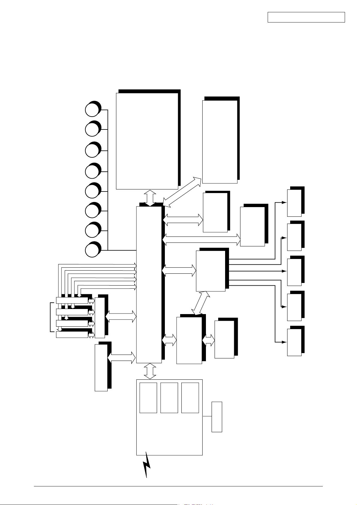
1.1 System Configuration....................................................................................................... 7
1.2 Printer Configuration ........................................................................................................8
1.3 Option Configuration ........................................................................................................ 9
1.4 Specifications ................................................................................................................. 10
2. PARTS REPLACEMENT ................................................................................ 12
2.1 Precautions in Replacing Parts ...................................................................................... 12
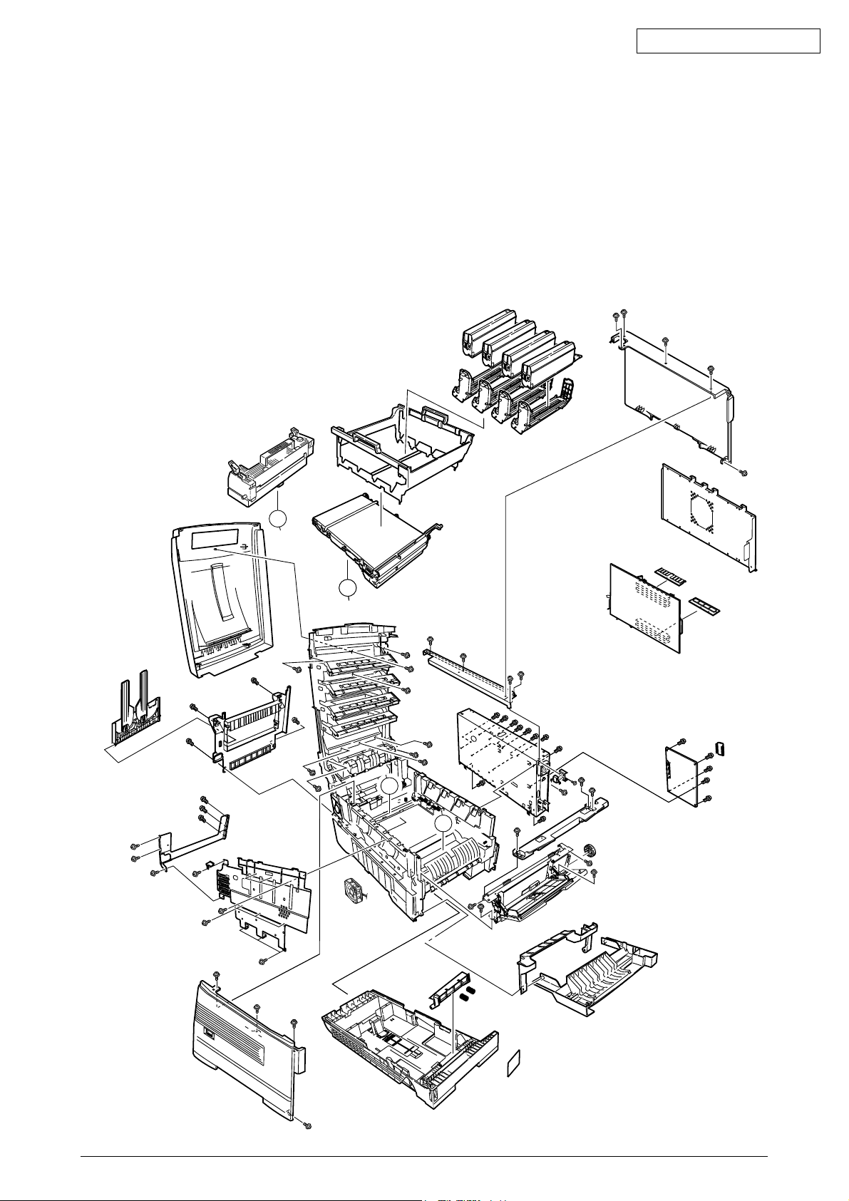
2.2 Parts layout .................................................................................................................... 14
2.3 Replacing Parts..............................................................................................................20
2.3.1 Top Cover ......................................................................................................... 22
2.3.2 LED Head / LED Spring / Post-Guide............................................................... 23
2.3.3 Top Cover Unit ................................................................................................. 24
2.3.4 Control Panel Assy/ Control Panel Bezel/ LED Control PWB/ Toner Sensors/
Stacker Full Sensor/ Control Panel/ Control Panel Tape Harness/ Eject Rollers . 25
2.3.5 Top Cover Handle/ Top Cover Latch/ Top Cover Latch Spring ........................ 26
2.3.6 Eject Guide Assy .............................................................................................. 27
2.3.7 Cassette Assy/ Front Cover Assy/ Front Cover Inner Baffle ........................... 28
2.3.8 Retard Pad Assy/ Retard Pad Assy Spring ...................................................... 29
2.3.9 Feed Roller and Nudger Roller ......................................................................... 30
2.3.10 Rear Cover ....................................................................................................... 31
2.3.11 Face-Up Tray.................................................................................................... 32
2.3.12 Left Side Cover ................................................................................................. 33
2.3.13 Right Side Cover .............................................................................................. 34
2.3.14 Multipurpose Tray Assy/ Multipurpose Tray Cover Assy/ Links/
Multipurpose Tray Top Cover/ Multipurpose Tray Drive Gear .......................... 35
2.3.15 Drum Contact Assys ......................................................................................... 36
2.3.16 Media Thickness Sensor Assy......................................................................... 37
2.3.17 Registration Roller Assy (A)/ Registration Drive Gear (A) ................................ 38
2.3.18 Registration Roller Assy (B) ............................................................................. 39
2.3.19 Registration Clutch and Registration Motor Assy ............................................. 40
2.3.20 Main Cooling Fan ............................................................................................. 41
2.3.21 Color Registration Sensor Assy........................................................................ 42
2.3.22 Duplex Guide Assy ........................................................................................... 43
2.3.23 Electrical Chassis Cooling Fan ......................................................................... 44
2.3.24 Printer Engine Controller PWB ......................................................................... 45
2.3.25 Printer Unit Chassis .......................................................................................... 46
2.3.26 Entrance Cassette Sensor Actuator ................................................................. 47
2.3.27 Entrance Sensor PWB...................................................................................... 48
2.3.28 Entrance MT Sensor Actuator / Entrance Belt Sensor Actuator /
Entrance Waste Chassis Sensor Actuator ...................................................... 49
2.3.29 Fuser Exit Roller ............................................................................................... 50
2.3.30 Exit Sensor Assy .............................................................................................. 51
2.3.31 Fuser Latching Handle (L) ................................................................................ 52
2.3.32 Belt Motor Assy ................................................................................................ 53
2.3.33 Fuser Latching Handle (R) ............................................................................... 54
2.3.34 Main Motor Assy ............................................................................................... 55
2.3.35 Main Feeder Drive Motor .................................................................................. 56
2.3.36 Contact Assy/ Left Plate Assy .......................................................................... 57
2.3.37 Low Voltage Power Supply............................................................................... 58
2.3.38 High voltage power supply ............................................................................... 59
2.3.39 Main Feed Assy ................................................................................................ 60
2.3.40 Cassette/ Left Guide Assy ................................................................................ 61
2.3.41 Cassette/ Right Guide Assy.............................................................................. 62
2.3.42 Fuser Unit ......................................................................................................... 63
2.3.43 Belt Unit ............................................................................................................ 64

41955801TH Rev.8 5 /
Oki Data CONFIDENTIAL
2.3.44 Duplex Unit ....................................................................................................... 65
2.3.45 Guide Rails (L) and (R)..................................................................................... 66
2.3.46 Duplex Transport Assembly ............................................................................. 67
2.3.47 CU Assy............................................................................................................ 69
3. Adjustment .................................................................................................... 72
3.0 System Maintenance MENU .......................................................................................... 72
3.0.1 ID Check Pattern Printing ( " TEST PRINT MENU " item )............................... 73
.......................................................................................................................... 73
3.1 Maintenance Mode and Functions ................................................................................. 73
3.1.1 Maintenance menu ........................................................................................... 73
3.1.2 Engine maintenance mode ............................................................................... 75
3.1.2.1 Operator panel .................................................................................. 75
3.1.2.2 Normal self-diagnostic mode (Level 1).............................................. 75
3.1.2.2.1 Entering self-diagnostic mode (Level 1) ............................ 76
3.1.2.2.2 Exiting the self-diagnostic mode ....................................... 76
3.1.2.3 Switch scan test ................................................................................ 76
3.1.2.4 Motor clutch test ................................................................................ 80
3.1.2.5 Test print ........................................................................................... 82
3.1.2.6 Initializing NVM ................................................................................. 86
3.1.2.7 Displaying the consumables counter ................................................ 87
3.1.2.8 Displaying the consumables continuation counter ............................ 87
3.1.2.9 Panel display details ......................................................................... 88
3.1.3 Various print jobs with single printer unit attached with a controller ................. 93
3.2 Adjustment After Replacing Parts .................................................................................. 94
3.2.1 Precautions in replacing the engine control board ........................................... 94
3.2.2 Precautions in replacing EEPROM................................................................... 94
3.2.3 Replacing EEPROM after replacing the CU board ........................................... 95
3.2.4 Destination Setting (Checking Metod: Printing Demo Page) ............................ 95
3.2.5 Recovery Flash ROM data on CU board .......................................................... 96
3.2.6 Notes on replacing Oki LAN8100e or CU boards equipped with Oki LAN8100e96
3.3 Adjusting the Density ..................................................................................................... 96
3.4 Paper Thickness Detection Sensitivity Adjustment and Media Thickness Detection
Value Check................................................................................................................... 97
3.4.1 Applicable Operating Systems and Interfaces, and File Required ................... 97
3.4.2 Setting .............................................................................................................. 98
3.4.2.1 Menu Setting ..................................................................................... 98
3.4.2.2 Media Setting .................................................................................. 100
3.4.2.3 Sensitivity Adjustment ..................................................................... 101
3.4.2.4 Actions for NG Sensitivity Adjustment............................................. 102
3.4.3 Inputting the density of the calibration chip for density detection ................... 103
3.4.3.1 Density Adjustment Menu Setting ................................................... 103
3.4.4 Electronic Serial Number Input ....................................................................... 105
4. regular maintenance ................................................................................... 106
4.1 Parts Replaced Regularly ............................................................................................ 106
4.2 Cleaning ....................................................................................................................... 106
4.3 Cleaning the LED Lens Array ...................................................................................... 106
4.4 Cleaning the Pick-up Roller ......................................................................................... 106
5. Troubleshooting Procedures ..................................................................... 107
5.1 Precautions before troubleshooting ............................................................................. 107
5.2 Precautions before handling an abnormal image ........................................................ 107
5.3 Precautions upon handling an abnormal image........................................................... 107
5.4 Preparing for Troubleshooting ..................................................................................... 108

41955801TH Rev.8 6 /
Oki Data CONFIDENTIAL
5.5 Troubleshooting Procedure.......................................................................................... 108
5.5.1 LCD message list ........................................................................................... 109
5.5.2 Preparing for troubleshooting ......................................................................... 115
5.5.3 Troubleshooting for abnormal images ............................................................ 126
5.6 Fuse check................................................................................................................... 141
5.7 Life Counter Tool ......................................................................................................... 141
6. CONNECTION DIAGRAM ............................................................................ 142
6.1 Resistance Checks ...................................................................................................... 142
6.2 Program/Font ROM Layouts ........................................................................................ 146
APPENDIX A INTERFACE SPECIFICATIONS ................................................. 154
1. Parallel Interface Specifications ................................................................................... 154
1.1 Parallel Interface............................................................................................. 154
1.2 Parallel Interface Connector and Cable.......................................................... 154
1.3 Parallel Interface Level ................................................................................... 154
1.4 Timing Charts ................................................................................................. 155
1.5 Parallel I/F Signals.......................................................................................... 156
2. Universal Serial Bus (USB) Interface Specifications.................................................... 157
2.1 USB Interface ................................................................................................. 157
2.2 USB Interface Connector and Cable .............................................................. 157
2.3 USB Interface Signals .................................................................................... 157
APPENDIX B 2ND/3RD TRAY MAINTENANCE .............................................. 158
1. Parts Replacement ...................................................................................................... 158
1.1 Cover Idle Roller Assy .................................................................................... 158
1.2 PCB ................................................................................................................ 159
1.3 Feeder Drive Assy .......................................................................................... 160
APPENDIX C C7100/7300/7350/9300/9500 SERIES ERROR MESSAGES .... 161
1. C7100/7300/7350/9300/9500 Series (Error messages) .............................................. 161
2. C7100/7300/7350/9300/9500 Series
(Error messages : Related to Color, Media Detect) ...
168
3. C7100/7300/7350/9300/9500 Series
(Warning messages : Related to usage, media) .......
171
4. C7100/7300/7350/9300/9500 Series (Warning messages : Job Account) .................. 172
5. C7100/7300/7350/9300/9500 Series (Other Warning) ................................................ 173

41955801TH Rev.8 7 /
Oki Data CONFIDENTIAL
MM M MMMMM
LED Head
Centronics I/F
USB I/F
2 × Option Slots
Junction Board
Pulse Motor
Engine Control
Low Voltage
Power Unit
Fuser
Unit
High Voltage
Power Unit 2nd/3rd Tray
Duplex
Unit
Belt
Unit
<Sensors, Switches and Thermistors>
Paper size sensor (4 bits)
Paper empty sensor
Paper near empty sensor
MT paper empty sensor
FF home switch
Loading sensor 1
Loading sensor 2
C-ID
Unit
M-ID
Unit
Y-ID
Unit
K-ID
Unit
C ID M ID Y ID K IDBelt Heat
MT/
Registration Hopping
Operator Panel
2 × ROM
DIMMs
3 × RAM
DIMM
IDE
I/F(HDD)
DC Fan
Note
Note Option Slot: LAN Card
< advanced Sensors,>
Media Thickness Detection
Density Detection
Color Misalignment Detectin
1. CONFIGURATIONS
1.1 System Configuration
Figure 1-1 shows the system configuration of the C7550/C7350,C7500/C7300 of printers.
Figure 1-1

41955801TH Rev.8 8 /
Oki Data CONFIDENTIAL
1.2 Printer Configuration
The inside of the printers is composed of the followings:
• Electrophotographic Processor
• Paper Paths
• Controller Block (CU and PU)
• Operator Panel
• Power Units (High Voltage Unit and Low Voltage Unit)
Figure 1-2 shows the printer configuration.
Figure 1-2
A
A
B
B
A
A
B

41955801TH Rev.8 9 /
Oki Data CONFIDENTIAL
1.3 Option Configuration
The followings are available as options on the C7550/C7350,C7500/C7300 of printers.
(1) 2nd Tray/ 3rd Tray
(2) Duplex Unit
(3) Expansion Memory 64/128/256/512 MB
(4) Internal Hard Disk
(5) Ethernet Board
Note: Don’t use one for
C9200/C9400
Note: Don’t use one for
C9200/C9400
Note: Don’t use one for
C9200/C9400
Note: Don’t use one for
C9200/C9400
Note: Don’t use one for
C9200/C9400

41955801TH Rev.8 10 /
Oki Data CONFIDENTIAL
1.4 Specifications
(1) External Dimensions Height: 430mm Width: 430mm Length: 620mm
(2) Weight 42 kg
(3) Papers Type: Ordinarypaper, Transparencies(Recommended:MLOHP01)
Size: Postal card, Legal 13" or 14", Executive, A4, A5, B5, A6 (Only
the 1st tray and the front feeder support A6 and postal-card
sizes.)
Weight: 1st tray55 kg to 151 kg (64 to 176g/m2)
Front feeder 55 kg to 172 kg (64 to 203g/ m2)
(4) Print Speed C7500/C7300
Color:20 pages per minute (Transparency: 8 pages per minute)
Monochrome: 24 pages per minute (Transparency: 12 pages per minute)
Postal Card, Label, Thick Paper: 12 pages per minute
C7550/C7350
Color:24 pages per minute (Transparency: 8 pages per minute)
Monochrome: 26 pages per minute (Transparency: 12 pages per minute)
Postal Card, Label, Thick Paper: 12 pages per minute
(5) Resolution 600 ×600 dots per inch (C7550/C7350)
1200 ×1200 dots per inch (C7550/C7350)
(6) Power Input 115 - 127 V , 220 - 240 V
(7) Power Consumption Peak: 1500W Normal Operation: 500W (5% duty)
Idle: 150W Power Saving Mode: 45W or less
(8) Frequency 50Hz or 60Hz ±2Hz
(9) Noise Operation: 56 dB (Without second tray)
Standby: 45 dB
Power Saving: 43 dB
(10) Consumable Life Toner Cartridge: 5,000 pages (5% duty) (each of Y, M, C and K)
Large-Capacity Toner Cartridge: 10,000 pages (5% duty)
(each of Y, M, C and K)
Image Drum: 30,000 pages (5% duty, Continuous printing)
(each of Y, M, C and K)
(11) Parts Replaced Periodically Fuser Unit Assy: Every 60,000 pages
Belt Cassette Assy: Equivalent of60,000pages (3 pages/job)

41955801TH Rev.8 11 /
Oki Data CONFIDENTIAL
(12) Temperatures and Relative Humidities
Temperature
Temperature Condition
Temperature( F) Temperature( C) Remark
Operation 50 to 89.6 10 to 32 17 to 27 C
(Temperatures to assure full
color print quality)
Non-Operation 32 to 109.4 0 to 43 Power-off
Storage (Max. One Year) -14 to 109.4 -10 to 43 With drum and toner
Transport (Max. One Month) -20 to 122 -29 to 50 With drum and without toner
Transport (Max. One Month) -20 to 122 -29 to 50 With drum and toner
Humidity
Humidity Condition
Relative Humidity Max. Wet-Bulb Remark
(%) Temperature( C)
Operation 20 to 80 25 50 to 70% (Humidities to assure full
color print quality)
Non-Operation 10 to 90 26.8 Power-off
Storage 10 to 90 35
Transport 10 to 90 40
(13) Printer Life 600,000 pages (on a A4-size basis) or five years

41955801TH Rev.8 12 /
Oki Data CONFIDENTIAL
(2) Do not disassemble the printer so long as it operates properly.
(3) Minimize the disassembly. Do not detach parts other than those shown in the replacing procedure.
(4) For maintenance, use designated tools.
(5) Follow the order instructed to disassemble the printer. Incorrect order may damage the parts.
(6) Small parts such as screws and collars tend to get lost, so temporarily place and fix them in
their original positions.
(7) When handling ICs and circuit boards such as microprocessors, ROMs and RAMs, do not use
gloves that likely to have static.
(8) Do not place the printed circuit boards directly on the printer or the floor.
2. PARTS REPLACEMENT
This section describes the procedure for replacing the parts, assemblies and units in the field. The
replacing procedure is given for detachment. To attach, use the reverse procedure.
2.1 Precautions in Replacing Parts
(1) Before replacing the parts, be sure to remove the AC cable and the interface cable.
(a) To remove the AC cable, always use the following procedure.
i) Flip the power switch of the printer off (to “O”).
ii) Pull the AC inlet plug of the AC cable out of the AC receptable.
iii) Remove the AC cable and the interface cable from the printer.
(b) To connect the printer again, always use the following procedure.
i) Connect the AC cable and the interface cable to the printer.
ii) Insert the AC inlet plug into the AC receptacle.
iii) Flip the power switch of the printer on (to “I”).
Disconnect
Connect

41955801TH Rev.8 13 /
Oki Data CONFIDENTIAL
[Maintenance Tools]
Table 2-1 lists tools necessary to replace the printed circuit boards and the units.
Table 2-1 Maintenance Tools
No.
No. 1-100 Philips
screwdriver
Q' ty Place of use RemarksService Tools
1
2
3
4
5
6
8
No. 2-200 Philips
screwdriver, Magnetized
No. 3-100 screwdriver
No. 5-200 screwdriver
Digital multimeter
Pliers
Handy cleaner
LED Head cleaner
P/N 4PB4083-2248P001
High voltage probe
1
1
1
1
1
1
1
2~2.5 mm screws
3~5 mm screws
Cleans LED head
9 1
7 1
Transparency sheet
( thickness premeasured)
42404301
Stage height adjustment jig
42423701
-
Microdriver
2.0mm
Adjustment for Media
Thickness sensor
Adjustment for Media
Thickness sensor
Adjustment for Lever
adjust
(Media Thickness)
10
11
12
1
1
1
Label

41955801TH Rev.8 14 /
Oki Data CONFIDENTIAL
2.2 Parts layout
Figure 2-1
A
A
B
B
A
A
B

41955801TH Rev.8 15 /
Oki Data CONFIDENTIAL
[Top Cover Assy]
Figure 2-2
For 1200dpi
For 600dpi

41955801TH Rev.8 16 /
Oki Data CONFIDENTIAL
[Printer Unit-1/2]
Figure 2-3
A
A

41955801TH Rev.8 17 /
Oki Data CONFIDENTIAL
[Printer Unit-2/2]
Figure 2-4

41955801TH Rev.8 18 /
Oki Data CONFIDENTIAL
[Cassette Guide Assy (L),(R)]
Figure 2-5
A
B
B
A
CC’
C
C’

41955801TH Rev.8 19 /
Oki Data CONFIDENTIAL
[Duplex Unit]
A
B
D
C
A
B
C
D
E
E
F
G
G
F
Figure 2-6

41955801TH Rev.8 20 /
Oki Data CONFIDENTIAL
2.3 Replacing Parts
This section describes how to replace the parts and assemblies shown in the following disassem-
bling system diagram.
C7550 /C7350,
C7500 /C7300 Print Engine Controller PWB (2.3.24)
x 4
LED Assy (2.3.2)
Low Voltage Power Supply (2.3.37)
High Voltage Power Supply (2.3.38)
41128101
Insurator
42153101
Main Cooling Fan Assy (2.3.20)
2381023P0003
HV Tape Harness
41940201
Printer Unit
41940001
Printer NIP
- PX711
41275901PA
Microswitch-Assy (2.3.41)
40839001
Left Cassette Guide Assy (2.3.40)
40839406
Right Cassette Guide Assy (2.3.41)
40839802
Main Feed Assy (2.3.39)
40371302
Feed Roller (2.3.9)
40325401
Main Feeder Drive Gear (2.3.39)
40313202
Nudger Roller (2.3.9)
4PP4122-1217P001
Plastic Slide (2.3.40)
40349102
Cassette Guide Pivot (R) (2.3.40)
40349701
Plastic Roller (2.3.40)
40928101
Cassette Spring (2.3.40)
4PP4076-5359P001
Cassette Lock (2.3.40)
4PP4043-4526P001
Cassette Lock Spring (2.3.40)
4PB4016-1960P002
x
2
Foot (2.3.40)
4PP4122-1217P001
Plastic Slide (2.3.41)
40349101
Cassette Guide Pivot (L) (2.3.41)
40349701
Plastic Roller (2.3.41)
40928101
Cassette Spring (2.3.41)
4PP4076-5359P001
Cassette Lock (2.3.41)
4PP4043-4526P001
Cassette Lock Spring (2.3.41)
4PB4016-1960P002
x
2
Foot (2.3.41)
40368304
Paper Size Sensing PWB PXC (2.3.41)
4PP4076-5360P001
Paper Size Actuator (2.3.41)
41143701
Duplex Assy Ground contact (2.3.41)
41309106
2nd Tray Connector (2.3.41)
41285701PA
Plate Assy-SW(Front) (2.3.41)
40844306
Regist Roller Assy (A) (2.3.17)
40848801
Transport (Transfer) Belt Motor Assy (2.3.32)
40850201
Contact Assy (2.3.36)
41303606
Left Plate Assy (2.3.36)
40864301
Rear Cover (2.3.10)
40864411
Left Side Cover (2.3.12)
40864503
Right Side Cover (2.3.13)
40864601
Front Cover Assy (2.3.7)
41042501
Front Cover Inner Baffle (2.3.7)
41374902
Face Up Tray (2.3.11)
40864901
Frame Assy - Release
40841401
Fuser Latching Handle (R) (2.3.33)
40841501
Fuser Latching Handle Spring (2.3.33)
A
40841301
Fuser Latching Handle (L) (2.3.31)
40841501
Fuser Latching Handle Spring (2.3.31)
40841601
Entrance Sensor Actuator #1 (2.3.26)
40841701
Entrance Sensor Actuator #2 (2.3.28)
40841801
Entrance Senspr Actuator #3 (2.3.28)
42199601
Waste Toner Sensor Actuator (2.3.28)
41253602
Duplex Gate solenoid Assy (2.3.29)
41968701
Registration Shutter Solenoid Assy
41944201
Registration Shutter
41968501
Registration Shutter Spring
42170801
Fuser Drive Gear-C (2.3.29)
40323902
Fuser Exit Roller (2.3.29)
40316301
Fuser Drive Gear-B (2.3.29)
4PP4076-3949P001
Fuser Exit Roller Bushing (L) (2.3.29)
4PP4043-4489P001
Fuser Exit Roller Bushing (R) (2.3.29)
41189701 x 4
Drum Contact Assy (2.3.15)
41258301
Entrance Sensor PWB (2.3.27)
41312801
Left Top Cover Spring Assy (2.3.25)
41312901
Right Top Cover Spring Assy (2.3.25)
41944001
Color Registration Sensor Assy (2.3.21)
41073601
Exit Sensor Assy (2.3.30)
41940301
Printer Chassis (2.3.25)
40844307
Regist Roller Assy (B) (2.3.18)
40845801
Registration Motor Assy (2.3.19)
41187102
Registration Clutch (2.3.19)
40859201
Duplex Guide Assy (2.3.22)
40848501
Main Feeder Drive Gear A (2.3.35)
40848601
Main Feeder Drive Gear B (2.3.35)
40846001
Main Feeder Motor (2.3.35)
40847306
Main Motor Assy (2.3.34)
This manual suits for next models
4
Table of contents
Other Oki Printer manuals

Oki
Oki B4200 User manual

Oki
Oki 10i User manual

Oki
Oki ML520n Quick start guide

Oki
Oki C5500n Series User manual

Oki
Oki ES2232a4 User manual

Oki
Oki B4200 Firmware update

Oki
Oki ES2426dn User manual

Oki
Oki MC160N Installation and maintenance instructions

Oki
Oki IP-7900-21 User manual

Oki
Oki C5800Ldn Series User manual