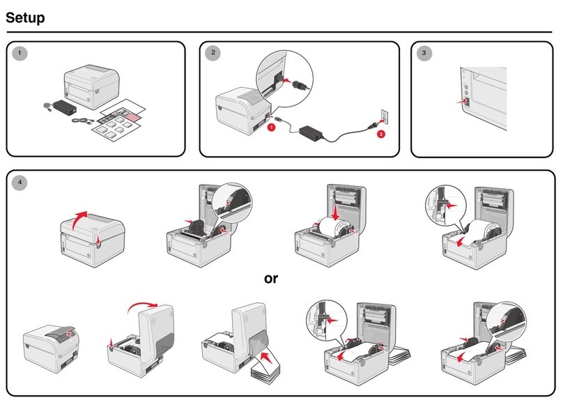
Oki T400 User manual


FCC WARNING
You are cautioned that changes or modifications not expressly approved by the
party responsible for compliance could void your authority to operate the
equipment.
This device complies with Part 15 of the FCC Rules. Operation is subject to the
following two conditions: (1) this device may not cause harmful interference,
and (2) this device must accept any interference received, including
interference that may cause undesired operation.
This equipment has been tested and found to comply with the limits for a Class
B digital device, pursuant to Part 15 of the FCC Rules. These limits are
designed to provide reasonable protection against harmful interference in a
residential installation. This equipment generates, uses and can radiate radio
frequency energy and, if not installed and used in accordance with the
instructions, may cause harmful interference to radio communications.
However, there is no guarantee that interference will not occur in a particular
installation.
If this equipment does cause harmful interference to radio or television
reception, which can be determined by turning the equipment off and on, the
user is encouraged to try to correct the interference by one or more of the
following measures:
- Reorient or relocate the receiving antenna.
- Increase the separation between the equipment and receiver.
- Connect the equipment into an outlet on a circuit different from that to which
the receiver is connected.
- Consult the dealer or an experienced radio/TV technician for help.
AC power cord with ferrite core must be used for RF interference suppression.
◆Contents ◆
Name of Parts ............................... 2
Power .............................................. 6
Computer Connection................... 8
Paper Setting................................. 9
Ribbon Setting ..........………….. 11
Does not print correctly .............. 13
When error light is ON ............... 14
Failure? ....................................... 15

Name of Parts
■Front View
Top cover
Paper check
window
Operation switch
Power switch
Front cover
■Top cover .................... Open this cover when you set the paper.
■Power switch ..............Press this switch to turn ON/OFF the printer.
■Paper check window...To check the status of paper.
■Front cover.................Open this cover to refill or set DIP-SW.
■Operation switch
• POWER ....When you turn on the power, the green light lights up. Refer to
“Starting/Power”.
• ERROR .....When an error occurs, the red light turns ON. Refer to
“When error light is ON”.
• ONLINE ...When the green light is ON, the printer can receive data. When
the light is OFF, the printer cannot receive.
• [ONLINE] button ... Press this button to stop receiving data. Resume by
pressing this button again. If this button is pressed
while printing, the printing is suspended. To resume
printing, press this button again.
• [FEED] button ........When you press this button in the offline state, you
can feed paper. If you turn on the power of the printer
while you keep pressing this button, you can print out
the printer status.
2

Back View
Fanfold paper set in place
I/F Cover
Optional interface
Connecter
Power
Connector
■Power Connector...Connects AC adapter.
■Optional interface Connecter...Connects computer.
■Fanfold Paper set in place ...
Open this to use fanfold paper.To open the folder,
remove the Top Cover and release.
■I/F Cover... It removes by exchange of an I/F board.
※
Handling of an I/F Cover:
Please close with an I/F Cover after shutting off a power supply and
attaching or removing an I/F board, in case an I/F Cover is opened.
3

■Top Cover Open
Thermal head
Driver for darkness
adjustment
Paper holder
Head
Sensor
Paper holder
slide lever
Platen roller
Head Open/Close lever
■Paper holder ... When you use a roll paper, set the paper here.You can
adjust the width according to the paper size.
■Paper holder slide lever.. Press this lever to adjust the paper holder width.
■Head ................ Open this part to refill paper.
■Head Open/Close lever .. Press this to open the head.
■Thermal head .... This is the printing area. Please keep this part clean.
■Platen roller ...... This is the part that feeds paper. Please keep this part
clean.
■Sensor ................ Paper travels over this.
■Driver for darkness adjustment ... This is used to change the print darkness.
4

■Front Cover Open
Error number display
Print darkness
adjustment volume
Sensor level DIP-SW
■Print darkness adjustment volume ..You can finely adjust the darkness that
is set in the Printer Setting screen. See
the manual for details.
■Sensor level...... Do not use this. Only for used by service personnel.
■DIP-SW............ Appropriate settings are set according to your printer
system environment.You can change the settings. See the
manual for details.
■Error number display.. When the error light is ON, check the displayed
number. This number represents the reason of the
error. See the manual for details.
5

Power
Cable Connection
1 Connect the power cable with the
main unit and AC adapter as shown
in the figure. When you insert the
AC adapter in the main unit, set the
stopper firmly.
2 Plug in the power cable to the outlet.
3 Use a Two-prong adapter if only a
two-prong outlet is available.
1 Connect the power cable with the
main unit and AC adapter as shown
in the figure. When you insert the
AC adapter in the main unit, set the
stopper firmly.
2 Plug in the power cable to the outlet.
3 Use a Two-prong adapter if only a
two-prong outlet is available.
1 Connect the power cable with the
main unit and AC adapter as shown
in the figure. When you insert the
AC adapter in the main unit, set the
stopper firmly.
2 Plug in the power cable to the outlet.
3 Use a Two-prong adapter if only a
two-prong outlet is available.
Stopper
Always make sure to ground the power cable to the ground connector,
otherwise electric shock may result. Construct the ground facility if it
is not available.
6

Power Switch
Power Switch
Press the power switch at the front side of the main unit in the “|” direction.
* When you turn on the power, the POWER light lights up. Please confirm
this.
When you turn off the printer, flip the switch to the “ ” direction.
7

Computer Connection
Connection example using Bi-directional parallel interface
Use [Bi-directional parallel interface(sold separately)].
This printer operates by being connected to a computer.
Turnoff the power of the printer and connect to the computer with an
interface cable connecting the bi-directional parallel interface connector at
the rear panel of the printer.
* If you are using a different optional interface board, refer to the instructions of
its “Optional Interface”.
8

Paper Setting
1 Confirm the [PUSH] mark on the
Left/Right side of the main unit.
While depressing the mark on the cover, open
the Top cover
2 Press the Head Open/Close lever to
the direction as shown in Figure.
Confirm that the head is detached from the
platen roller part, then lift the head in the
direction as shown in the Figure.
3 While pressing the paper holder slide
lever, adjust the paper holder to the paper
size.
4 Set the paper on the paper holder.
9

5 Pull the paper,then pass under the sensor.
6 Close the head to the home position.
7 Depress the [PUSH] mark with finger
until fixed firmly.
Close the Top cover.
8 Set the top of the paper by pressing the
[FEED] button.
Finally, press the [ONLINE] button to change
the online status.
10

Ribbon Setting
Thermal Transfer model OKI POS T400/T410 only.
1 Confirm the [PUSH] mark on the Left/Right
side of the main unit.
While depressing the mark on the cover, open
the Top cover.
2 Press the Head Open/Close lever to the
direction as shown in Figure.
Confirm that the head is detached from the
platen roller part, then lift the head in the
direction as shown in the Figure.
3 While pressing the Ribbon Core Lock
button, pull the ribbon core from the unit.
* The roller is also opened.
4 Insert the ribbon core in the ribbon supply
spindle on the opposite side.
And insert the empty ribbon core to the
ribbon rewind spindle on this side.
Please confirm the direction of the roll.
Insert the guide part of the ribbon core in the
slot of the ribbon unit side and return the
ribbon core to the unit.
11

5 Please insert the ribbon core and fix
firmly.
* There are three depths according
to the ribbon width.
*Insert in the specified position by
pressing the Lock button.
6 Pull out the ribbon along with the
head. Stick the edge of the ribbon
into the empty ribbon core by using
a tape.
Rotate the Ribbon Roll-up Knob
in the clockwise direction and the
wind up the ribbon several times.
7 Close the roller to the home position.
Close the head to the home position.
8 Depress the [Push] mark with finger
until fixed firmly. Close the Top
cover.
*When replace the ribbon the next time, keep
the ribbon core and replace the used ribbon
with new ribbon.
12

Does not print correctly
Print error
• Paper set correctly?
➞
Please set the paper correctly.
• Platen roller clean?
➞
If the platen roller is not clean, clean it using the Cleaning Kit
(refer to the manual).
• Paper replenished regularly?
➞
If the edge of the paper does not set regularly, the paper cannot
be fed to the printer correctly. Please be sure to use paper.
• Is the data or signal from the computer is correct?
➞
Please turn off and on the power of the printer. Confirm the
contents and communication conditions of the software in your
computer.
• Setting of paper position correction adjusted?
➞
Please correct the position. See the manual for details.
• Label adhered the sensor?
➞
Remove the label and clean up.
• Sensor clean?
➞
Clean the sensor.
Paper is fed but does not print
• Thermal head clean? No label is adhered to the head?
➞
If the thermal head is not clean, clean the head using the Cleaning
Kit.
➞
If a label is adhered to the thermal head, remove the label.
Please make sure not to remove the label using metal instruments such
as a screw driver. It may damage the thermal head.
➞
If the stick from the label is adhered to the thermal head, clean
it using the Cleaning Kit.
Printout is not clear
• Print darkness appropriate?
➞
You can adjust the print darkness (refer to the manual).
➞
You can adjust the Print Darkness Adjustment Volume (refer to
the manual) by changing the printer darkness settings in the Printer
Setting screen. When you use the Print Darkness Adjustment Volume, be
sure to read the manual.
13

• Paper set correctly?
➞
Please confirm that the paper is set correctly.
• Platen roller clean?
➞
If the platen roller is not clean, clean the platen roller using the
Cleaning Kit (refer to the manual).
• Thermal head clean? No label is adhered to the head?
➞
If the thermal head is not clean, clean the head using the
Cleaning Kit.
➞
If a label is adhered to the thermal head, remove the label.
Please make sure not to remove the label using metal instruments such
as a screw driver. It may damage the thermal head.
➞
If the stick from the label is adhered to the thermal head,
clean it by using the Cleaning Kit.
• Paper clean?
➞
Please use a clean paper.
When error light is ON
Error light
[ERROR] light
Error Number Display
When the error light is ON or flashing, there is an error.
Confirm the error number that is shown on the Error Number Display. This
number indicates the reason of the error.
See the manual for details.
14

Failure?
Please confirm the following before you decide it’s a mechanical failure.
POWER light is not ON even if you turn on the machine.
AC adapter and power cable are plugged in the outlet correctly?
➞
Plug in AC adapter and power cable into the outlet correctly.
AC adapter is plugged in to the main unit correctly?
➞
Plug in the AC adapter to the main unit power connector firmly.
No damages of the power cable?
➞
Replace the power cable. A new power cable is available in
your local dealer.
➞
Please do not use other power cables.
Is there any electricity come from the outlet?
➞
Confirm the power source of the outlet.
If there is no problem with the power source, confirm that electricity is
supplied to your building.
Please also check for any power cut possibility.
Fuse or breaker is not functioning?
➞
If so replace the fuse and turn on the breaker.
AC adapter light is ON?
➞
If it is not ON, confirm the power source.
15

AVERTISSEMENT DE LA FCC
Les changements ou modifications qui ne sont expressément approuvés par la partie
responsable d’assurer la conformité pourraient résilier votre droit d’utiliser
l’équipement.
Ce dispositif est conforme à la partie 15 de la réglementation FCC. Le
fonctionnement est soumis aux deux conditions suivantes : 1) cet appareil ne doit pas
provoquer d’interférences néfastes, et 2) cet appareil doit tolérer les interférences
reçues, y compris celles qui risquent de provoquer un fonctionnement indésirable.
À l’issue des tests dont il a fait l’objet, cet appareil a été déclaré conforme aux normes
des appareils numériques de classe B conformément à la partie 15 de la
réglementation FCC. Ces normes sont destinées à assurer un niveau de protection
adéquat contre les interférences dans les installations résidentielles. Cet appareil
produit, utilise et peut émettre des fréquences radioélectriques et, sil n’est pas installé
ou utilisé conformément aux directives, peut brouiller les ondes radio. Toutefois, il est
impossible de garantir qu’aucune interférence ne se produira dans une installation
particulière.
Si cet appareil brouille la réception des ondes radio et télévision, ce que vous pouvez
déterminer en éteignant et en rallumant l’appareil, nous vous encourageons à prendre
l’une ou plusieurs des mesures correctives suivantes :
–Réorientez ou déplacez l’antenne.
–Éloignez l’appareil du récepteur.
–Branchez l’appareil à une autre prise ou sur un autre circuit que celui du récepteur.
–Demandez conseil au revendeur de l’appareil ou à un technicien radio/télévision
expérimenté.
Le cordon d’alimentation CA doit être utilisé pour la suppression des interférences
RF.

Contenu
Noms des pièces .............................. 2
Alimentation..................................... 6
Connexion ordinateur....................... 8
Réglage papier.................................. 9
Réglage du ruban............................11
Impression incorrecte ....................13
Témoin d’erreur allumé .................14
Panne? . ..........................................15
Other manuals for T400
4
This manual suits for next models
1
Table of contents
Languages:
Other Oki Printer manuals
Popular Printer manuals by other brands

Samsung
Samsung ML-4500/XAA Service manual

Ricoh
Ricoh Aficio BP20N Administrator's guide

Avery Dennison
Avery Dennison Monarch 9825 quick reference

Epson
Epson 1400 - Stylus Photo Color Inkjet Printer Start here

Olivetti
Olivetti d-Copia 600 Service manual

Lexmark
Lexmark E460DN - Taa Govt Compliant printing guide