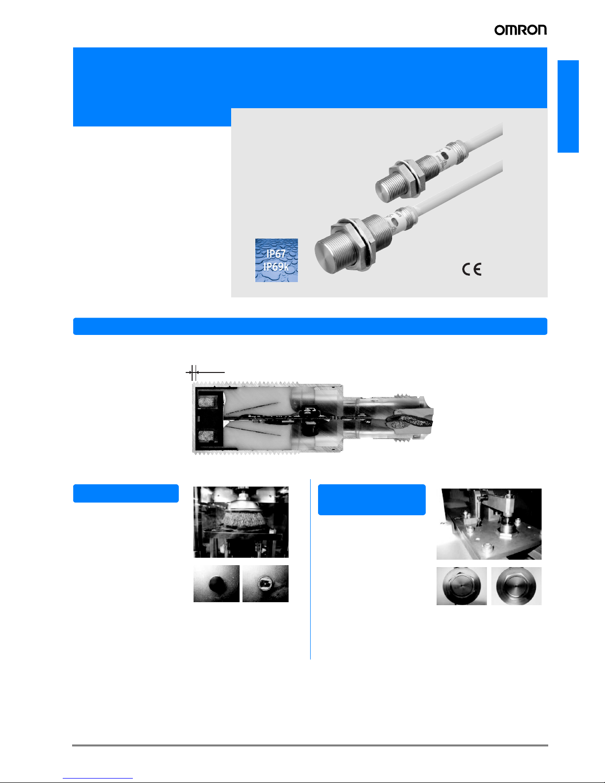
Omron E2FM - User manual

E2FM
A-1E2FM
Inductive Proximity Sensor in full metal housing
E2FM
• Full body stainless steel housing for
highest mechanical protection
• Low frequency modulation for metal
chip immunity
• Flame retardant cable for high protec-
tion against welding spatter damage
Application
Full body stainless steel housing with 0.8 mm thick sensing face protection
0.8 mm
The stainless-steel
head shows minimal
wear when cleaned
with a metal brush.
More than 20 times
the durability of
standard sensors.
Brush Test
E2FM Standard sensor
Continuous Impact
Test
Standard sensor E2FM
The standard sensor
with top wall thickness
of 0.2 mm was pene-
trated after
10,000 impacts.
The E2FM was
not penetrated
after 250,000
impacts (depth:
0.26 mm).

A-2 Inductive Proximity Sensor
Features
Ordering Information
Sensors
DC 2-Wire, Pre-wired Connector Models
DC 3-Wire, M12 Connector Models
Tested resistance against:
• Sodium chloride
• Gasoline
• Dilute sodium hydroxide
• Dilute hydrochloric acid
• Mineral oil
• Barium hydroxide
...for metal chip immunity reducing false signals
caused by spatter accumulation and small metal
objects.
Appearance Sensing distance Output configuration Operation mode Model
Shielded
M8 Polarity: Yes,
Pin allocations: 1-4
NO
E2FM-X1R5D1-M1GJ
M12
Polarity: Yes,
Pin allocations: 1-4 E2FM-X2D1-M1GJ
No polarity: No,
Pin allocations: 3-4 E2FM-X2D1-M1GJ-T
M18
Polarity: Yes,
Pin allocations: 1-4 E2FM-X5D1-M1GJ
No polarity: No,
Pin allocations: 3-4 E2FM-X5D1-M1GJ-T
M30
Polarity: Yes,
Pin allocations: 1-4 E2FM-X10D1-M1GJ
No polarity: No,
Pin allocations: 3-4 E2FM-X10D1-M1GJ-T
Appearance Sensing distance Output configuration Operation mode Model
Shielded M8
DC 3-Wire, PNP NO
E2FM-X1R5B1-M1
M12 E2FM-X2B1-M1
M18 E2FM-X5B1-M1
M30 E2FM-X10B1-M1
Chemical and Oil Resistance (examples) Low frequency modulation...
Flush mounting installation possible
conventional
products
E2FM
Not influenced by
surrounding
installation
environment.
Note: When mounted in steel.
Minimum
installation
distance
Workpiece
Workpiece
1.5 mm
2 mm
5 mm
10 mm
1.5 mm
2 mm
5 mm
10 mm

A-3E2FM
E2FM
Rating and Specifications
DC 2-Wire (E2FM-X@D@)
* The response frequency of the DC switching section is an average value. Measurement conditions are as follows: standard sensing object, a distance of twice the
standard sensing object, and a set distance of half the sensing distance.
Size M8 M12 M18 M30 M12 M18 M30
Shielded Shielded
Item Model E2FM-X1R5D1
-M1GJ
E2FM-X2D1
-M1GJ
E2FM-X5D1
-M1GJ
E2FM-X10D1
-M1GJ
E2FM-X2D1
-M1GJ-T
E2FM-X5D1
-M1GJ-T
E2FM-X10D1
-M1GJ-T
Sensing distance 1.5 mm±10% 2 mm±10% 5 mm±10% 10 mm±10% 2 mm±10% 5 mm±10% 10 mm±10%
Set distance 0 to 1.05 mm 0 to 1.4 mm 0 to 3.5 mm 0 to 7 mm 0 to 1.4 mm 0 to 3.5 mm 0 to 7 mm
Differential travel 15% max. of sensing distance
Sensing object Ferrous metal (The sensing distance decreases with non-ferrous metal. Refer to Engineering Data on page 5.)
Standard sensing
object
Iron,
8 ×8 ×1 mm
Iron,
12 ×12 ×1
mm
Iron,
30 ×30 ×1
mm
Iron,
54 ×54 ×1
mm
Iron,
12 ×12 ×1
mm
Iron,
30 ×30 ×1
mm
Iron,
54 ×54 ×1
mm
Response frequency * 200 Hz 100 Hz 100 Hz 50 Hz 100 Hz 100 Hz 50 Hz
Power supply voltage
(operating voltage
range)
12 to 24 VDC (10 to 30 VDC), ripple (p-p): 10% max.
Leakage current 0.8 mA max.
Output configuration With polarity Without polarity
Control
output
Switching
capacity 3 to 100 mA
Residual
voltage
3 V max.
(Load current: 100 mA, Cable length: 2 m)
5 V max.
(Load current: 100 mA, Cable length: 2 m)
Indicators Operation indicator (red LED), Setting/Operation indicator (green LED)
Operation mode
(with sensing object
approaching)
NO
Protection circuits Surge suppressor, Load short-circuit protection
Ambient temperature
range Operating/Storage: -25 to 70°C (with no icing or condensation)
Ambient humidity
range Operating/Storage: 35% to 95% (with no condensation)
Temperature
influence ±20% max. of sensing distance at 23°C in the temperature range of -25 to 70°C.
Voltage influence ±1% max. of sensing distance at rated voltage in the rated voltage ±15% range
Insulation resistance 50 MΩmin. (at 500 VDC) between current-carrying parts and case
Dielectric strength 1,000 VAC, 50/60 Hz for 1 minute between current carry parts and case
Vibration resistance Destruction: 10 to 55 Hz, 1.5 mm double amplitude for 2 hours each in X, Y, and Z directions
Shock resistance
Destruction:
500 m/s2
10 times each
in X, Y, and Z
directions
Destruction: 1,000 m/s210 times each in X, Y, and Z directions
Degree of protection IEC 60529 IP67, DIN 40050 part 9: IP69k
Connection method Pig-tail Connector Models (Standard cable length: 0.3 m)
Weight (packed state) Approx. 65 g Approx. 85 g Approx. 110 g Approx. 190 g Approx. 85 g Approx. 110 g Approx. 190 g
Materi-
als
Case Stainless steel (SUS303)
Sensing
surface Stainless steel (SUS303)
(thickness) (0.4 mm) (0.8 mm) (0.8 mm)
Clamping
nuts Stainless steel (SUS303)
Cable PVC (flame retardant)
Toothed
washer Zinc-plated iron
Accessories Instruction manual

A-4 Inductive Proximity Sensor
DC 3-Wire (E2FM-X@B@)
* The response frequency of the DC switching section is an average value. Measurement conditions are as follows: standard sensing object, a distance of twice the
standard sensing object, and a set distance of half the sensing distance.
Size M8 M12 M18 M30
Shielded Shielded
Item Model E2FM-X1R5B1-M1 E2FM-X2B1-M1 E2FM-X5B1-M1 E2FM-X10B1-M1
Sensing distance 1.5 mm±10% 2 mm±10% 5 mm±10% 10 mm±10%
Set distance 0 to 1.05 mm 0 to 1.4 mm 0 to 3.5 mm 0 to 7 mm
Differential travel 15% max. of sensing distance
Sensing object Ferrous metal (The sensing distance decreases with non-ferrous metal. Refer to Engineering Data on page 5.)
Standard sensing
object Iron, 8 ×8 ×1 mm Iron, 12 ×12 ×1 mm Iron, 30 ×30 ×1 mm Iron, 54 ×54 ×1 mm
Response frequency * 200 Hz 100 Hz 100 Hz 50 Hz
Power supply voltage
(operating voltage
range)
12 to 24 VDC (10 to 30 VDC), ripple (p-p): 10% max.
Current consumption 10 mA max.
Output configuration PNP open collector output
Control
output
Switching
capacity 200 mA max.
Residual
voltage 2 V max. (Load current: 200 mA, Cable length: 2 m)
Indicators Operation indicator (yellow LED)
Operation mode
(with sensing object
approaching)
NO
Protection circuits Reversed power supply polarity protection, Surge suppressor, Load short-circuit protection, and Reversed out-
put polarity protection (except the E2FM-X1R5B1-M1)
Ambient temperature
range Operating/Storage: -25 to 70°C (with no icing or condensation)
Ambient humidity
range Operating/Storage: 35% to 95% (with no condensation)
Temperature
influence ±20% max. of sensing distance at 23°C in the temperature range of -25 to 70°C.
Voltage influence ±1% max. of sensing distance in the rated voltage ±15% range (using the sensing distance at the rated voltage
as standard)
Insulation resistance 50 MΩmin. (at 500 VDC) between current-carrying parts and case
Dielectric strength 1,000 VAC, 50/60 Hz for 1 minute between current carry parts and case
Vibration resistance Destruction: 10 to 55 Hz, 1.5-mm double amplitude for 2 hours each in X, Y, and Z directions
Shock resistance
Destruction: 500 m/s2
10 times each in X, Y, and
Z directions
Destruction: 1,000 m/s210 times each in X, Y, and Z directions
Degree of protection IEC 60529 IP67, DIN 40050 part 9: IP69k
Connection method Connector Models
Weight (packed state) Approx. 45 g Approx. 55 g Approx. 75 g Approx. 160 g
Materi-
als
Case Stainless steel (SUS303)
Sensing
surface Stainless steel (SUS303)
(thickness) (0.4mm) (0.8mm)
Clamping
nuts Stainless steel (SUS303)
Toothed
washer Zinc-plated iron
Accessories Instruction manual

A-5E2FM
E2FM
Engineering Data (Typical)
Sensing Area Influence of Sensing Object Size and Material
E2FM-X@E2FM-X1R5@E2FM-X2@
Leakage Current
E2FM-X5@E2FM-X10@E2FM-X@D1-M1GJ(-T)
Residual Output Voltage
E2FM-X@B1-M1 E2FM-X@D1-M1GJ(-T)
E2FM-X2D@
E2FM-X10@
E2FM-X1R5@
12
10
8
6
4
2
0
E2FM-X5@
Distance X (mm)
-25 -15-20 -10 -5 0 5 10 15 20 25
Distance Y (mm)
2.5
2.0
1.5
1.0
0.5
0.0
0 5 10 15 20 25
Distance X (mm)
Stainless
steel
(SUS304)
Aluminum
Brass
Copper
Iron
Side length of sensing object: d (mm)
3.0
2.5
2.0
1.5
1.0
0.5
0.0
01015202530355
Distance X (mm)
Iron
Aluminum
Brass
Copper
Stainless
steel
(SUS304)
Side length of sensing object: d (mm)
7
6
5
4
3
2
1
0
020406080
Distance X (mm)
Stainless
steel
(SUS304)
Iron
Brass
Aluminum
Copper
Side length of sensing object: d (mm)
12
10
8
6
4
2
0
0 102030405060 809070
Distance X (mm)
Side length of sensing object: d (mm)
Stainless
steel
(SUS304)
Iron
Brass
Aluminum
Copper
E2FM-X1R5D1-M1GJ
1.0
0.8
0.6
0.4
0.2
0.0
0 5 10 15 20 25 30
Leakage current (mA)
Power supply voltage (V)
E2FM-X5D1-M1GJ(-T)
E2FM-X2D1-M1GJ(-T)
E2FM-X10D1-M1GJ(-T)
2
1.5
1
0.5
0
1 10 50 100 200 1,000
E2FM-X1R5B1-M1
E2FM-X2B1-M1
E2FM-X5B1-M1
E2FM-X10B1-M1
Residual output voltage (V)
Load current (mA)
5
4
3
2
1
0
1 3 5 1 0 3 0 5 0 100
E2FM-X@D1-M1GJ
Residual output voltage (V)
Load current (mA)
E2FM-X@D1-M1GJ-T

A-6 Inductive Proximity Sensor
I/O Circuit Diagrams
DC 2-Wire Models
DC 3-Wire Models
Operation
mode Model Timing chart Output circuit
NO
E2FM-
X@D1-
M1GJ
E2FM-
X@D1-
M1GJ-T
Opera-
tion
mode
Output
configu-
ration
Model Timing chart Output circuit
NO
PNP
open-
collector
model
E2FM-
X1R5B1-
M1
E2FM-
X2B1-M1
E2FM-
X5B1-M1
E2FM-
X10B1-M1
100 0
Non-sensing area
Sensing object
Unstable
sensing
area
Set position
Stable sensing
area
Proximity sensor
Rated
sensing
distance
ON
ON
OFF
OFF
ON
OFF
Setting
indicator
(green)
Operation
indicator
(red)
Control
output
(%) 70 (TYP)
0 V
1
4
Proximity
sensor
main
circuit
Note: The load can be connected to either the +V or 0 V side.
Load
12 to 24 VDC
Connector Pin
Arrangement
Note: Pins 2 and 3
are not used.
4
3
Proximity
sensor
main
circuit
12 to 24 VDC
Load
Connector Pin
Arrangement
Note: Pins 1 and 2
are not used.
0 V (12 to 24 VDC)
Note 1. The load can be connected to either the +V or 0 V side.
2. The E2FM-X@@1-M1GJ-T has no polarity. There is no need to be concerned
about the polarity of pins 3 and 4.
100 0
Non-sensing area Sensing area
Sensing object
Rated
sensing
distance
Proximity sensor
ON
OFF
ON
OFF
Operation
indicator
(yellow)
Control
output
(%)
0 V
1
4
3
Proximity
sensor
main
circuit
12 to 24 VDC
Load
Connector Pin
Arrangement
Note: Pin 2 is not used.
Note: There is no reversed output polarity protection diode.
0 V
1
4
3
Proximity
sensor
main
circuit
Load
Connector Pin
Arrangement
Note: Pin 2 is not used.
12 to 24 VDC

A-7E2FM
E2FM
Safety Precautions
This product is not designed or rated for ensuring
safety of persons. Do not use it for such purposes.
Never use this product with an AC power supply.
Otherwise, explosion may result.
The following precautions must be observed to ensure safe
operation.
1. Do not use the Sensor in an environment where
inflammable or explosive gas is present.
2. Do not attempt to disassemble, repair, or modify any
Sensors.
3. Power Supply Voltage
Do not use a voltage that exceeds the rated operating
voltage range. Applying a voltage that is higher than the
operating voltage range may result in explosion or fire.
4. Incorrect Wiring
Be sure that the power supply polarity and other wiring is
correct. Incorrect wiring may cause explosion or fire.
5. Connection without a Load
If the power supply is connected directly without a load, the
internal elements may explode or burn. Be sure to insert a
load when connecting the power supply.
Do not use the Sensor under ambient conditions that exceed
the ratings to ensure maximum lifetime:
1. Please do not use the Sensor in the following locations.
(1) Outdoor locations directly subject to sunlight, rain, snow, or
water droplets
(2) Locations subject to atmospheres with chemical vapors, in
particular solvents and acids
(3) Locations subject to corrosive gas
2. The Sensor may malfunction if used near ultrasonic cleaning
equipment, high-frequency equipment, transceivers, cellular
phones, inverters, or other devices that generate a high-frequency
electric field. Refer to the Sensor General Catalog for typical
measures.
3. Laying the Sensor wiring in the same conduit or duct as high-
voltage wires or power lines may result in incorrect operation and
damage due to induction. Wire the Sensor using a separate
conduit or independent conduit.
4. Cleaning
Never use thinner or other solvents. Otherwise, the Sensor surface
may be dissolved.
Design
Influence of Surrounding Metal
When the Proximity Sensor is embedded in metal, make sure
that the clearances given in the following table are main-
tained. The values depend on the type of nuts used for mount-
ing. Be sure to use the supplied nuts (SUS303).
(Unit: mm)
Note: The influence from other non-magnetic surrounding metals is nearly the
same as that from aluminum.
Mutual Interference
When installing two or more Sensors face-to-face or side-by-
side, ensure that the minimum distances given in the following
table are maintained.
Chips from Cutting Aluminum or Cast Iron
Normally, chips from cutting aluminum or cast iron will not
cause a detection signal to be output even if it adheres to or
accumulates on the detection surface. In the following cases,
however, a detection signal may be output. Remove the cut-
ting chips in these cases.
Mounting
Do not tighten the nut with excessive force. A washer must be
used with the nut. Do not use tightening force that exceeds the
values in the following table.
WARNING
Precautions for Safe Use
Precautions for Correct Use
l
D
d dia.
l
m
n
Item
l d D m n
Model Embedding
material
E2FM-X1R5@
Iron 0 8 0 4.5 30
Aluminum 10 50 10 4.5 50
E2FM-X2@
Iron 0120 840
Aluminum 16 70 16 8 70
E2FM-X5@
Iron 0 18 0 20 60
Aluminum 16 80 16 20 80
E2FM-X10@
Iron 0 30 0 40 100
Aluminum 24 120 24 40 120
A
B
(U
n
i
t: mm
)
Model Item A B
E2FM-X1R5@35 30
E2FM-X2@40 35
E2FM-X5@65 60
E2FM-X10@110 100
1. If d ≥D at the center of the
detection surface where d is the
cutting chip size and D is the
detection surface size
Model Dimension
(mm) D
E2FM-X1R5@6
E2FM-X2@10
E2FM-X5@16
E2FM-X10@28
2
3d
DDetection surface
Cutting chip
Cutting chips
Pressed down
Model Torque
E2FM-X1R5@9 N·m
E2FM-X2@30 N·m
E2FM-X5@70 N·m
E2FM-X10@180 N·m

A-8 Inductive Proximity Sensor
Dimensions (Unit: mm)
Sensors Pig-tail Connector Models
M12 Connector Models
Toothed washer
*1
25
49
M8 ×1
M12 ×1
13
45
30
15 dia.
Two clamping
nuts Indicator *2
*1. 4-dia. vinyl-insulated round cable (flame retardant), Standard length; 300 mm
*2. Operation indicator (red/green)
Setting indicator (green)
E2FM-X1R5D1-M1GJ
17
47
33
53
39
21 dia.
Two
clamping nuts
Toothed washer
Indicator *2
*1. 6-dia. vinyl-insulated round cable (flame retardant), Standard length; 300 mm
*2. Operation indicator (red/green)
Setting indicator (green)
M12 ×1
*1
M12 ×1
E2FM-X2D1-M1GJ
E2FM-X2D1-M1GJ-T
24
36
42
56
410
M18 ×1
29dia.
Two clamping
nuts
Toothed washer
Indicator *2 *1
M12 ×1
*1. 6-dia. vinyl-insulated round cable (flame retardant), Standard length; 300 mm
*2. Operation indicator (red/green)
Setting indicator (green)
E2FM-X5D1-M1GJ
E2FM-X5D1-M1GJ-T
36
63.5
49
43
510
M30 ×1.5
42 dia.
Toothed washer
Two clamping
nuts Indicator *2
*1
M12 ×1
*1. 6-dia. vinyl-insulated round cable (flame retardant), Standard length; 300 mm
*2. Operation indicator (red/green)
Setting indicator (green)
E2FM-X10D1-M1GJ
E2FM-X10D1-M1GJ-T
45
13
25
30
34.5
53.5
15 dia.
Two
clamping
nuts
Toothed washer
Four operation indicators (yellow)
M12 ×1
M8 ×1
E2FM-X1R5B1-M1
17
53
39
33
47
21 dia.
Two clamping
nuts
Toothed washer
M12 ×1
Four operation indicators (yellow)
M12 ×1
E2FM-X2B1-M1
24
10
56
42
36
4
29dia.
M18 ×1
Two clamping
nuts
Toothed washer
M12 ×1
Four operation indicators (yellow)
E2FM-X5B1-M1
63.5
49
43
510
36
42 dia.
Two clamping
nuts
Toothed washer
Four operation indicators (yellow)
M30 ×1.5
M12 ×1
E2FM-X10B1-M1
F
Mounting Hole Dimensions
Dimension M8 M12 M18 M30
F (mm) 8.5 dia. 12.5 dia. 18.5 dia. 30.5 dia.
+0.5
0
+0.5
0
+0.5
0
+0.5
0

A-9E2FM
E2FM
READ AND UNDERSTAND THIS DOCUMENT
Please read and understand this document before using the
products. Please consult your OMRON representative if you have
any questions or comments.
WARRANTY
OMRON’s exclusive warranty is that the products are free from
defects in materials and workmanship for a period of one year (or
other period if specified) from date of sale by OMRON.
OMRON MAKES NO WARRANTY OR REPRESENTATION,
EXPRESS OR IMPLIED, REGARDING NON-INFRINGEMENT,
MERCHANTABILITY, OR FITNESS FOR PARTICULAR PURPOSE
OF THE PRODUCTS. ANY BUYER OR USER ACKNOWLEDGES
THAT THE BUYER OR USER ALONE HAS DETERMINED THAT
THE PRODUCTS WILL SUITABLY MEET THE REQUIREMENTS
OF THEIR INTENDED USE. OMRON DISCLAIMS ALL OTHER
WARRANTIES, EXPRESS OR IMPLIED.
LIMITATIONS OF LIABILITY
OMRON SHALL NOT BE RESPONSIBLE FOR SPECIAL,
INDIRECT, OR CONSEQUENTIAL DAMAGES, LOSS OF PROFITS
OR COMMERCIAL LOSS IN ANY WAY CONNECTED WITH THE
PRODUCTS, WHETHER SUCH CLAIM IS BASED ON CONTRACT,
WARRANTY, NEGLIGENCE, OR STRICT LIABILITY.
In no event shall responsibility of OMRON for any act exceed the
individual price of the product on which liability is asserted.
IN NO EVENT SHALL OMRON BE RESPONSIBLE FOR
WARRANTY, REPAIR, OR OTHER CLAIMS REGARDING THE
PRODUCTS UNLESS OMRON’S ANALYSIS CONFIRMS THAT
THE PRODUCTS WERE PROPERLY HANDLED, STORED,
INSTALLED, AND MAINTAINED AND NOT SUBJECT TO
CONTAMINATION, ABUSE, MISUSE, OR INAPPROPRIATE
MODIFICATION OR REPAIR.
SUITABILITY FOR USE
THE PRODUCTS CONTAINED IN THIS DOCUMENT ARE NOT
SAFETY RATED. THEY ARE NOT DESIGNED OR RATED FOR
ENSURING SAFETY OF PERSONS, AND SHOULD NOT BE
RELIED UPON AS A SAFETY COMPONENT OR PROTECTIVE
DEVICE FOR SUCH PURPOSES. Please refer to separate catalogs
for OMRON's safety rated products.
OMRON shall not be responsible for conformity with any standards,
codes, or regulations that apply to the combination of products in the
customer’s application or use of the product.
At the customer’s request, OMRON will provide applicable third party
certification documents identifying ratings and limitations of use that
apply to the products. This information by itself is not sufficient for a
complete determination of the suitability of the products in
combination with the end product, machine, system, or other
application or use.
The following are some examples of applications for which particular
attention must be given. This is not intended to be an exhaustive list
of all possible uses of the products, nor is it intended to imply that the
uses listed may be suitable for the products:
• Outdoor use, uses involving potential chemical contamination or
electrical interference, or conditions or uses not described in this
document.
• Nuclear energy control systems, combustion systems, railroad
systems, aviation systems, medical equipment, amusement
machines, vehicles, safety equipment, and installations subject to
separate industry or government regulations.
• Systems, machines, and equipment that could present a risk to life
or property.
Please know and observe all prohibitions of use applicable to the
products.
NEVER USE THE PRODUCTS FOR AN APPLICATION INVOLVING
SERIOUS RISK TO LIFE OR PROPERTY WITHOUT ENSURING
THAT THE SYSTEM AS A WHOLE HAS BEEN DESIGNED TO
ADDRESS THE RISKS, AND THAT THE OMRON PRODUCT IS
PROPERLY RATED AND INSTALLED FOR THE INTENDED USE
WITHIN THE OVERALL EQUIPMENT OR SYSTEM.
PERFORMANCE DATA
Performance data given in this document is provided as a guide for
the user in determining suitability and does not constitute a warranty.
It may represent the result of OMRON’s test conditions, and the
users must correlate it to actual application requirements. Actual
performance is subject to the OMRON Warranty and Limitations of
Liability.
CHANGE IN SPECIFICATIONS
Product specifications and accessories may be changed at any time
based on improvements and other reasons.
It is our practice to change model numbers when published ratings or
features are changed, or when significant construction changes are
made. However, some specifications of the product may be changed
without any notice. When in doubt, special model numbers may be
assigned to fix or establish key specifications for your application on
your request. Please consult with your OMRON representative at any
time to confirm actual specifications of purchased products.
DIMENSIONS AND WEIGHTS
Dimensions and weights are nominal and are not to be used for
manufacturing purposes, even when tolerances are shown.
ERRORS AND OMISSIONS
The information in this document has been carefully checked and is
believed to be accurate; however, no responsibility is assumed for
clerical, typographical, or proofreading errors, or omissions.
PROGRAMMABLE PRODUCTS
OMRON shall not be responsible for the user’s programming of a
programmable product, or any consequence thereof.
COPYRIGHT AND COPY PERMISSION
This document shall not be copied for sales or promotions without
permission.
This document is protected by copyright and is intended solely for
use in conjunction with the product. Please notify us before copying
or reproducing this document in any manner, for any other purpose.
If copying or transmitting this document to another, please copy or
transmit it in its entirety.

A-10 Inductive Proximity Sensor
In the interest of product improvement, specifications are subject to change without notice.Cat. No. D104-E2-01-X
OMRON EUROPE B.V.
Wegalaan 67-69,
NL-2132 JD, Hoofddorp,
The Netherlands
Phone: +31 23 568 13 00
Fax: +31 23 568 13 88
www.eu.omron.com
Table of contents
Other Omron Accessories manuals

Omron
Omron Sti F3SJ-AM P Series Operating and maintenance instructions

Omron
Omron E3NT-L User manual

Omron
Omron E3Z series User manual

Omron
Omron ZS Operating manual

Omron
Omron E3X-N User manual

Omron
Omron FQ-BAT1 User manual

Omron
Omron E3X-DAC-S Series User manual

Omron
Omron ZFV-LTF01 User manual

Omron
Omron E3Z-LT User manual

Omron
Omron E4PA-N User manual

Omron
Omron ZS-HLDS60 User manual

Omron
Omron E3AS-HL150 Series User manual

Omron
Omron F160 Vision Sensor User manual

Omron
Omron E3C-LDA - 3 User manual

Omron
Omron ZFX-SC50S User manual

Omron
Omron FZ Series User manual

Omron
Omron E3T - User manual

Omron
Omron ZS-HLDS32 User manual

Omron
Omron E39 Series User manual

Omron
Omron FHV7H-C004-H19-MC User guide