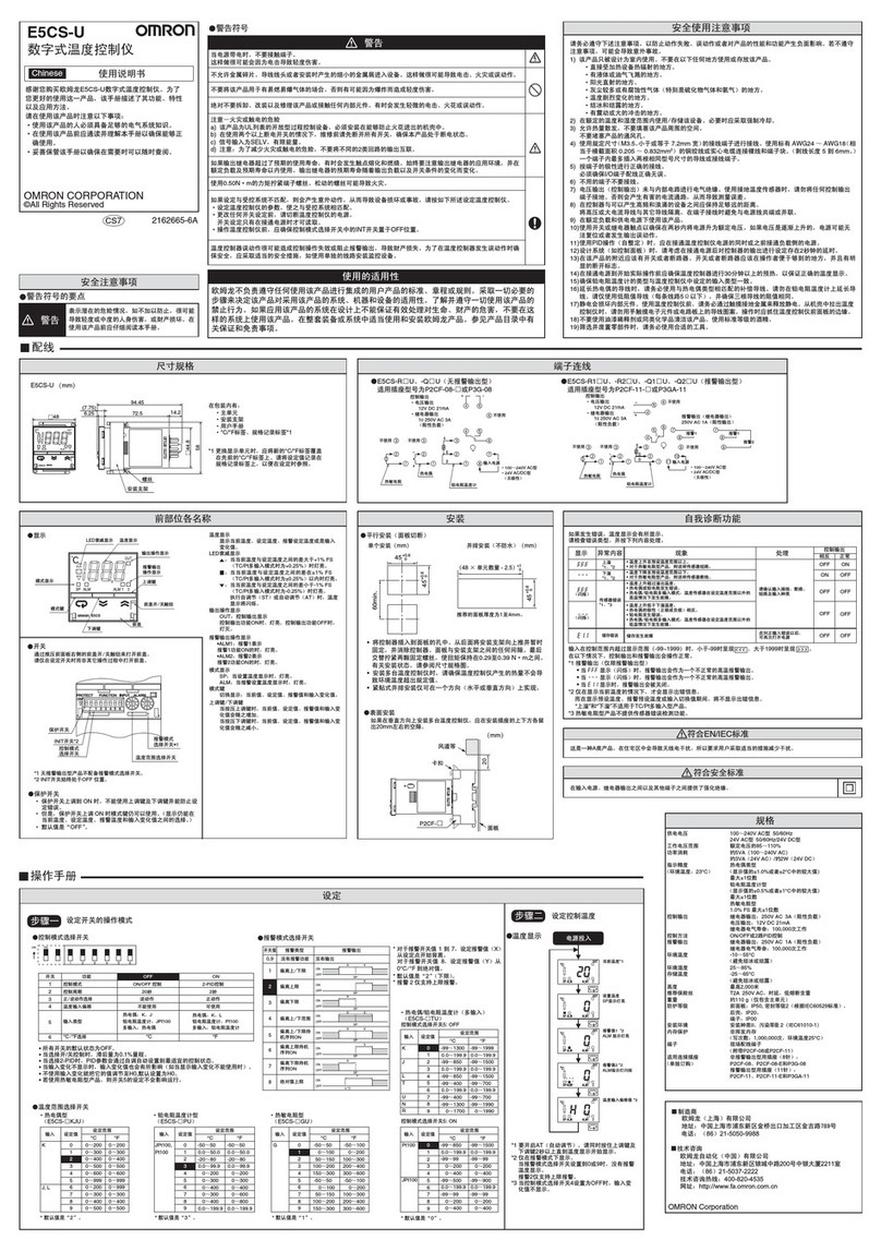
Lock
Slider
Cover seal
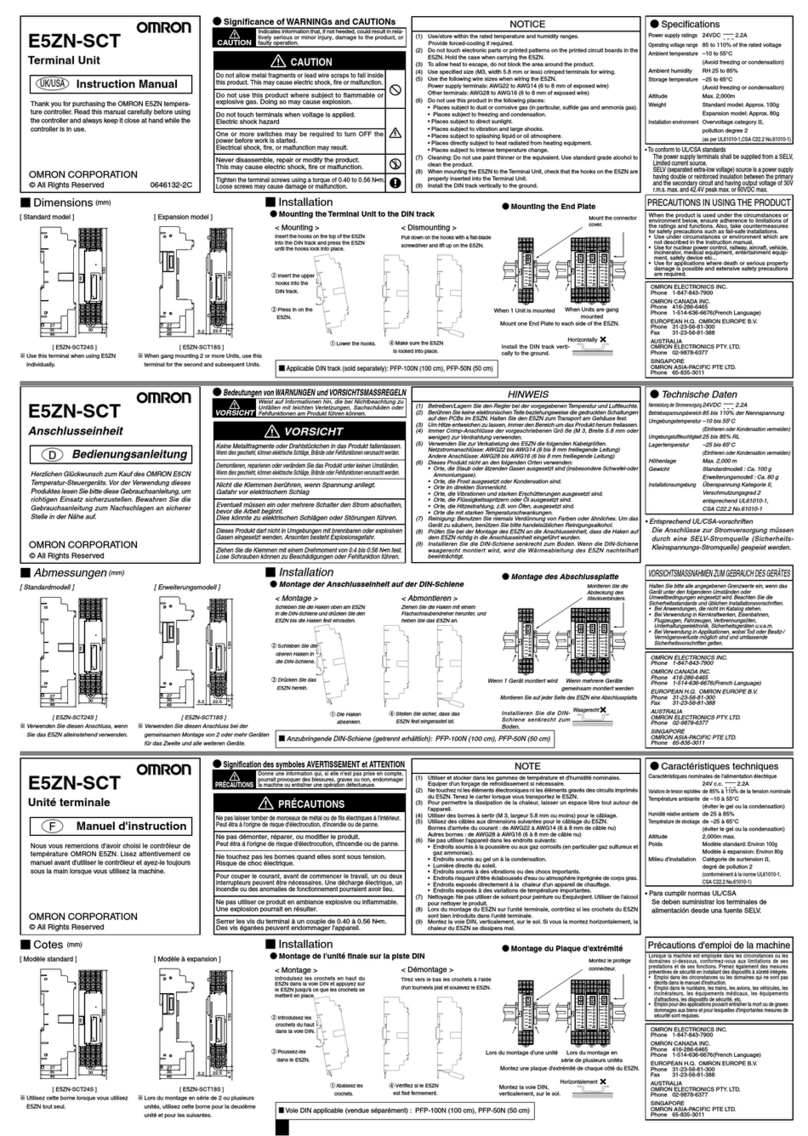
Lower the lever.
PFP-M
Vertically: OK Horizontally: Not OK
⑥
⑤
SW2
SW1
ERROR
OCC
SD/RD
READY
CN1
G3ZA
B1
B2
B3
B4
B5
B6
B7
B8
B9
OUT2
OUT1
ch2
DC12V
DC12V
TC
+
+
+
–
–
A
B
B
Voltage
output
Voltage
output
V
mA
+
–
+
ch1
TC
+
–
A
B
B
V
mA
+
–
+
A1
A2
A3
A4
A5
A6
A7
A8
A9
OUT4
OUT3
ch4
DC12V
DC12V
TC
+
+
+
–
–
A
B
B
V
mA
+
–
+
ch3
TC
+
–
A
B
B
V
mA
+
–
+
Analog
input
Pt
input
TC
input
B1
B2
B3
B4
B5
B6
B7
B8
B9
OUT2
OUT1
ch2
DC12V
DC12V
TC
+
+
+
–
–
A
B
B
V
mA
+
–
+
ch1
TC
+
–
A
B
B
V
mA
+
–
+
A1
A2
A3
A4
A5
A6
A7
A8
A9
OUT4
OUT3
CT2
CT1
EV2
COM
EV1
※
B1
B2
B3
B4
B5
B6
B7
B8
B9
OUT2
OUT1
ch2
4-20/0-20mA DC
4-20/0-20mA DC
TC
+
+
+
–
–
A
B
B
V
mA
+
–
+
ch1
TC
+
–
A
B
B
V
mA
+
–
+
A1
A2
A3
A4
A5
A6
A7
A8
A9
OUT4
OUT3
EV2
COM
EV1
※
* Cannot be used for the Gradient Temperature Control Model (EJ1G).
1
2
3
4
5
6
7
8
9
Port A
Port A
Port A (Connector)
RS-485
A(–)
B(+)
Port B
Port B
RS-485
A(–)
B(+)
B(+)
A(–)
SUB2
COM
SUB1
COM
B(+)
A(–)
+
–
DC24V
DC24V
–
+
Input
power supply
SUB2
SUB1
COM
Both of these ports
cannot be used at
the same time.
Donotusethisport
whenusingan
AdvancedUnit.
DO NOT USE
1
2
3
4
5
6
7
8
9
10
Operation indicator Pin 6 of SW2 = OFF
Pin 6 of SW2 = ON (See note 2.)
PWR/1
(green) Lit when power is supplied.
Lit when output 1 is ON.
RUN/2 (green)(See note 1.)
Lit during operation. Lit when output 2 is ON.
ERR/3 (red)
Flashes or lights when an error occurs.
Lit when output 3 is ON.
ALM/4 (red)
Lights when an alarm occurs.
Lit when output 4 is ON.
COM1
(orange)
Flashes during communications on End Unit port A.
COM2
(orange)
Flashes during communications on End Unit port B.
COM3
(orange)
Flashes during communications with the G3ZA.
Note 1.
Functions only on Modular Temperature Control Models (EJ1N).
Note 2. Functions only on Basic Units of Modular Temperature
Controller models (EJ1N).
Indicatesa potentially hazardoussituationwhich,if
notavoided,islikelytoresultinminorormoderate
injury or property damage. Read this manual
carefullybeforeusingtheproduct.
CAUTION
EJ1
Temperature controller
1)
The product is designed for indoor use only. Do not use the product outdoors or in any of the following locations.
• Places directly subject to heat radiated from heating equipment.
• Places subject to splashing liquid or oil atmosphere.
• Places subject to direct sunlight.
• Places subject to dust or corrosive gas (in particular, sulfide gas or ammonia gas).
• Places subject to intense temperature change.
• Places subject to icing or condensation.
• Places subject to vibration or strong shocks.
2)
Use and store the product within the rated temperature and humidity ranges. Provide forced-cooling if required.
3)
To allow heat to escape, do not block the area around the product. Do not block the ventilation holes on the product.
4) Be sure to wire properly with correct polarity of terminals.
5) Use specified size (M3, width 5.8 mm or less) crimped terminals for wiring. To connect bare wires to the
terminal block, use copper braided or solid wires with a gage of AWG22 to AWG14 (equal to cross-
sectional area of 0.326 to 2.081 mm
2
) for power supply lines and a gage of AWG28 to AWG16 (equal to
cross-sectional area of 0.081 to 1.309 mm
2
). (The stripping length is 6 to 8 mm.)
Up to two wires of same size and type, or two crimped terminals can be inserted into a single terminal.
6) Do not wire terminals that do not have an identified use.
7) Allow as much space as possible between the product and devices that generate a powerful high-
frequency or surge. Separate the high-voltage or large-current power lines from other lines, and avoid
parallel or common wiring with the power lines when you are wiring to the terminals.
8) Use the product within the rated load and power supply.
9) Make sure that the rated voltage is attained within 2 seconds of turning ON the power.
10) Make sure that the product has 30 minutes or more to warm up after turning ON the power before
starting actual control operations to ensure the correct temperature display.
11) The switch or circuit breaker must be within easy reach of the operator, and must be marked as a
disconnecting means for this unit.
12) Do not use paint thinner or similar chemical to clean with. Use standard grade alcohol.
13) Design the system (e.g., the control panel) allowing leeway for the delay required before product outputs
are valid after turning ON power to the product.
14) Never touch the electronic components, connectors, or patterns on product boards with your bare
hands. Always hold the product by the case. Inappropriately handling the product may occassionally
damage internal components due to static electricity.
15) Use a switch, relay, or other device with contacts to turn OFF the power supply quickly. Gradually
lowering the voltage of the power supply may result in incorrect outputs or memory errors.
16) Do not touch the electronic components with your hands or subject them to shock when removing the
terminal block.
17) Connect only the specified number of products in only a specified configuration.
18) Mount the product to a DIN Rail mounted vertically to the ground.
19) Always turn OFF the power supply before wiring the product, replacing the product, or changing the
product configuration.
20) Attach the enclosed cover seal to the connector opening on the left end product during installation.
21) Do not use port B on the End Units when using port C on Advanced Units.
Precautions for Safe Use
●Key to Warning Symbols
Instruction Manual
Thank you for purchasing the OMRON Product. To
ensure the safe application of the Product, only a
professional with an understanding of electricity and
electric devices must handle it. Read this manual
carefully before using the Product and always keep it
close at hand when the
Product is in use.
Suitability for Use
CAUTION
Do not touch the terminals while power is being supplied.
Doing so may occasionally result in minor injury due to electric shock.
Use a power supply that complies with the reinforced insulation
specified in IEC 60664 for the EJ1 external power supply or the power
supply connected to the EJ1. If non-compliant power supplies are
used, electric shock may occasionally result in minor injury.
Do not allow pieces of metal, wire clippings, or fine metallic shavings
or filings from installation to enter the product. Doing so may
occasionally result in electric shock, fire, or malfunction.
Do not use the product where subject to flammable or explosive gas.
Otherwise, minor injury from explosion may occasionally occur.
Never disassemble, modify, or repair the product or touch any of the
internal parts.
Minor electric shock, fire, or malfunction may occasionally occur.
Tighten the terminal screws to between 0.40 and 0.56 N・m. Loose
screws may occasionally result in fire.
Set the parameters of the product so that they are suitable for the
system being controlled. If they are not suitable, unexpected operation
may occasionally result in property damage or accidents.
A malfunction in the product may occasionally make control operations
impossible or prevent alarm outputs, resulting in property damage. To
maintain safety in the event of malfunction of the product, take
appropriate safety measures, such as installing a monitoring
device on a separate line.
Gradient temperature control controls the average temperature for
multiple channels. Therefore, if a heater burnout occurs during gradient
temperature control, the temperature for that channel will drop and the
temperature for the other channels will rise, which may occasionally result
in property damage. During gradient temperature control, provide safety
measures using information such as using the heater burnout alarm and
temperature data for each channel.
EN
●Warning Symbols
Safety Precautions
OMRON CORPORATION
©All Rights Reserved
1132575-5A
EJ8
OMRON shall not be responsible for conformity with any standards, codes, or regulations that
apply to the combination of the products in the customer's application or use of the product.
Take all necessary steps to determine the suitability of the product for the systems, machines,
and equipment with which it will be used.
Know and observe all prohibitions of use applicable to this product.
NEVER USE THE PRODUCTS FOR AN APPLICATION INVOLVING SERIOUS RISK TO
LIFE OR PROPERTY WITHOUT ENSURING THAT THE SYSTEM AS A WHOLE HAS BEEN
DESIGNED TO ADDRESS THE RISKS, AND THAT THE OMRON PRODUCT IS
PROPERLY RATED AND INSTALLED FOR THE INTENDED USE WITHIN THE OVERALL
EQUIPMENT OR SYSTEM.
See also product catalog for Warranty and Limitation of Liability.
●Specifications
Power supply voltage
24 VDC 5A (at max. DC load)
Operating voltage range
85% to 110% of the rated voltage
Power consumption
Basic Unit: TC4 5 W max. (at max. DC load)
TC2 4 W max. (at max. DC load)
Indication accuracy
Thermocouple, Platinum Resistance Thermometer
Input: (±0.5% of indication value or ±1˚C,
which is greater) ±1 digit max.
Analog Input:
(±0.5% F/S) ±1 digit max.
CT Input:
(±5% F/S) ±1 digit max.
Control output Voltage output: 12 VDC, 21 mA max.
Current output: 0 to 20 mA DC, 4 to 20 mA DC
load of 500 Ωmax.
Transistor output: 30 VDC, 100 mA max.
Auxiliary output Transistor output: 30 VDC, 50 mA max.
Control method ON/OFF or advanced PID
Ambient temperature
Operating –10 to 55˚C
*
Storage –25 to 65˚C
(with no freezing or condensation)
* Ambient Temperature according to
UL61010C-1: –10 to 40˚C
Ambient humidity Operating RH 25% to 85%
Storage RH 25% to 85%
Inrush current (POWER)
Individual Unit: 15 A max.
Weight End Unit: 70 g
Basic Unit: 180 g
Degree of protection Rear case, End Unit case: IP20
Terminal section: IP00
Installation environment
Overvoltage category II, pollution degree 2
(as per IEC 61010-1)
Altitude 2,000 m max.
Event inputs Output current: Approx. 4 mA
Contact input ON: 1 kΩmax.,
OFF:100 kΩmin.
No-contact input ON: Residual voltage of 1.5 V max.,
OFF: Leakage current of 0.1 mA max.
Max. heater current Single-phase, 100 A (AC)
Memory protection EEPROM (non-volatile memory)
(Number of write operations: 100,000)
■Wiring
●Dimensions (mm)
■Display
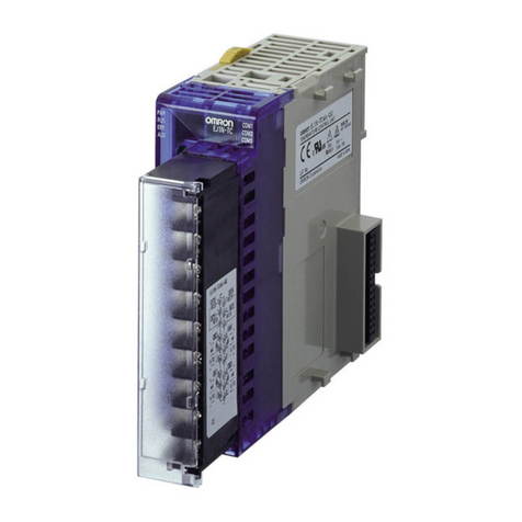
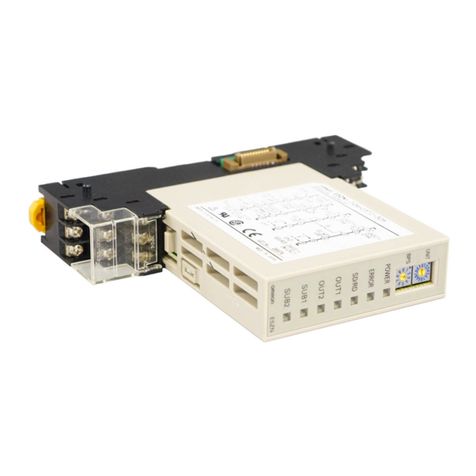
●Names of Parts on Front Panel
■Specification Settings
●Switch Operation
●Operation Indicators
●Installation
• Connecting Units
[EJ1□-TC: Basic Unit] [EJ1C-EDU: End Unit]
• Mounting to the DIN Rail
• Wiring Procedure for Screw-Less Clamp Terminals
• Removing the Terminal Block
1. Align the connector and
connect the Units to
each other. Connect and
End Unit to the Unit on
the right end. (Up to 16
Units can be connected
side by side.)
<Mounting>
Insert the hooks on the top of the EJ1 into the DIN Rail
and press the EJ1 until the hooks lock into place.
②Insert the upper hooks
into the DIN Rail.
③Press in
on the
EJ1. ①Lower the
hooks. ④Make sure the
EJ1 is locked
into place.
Flat-blade Screwdriver
There are two holes for each terminal.
The hole on the right is the operating
hole; the hole on the left is the wire hole.
Insert a flat-blade screwdriver with a
width of 2.5 mm into the operating hold
and then wiring into the wire hole. The
wire will be clamped when the
screwdriver is removed.
Use crimp terminals for wiring that match
the cross-sectional area of the wiring
material.
• We recommend the crimp terminals:
Weidmuller H-sleeve series
●To Conform to UL/CSA Standards
•
The power supply terminals must be supplied from a
SELV, limited-current source.
A SELV (safety extra-low voltage) source is a power supply
having double or reinforced insulation between the primary
and the secondary circuits and having an output voltage of
30 V r.m.s. max. and 42.4 V peak max. or 60 VDC max.
•
This is a class A product. In residential environment areas
it may cause radio interference, in which case the user
may be required to take adequate measures to reduce
interference.
●Functional insulation is provided between the power supply,
input, output, and power supply terminals. If reinforced or
double insulation is required, use a power supply that
complies with the reinforced or double insulation standards
specified in IEC 60664 for the EJ1 external power supply
and for the power supply connected to the EJ1.
Connect the G3ZA
harness to the CN1
connector on the
bottom of the Unit.
Connect the black line
with a white stripe to
terminal 7 on the G3ZA
and the black line with
no stripe to terminal 8.
<Dismounting>
Pull down on the
hooks with a flat-blade
screwdriver and lift up
on the EJ1.
Mount one End Plate to each
side of the EJ1 (PFP-M End
Plates are included with the
End Unit).
To mount an End Plate, hook
the bottom of the End Plate on
the bottom of the DIN Rail ⑤,
place the top of the End Plate
on the DIN Rail ⑥, and then
pull down on the End Plate.
Tighten the screw on the End
Plate to secure it.
2.
Slide the yellow sliders on the
tops and bottoms of the Units
until they click into place.
•Check that the EJ1 is turned OFF before operating
the switches. Settings are valid only when power is
supplied.
•Set the switches with a small flat-blade screwdriver.
Do not set the switches midway between settings.
•SW1 is set to 1 and SW2 pins are all set to OFF in the
default settings.
●Setting the Unit Number
●Setting SW2
SW1 and SW2 can be used together to set the unit number to between 00 and 63.
The factory setting is unit number 01.
3. Attach the cover seal to
the connector on the Unit
on the left end.
1. Press down the
terminal block
levers.
2. Pull out the
terminal
block.
B1
B2
B3
B4
B5
B6
B7
B8
B9
B10
A1
A2
A3
A4
A5
A6
A7
A8
A9
A10
SW1
SW2
In the pack: • Basic Unit
• Instruction manual
In the pack: • End Unit
• Instruction manual
• End Plate
• Cover seal
OMRON ELECTRONICS LLC
One Commerce Drive Schaumburg, IL 60173-5302 U.S.A
Phone 1-847-843-7900
Telephone Consultation 1-800-55-OMRON
FAX 1-847-843-7787
OMRON EUROPE B.V.
Wegalaan 67-69 P.O. BOX 13 2130 AA Hoofddorp The
Netherlands
Phone 31-23-56-81-300
FAX 31-23-56-81-388
OMRON ASIA PACIFIC PTE LTD
83 Clemenceau Avenue, #11-01 UE Square, Singapore
239920
Phone 65-6-835-3011
FAX 65-6-835-2711
OMRON Corporation
Shiokoji Horikawa, Shimogyo-ku, Kyoto 600-8530 JAPAN
For detailed operating instructions, please refer to the EJ1
Modular Temperature Controller User's Manual (Cat. No.
H142) or the EJ1 Modular Temperature Controller
(Gradient Temperature Control Model) User's Manual (Cat.
No. H143).
Install the DIN Rail vertically
to the ground.
* Do not connect an End Unit directly to an Advanced Unit.
* Always connect an End Unit to the right side of a Basic Unit.
* This Unit cannot be connected to the CJ1 Series.
* Use the EJ1G-□□ in the configuration when performing gradient temperature control, and use the EJ1N-□□
when not performing gradient temperature control.
* When removing the terminal block and replacing the Unit, make sure that the new Unit matches the original Unit.
■Applicable DIN Rail (sold
separately):
PFP-100N (100 cm), PFP-50N
(50 cm)
Precautions for Correct Use
EJ1C-CBLA050
(sold separately)
Length of cable: 5m
Set SW2 to 3 (57.6
kbps).
●Connections
• EJ1□-TC4□-□□□□ • EJ1□-TC2□-Q□□□ • EJ1□-TC2□-C□□□ • EJ1C-EDUA-□FLK
• EJ1C-EDUC-□FLK
* Terminals A10 and B10 of the screw-less clamp terminals are not used.
* Port A (Connector) is used only to connect the Temperature Controller to a computer when using the Setup Tool.
E58-CIFQ1 USB-Serial Conversion Cable is required for the connection. (Do not use the product with the Cable left permanently
connected.) Refer to the Instruction Manual provided with the USB-Serial Conversion Cable for details on connection methods.
* When wiring a voltage input, be sure to connect the correct terminals. Incorrect wiring may cause EJ1 failure.
• Connecting to the G3ZA (EJ1□-TC□□-□□□□)
• Refer to the G3ZA Instruction Manual for wiring
methods.
SW2
Pin 3
Pins
4 and 5
Pin 6
Pin 7
Pin 8
Description
Set to ON when using the Modbus communications protocol for port B.
OFF: The setting for port B communications protocol is used.
ON: Modbus is used.
Set the baud rate for port B.
4 = OFF, 5= OFF: Use port B baud rate setting (default: 9.6 kbps).
4 = ON, 5= OFF: 19.2 kbps
4 = OFF, 5= ON: 38.4 kbps
4 = ON, 5= ON: 115.2 kbps
Set to ON to display the output status on the operation indicators.
OFF: The operation status is displayed (PWR, RUN, ERR, and ALM).
ON: The output status is displayed (outputs 1, 2, 3, and 4).
Note: Normally keep this pin set to OFF so that the operation status
can be checked.
Set to ON when using the G3ZA.
Used when using an Advanced Unit and distributed installation.
(Refer to the User's Manual for details.)
