manuals.online logo
Brands
  1. Home
  2. •
  3. Brands
  4. •
  5. Ops-Core
  6. •
  7. Motorcycle Accessories
  8. •
  9. Ops-Core MBS User manual

Ops-Core MBS User manual

ACCESSORIES
KIT INCLUDES:
(1) Skull Mounting System MBS equipped with (1) ½” Front Pad , (1) ¼” Top Pad, (1) ¼” Rear Pad, (1) ¼” Left Side Pad, (1) ¼” Right Side Pad;
and additional (1) ½” Rear, (1) ½” Left Side, and (1) ½” Right Side Pads
This product is covered by one or more patents. For more information visit www.gentexcorp.com/patents
UM-1063 REV.A
© 2019 Gentex Corporation. Ops-Core is a registered trademark of Gentex Corporation or its afliates. VELCRO® is a registered trademark of Velcro BVBA.
ATTACHMENT
The Modular Bungee Shroud and Rear
Exterior VELCRO®provide convenient and
secure ways to attach and
detach various
accessories to different positions, allowing
for personalized customization.
The Skull Mounting System MBS does not provide any type of protection for the head and does not offer any protection against neck, spinal, or brain injuries including those caused by rotational forces. Inspect the Skull Mounting System MBS before each use. Make sure the adjustment
dials, plastic hardware, stitching, chinstrap, and t system components are not damaged, cracked, deformed, loose or showing signs of excessive wear. If they do, replace them or the Skull Mounting System MBS.
Unless an individual product is covered by a separately issued warranty, Gentex warrants that all ballistic helmet shells will be free from defects in material or workmanship under normal use and service for a period of five (5) years from the date of delivery. Unless an
individual product is covered by a separately issued warranty, Gentex warrants that all helmet components, accessories, peripherals, and parts will be free from defects in material or workmanship under normal use and service for a period one (1) year from the date of
delivery. All repair covered by this warranty shall be performed at Gentex’s factory, or other such warranty repair facilities of Gentex as designated by Gentex unless Gentex specifically directs that repair services be performed at another location. Any defect corrected and
found to be within this scope of the warranty will be repaired by Gentex and all charges for labor and material will be borne by Gentex. If it is determined that either no fault exists in Gentex, or the damage to be repaired was caused by negligence of the user, its agents,
employees or customers, you agree to pay all charges associated with each such repair. No statement, recommendation or assistance made or offered by Gentex through its representatives to the user, its agents, employees, or customers in connection with the purpose or
intended use of any Gentex’s product shall be or constitute a waiver by Gentex of any of the provisions of this warranty or change Gentex’s liability under this warranty.
EXCEPT WHERE PROHIBITED BY LAW, THE WARRANTY DESCRIBED ABOVE CONSTITUTES THE SOLE WARRANTY MADE BY GENTEX EITHER EXPRESSED OR IMPLIED. THERE ARE NO OTHER WARRANTIES EXPRESSED OR IMPLIED THAT EXTEND BEYOND THE FACE HEREOF,
HEREIN, INCLUDING THE IMPLIED WARRANTIES OF MERCHANTABILITY AND FITNESS FOR A PARTICULAR PURPOSE. IN NO EVENT SHALL GENTEX BE LIABLE FOR ANY INCIDENTAL, CONSEQUENTIAL, OR SPECIAL DAMAGES EVEN IF ADVISED OF SUCH DAMAGES, AND THE
USER, ITS AGENTS, EMPLOYEES, OR CUSTOMERS REMEDIES SHALL BE LIMITED TO SOLELY TO THE REPAIR OR REPLACEMENT OF NONCONFORMING UNITS OR PARTS, WHICH AMOUNT SHALL NOT EXCEED THE TOTAL PURCHASE PRICE OF THE PRODUCT UNDERWARRANTY.
Any tampering, misuse or negligence in handling or use of the product renders the warranty void. Further, the warranty is void if, at any time, the user, its agents, employees or customers attempts to make any internal changes to any of the components of a product; if at
any time the power supplied to any part of the product exceeds the rated tolerance; if any external device attached by the user, its agents, employees or customers creates conditions exceeding the tolerance of the product; or if any time the serial number plate is removed
or defaced. OPERATION OF THE PRODUCTS THAT RENDERS THIS WARRANTY VOID WILL BE DEFINED TO INCLUDE ALL OF THE POSSIBILITIES DESCRIBED IN THIS SECTION, TOGETHERWITH ANY PRACTICE THAT RESULTS IN CONDITIONS EXCEEDING THE DESIGN TOLERANCE
OF THE PRODUCTS.
GENTEX CORPORATION LIMITED WARRANTY
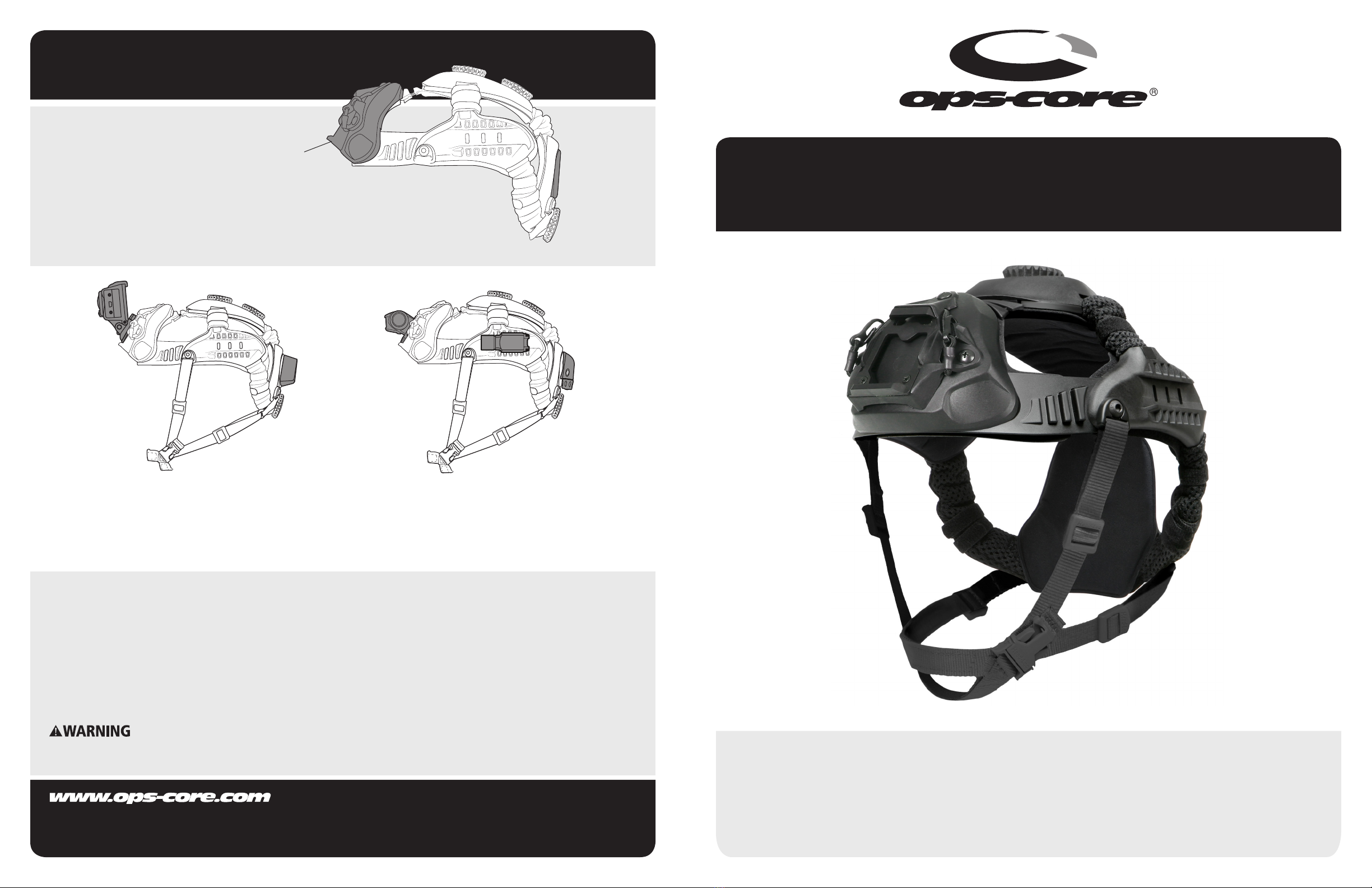
VIDEO CAMERAS
The Skull Mounting System MBS provides mounting options for various types of video
cameras. A Counterweight can be attached to the rear of the Skull Mounting System
MBS to counterbalance the weight of accessories attached to the Front Plate.
ILLUMINATION / IFF
Skull Mounting System MBS allows for streamlined mounting of devices
such as IR illuminators, lights, and IFF devices. The Rear Exterior VELCRO®
provides a quick way to attach and detach accessories.
Rear Exterior
VELCRO® &
Mounting
Plate for
Counterweights
Modular Bungee
Shroud
SKULL MOUNTING SYSTEM MBS
OPERATOR’S MANUAL
FIT & ADJUSTMENTINTRODUCTION
COMFORT PAD SETUP
The Skull Mounting System MBS is designed to t the majority of
head sizes. However, some users with smaller head sizes may nd
the thin pads to result in a loose t. If this occurs, replace the back
and side pads with the thicker comfort pads shown in dark grey.
Right Side
COUNTERWEIGHT KIT
(OPTIONAL)
Kit includes (1) Small and (1) Large Counterweight with
corresponding hardware.
Attached
Counterweight
Large Counterweight
(with 1¼” Screws)
Small Counterweight
(with 5/8” Screws)
(Back of Skull Mounting System MBS)
COUNTERWEIGHT
ATTACHMENT
NOTE: ONLY ATTACH A COUNTERWEIGHT IF YOU
NEED TO COUNTERBALANCE AN ATTACHMENT
AT THE FRONT OF THE Skull Mounting System MBS.
Align Counterweight holes to the holes on the back of the Skull
Mounting System MBS. Hold Counterweight in place and use your
fingers to loosely attach a screw through the Counterweight and
Skull Mounting System MBS. Repeat for the remaining 2 holes.
Finish by using a screwdriver to tighten all 3 screws from the
outside of the Counterweight, making sure the Counterweight
is securely fastened to the Skull Mounting System MBS.
Rear
Left Side
SKULL MOUNTING SYSTEM MBS SETUP
•Turn Adjustment Dials counterclockwise (left) to make sure the Skull Mounting System MBS
is fully open.
•Place open Skull Mounting System MBS on your head so that the Universal Front Plate is
centered over the bridge of your nose. Begin adjustment by firmly pressing down on the
top of the Universal Front Plate while tightening the Rear Adjustment Dial (turn clockwise
to tighten).
•The distance from the top of the eyebrow to the bottom of the Skull Mounting System MBS
should be approximately 0.5” - 1” as shown. The bottom of the Rear Pad should rest above
nape of the neck.
CHINSTRAP OPERATION
•Fasten the Chinstrap Buckle. With both
hands, pull the two Rear Head-Loc
Sliders on the lower webbing straps
toward your chin until snug.
•With both hands, pull the two Front
Head-Loc Sliders on the webbing straps
that come from the front temples of the
Skull Mounting System MBS toward
your chin until snug.
TIGHTEN
(Skull Mounting System MBS Fully Closed)
TURN DIALS CLOCKWISE TO TIGHTEN
LOOSEN
(Skull Mounting System MBS Fully Open)
TURN DIALS COUNTERCLOCKWISE TO LOOSEN
FIT DIAL
OPERATION
•Proceed to tighten the front and rear
Top Adjustment Dials until the Skull
Mounting System MBS fits securely
on head. Readjust dials as desired to
achieve comfortable fit and positioning.
•Once the front and rear Top Adjustment
Dials are set, the Rear Adjustment Dial
may need to be tightened again.
Front
Head-Loc
Slider
Front
Head-Loc
Slider
Rear
Head-Loc
Slider
ABOUT YOUR SKULL MOUNTING SYSTEM MBS
This manual covers the basic operating and tting instructions for the Ops-Core Skull Mounting System MBS. The Skull Mounting
System MBS is a multi-purpose headgear integration device that is compatible with a variety of attachments. The three dial
adjustment system accommodates a full range of head shapes and sizes. Adjustment Dial
Modular Bungee
Shroud (MBS)
Chinstrap Buckle
(LED Version Available)
Side Rail
Rear
Comfort Pad
Head-Loc™
Adjustment
Sliders
0.5”-1”
Rear
Adjustment
Dial
Top
Adjustment
Dials
Chinstrap
Buckle
Inside View

Other Ops-Core Motorcycle Accessories manuals

Ops-Core Fast Bump User manual

Ops-Core

Ops-Core Fast Bump User manual

Ops-Core MOTO VISOR User manual

Ops-Core

Ops-Core MOTO VISOR User manual

Ops-Core SKULL User manual

Ops-Core

Ops-Core SKULL User manual

Ops-Core Mesh Helmet Cover User manual

Ops-Core

Ops-Core Mesh Helmet Cover User manual

Ops-Core FAST LOW PROFILE BALLISTIC APPLIQUÉ User manual

Ops-Core

Ops-Core FAST LOW PROFILE BALLISTIC APPLIQUÉ User manual

Ops-Core FAST User manual

Ops-Core

Ops-Core FAST User manual

Ops-Core FAST SF User manual

Ops-Core

Ops-Core FAST SF User manual

Ops-Core ACH User manual

Ops-Core

Ops-Core ACH User manual

Ops-Core ACH-ARC User manual

Ops-Core

Ops-Core ACH-ARC User manual

Ops-Core UNIVERSAL EXTERIOR LOOP KIT User manual

Ops-Core

Ops-Core UNIVERSAL EXTERIOR LOOP KIT User manual

Ops-Core MOTO MANDIBLE User manual

Ops-Core

Ops-Core MOTO MANDIBLE User manual

Ops-Core FORCE-ON-FORCE MANDIBLE User manual

Ops-Core

Ops-Core FORCE-ON-FORCE MANDIBLE User manual

Ops-Core Mesh Helmet Cover User manual

Ops-Core

Ops-Core Mesh Helmet Cover User manual

Popular Motorcycle Accessories manuals by other brands

hepco & becker 5032527 00 01 manual

hepco & becker

hepco & becker 5032527 00 01 manual

kellermann Micro 1000 PL installation manual

kellermann

kellermann Micro 1000 PL installation manual

Contimac Weldmeister XL manual

Contimac

Contimac Weldmeister XL manual

JIMS 1824 instruction sheet

JIMS

JIMS 1824 instruction sheet

hepco & becker SportRack 670707 00 01 quick guide

hepco & becker

hepco & becker SportRack 670707 00 01 quick guide

KTM 78112964000 Information

KTM

KTM 78112964000 Information

Shark Heritage manual

Shark

Shark Heritage manual

KTM 95814910044C1 Fitting instructions

KTM

KTM 95814910044C1 Fitting instructions

NZI Helmets Street Track owner's manual

NZI Helmets

NZI Helmets Street Track owner's manual

Suzuki 93100-2181 Series installation instructions

Suzuki

Suzuki 93100-2181 Series installation instructions

LAZER JAZZ user guide

LAZER

LAZER JAZZ user guide

Dynojet Power commander V installation instructions

Dynojet

Dynojet Power commander V installation instructions

kellermann KH 1000 Mounting instructions

kellermann

kellermann KH 1000 Mounting instructions

Braun Classic HLH 18 manual

Braun

Braun Classic HLH 18 manual

Central Hydraulics 91764 Set up and operating instructions

Central Hydraulics

Central Hydraulics 91764 Set up and operating instructions

Segway NB-400 user manual

Segway

Segway NB-400 user manual

Dynojet POWER  COMMANDER FC installation instructions

Dynojet

Dynojet POWER COMMANDER FC installation instructions

SUOMY MrJump User instructions

SUOMY

SUOMY MrJump User instructions

manuals.online logo
manuals.online logoBrands
  • About & Mission
  • Contact us
  • Privacy Policy
  • Terms and Conditions

Copyright 2025 Manuals.Online. All Rights Reserved.