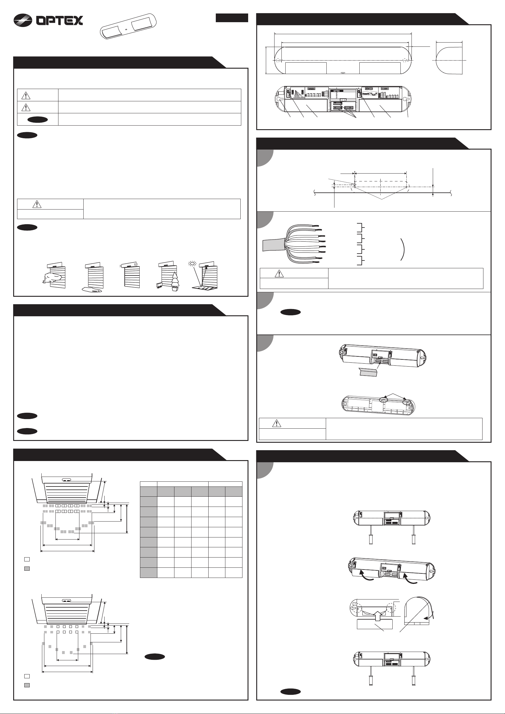
manuals.online logo
Brands
  1. Home
  2. •
  3. Brands
  4. •
  5. Optex
  6. •
  7. Security Sensor
  8. •
  9. Optex OA-6500S T User manual

Optex OA-6500S T User manual

OA-6500S T
ENGLISH
5925242 JUN 2017
Specifications
: OA-6500S T
: Black
: 8'2" (2.5m) to 21'4" (6.5m)
: See Detection area
: Active infrared reflection method
(All presence detection)
: 1st and 2nd rows: -15° to +5°
3rd row: +30° to +50°
: 12 to 24VAC ±10% (50 / 60Hz)
12 to 30VDC ±10%
: < 2.5W (< 3.5VA at AC)
: Green / Stand-by
Red / 1st row detection
Orange / 2nd and 3rd rows detection
Model
Color
Mounting height
Detection area
Detection method
Depth adjustment
Power supply
Power consumption
Operation indicator
: 3rd row detection
N.C. / N.O. selectable
50V 0.3A MAX.(Resistance load)
: Opto coupler
Voltage 5 to 30VDC
Current 6mA Max. (30VDC)
: 1st or 2nd row detection
N.C. / N.O. selectable
50V 0.3A MAX.(Resistance load)
: Approx. 0.5sec.
: < 0.3sec.
: -4°F to 131°F(-20°C to +55°C)
: < 80%
: IP44
: 21.2 oz (600g)
: 1 Cable 25' (7.62m)
2 Mounting screws
1 Mounting template
1 Operation manual
1 High mount window
1 Protection sticker
Activation output
Test input
Safety output
Output hold time
Response time
Operation temperature
Operating humidity
IP rate
Weight
Accessories
The specifications herein are subject to change
without prior notice due to improvements.
NOTE
NOTE
1
3
2
WARNING
Danger of electric shock.
Do not use the sensor without the cover.
When using the cable knockout, install the sensor indoors or use the rain-cover
(Separately available) otherwise electric shock or breakdown of the sensor may
occur.
4
Wire the cable to the door controller as shown below.
1.Plug the connector of the sensor.
2.Supply power to the sensor. Adjust the detection area and set the dipswitches. (See Adjustments)
1.Put the protection sticker as shown below.
Before starting the procedure, make sure that the power is turned OFF.
When passing the cable through the hole, do not tear the shield.
otherwise it may cause electric shock or breakdown of the sensor.
WARNING
Danger of electric shock.
NOTE
Installation
Grey
Grey
White
Yellow
Knockout
1'1 5/16" (338)
5/8"(16)
1 7/16"
(36.5)
1/8" (3)
Mounting holes ø1/8" (ø3.4mm)
Wiring hole ø5/16" (ø8.0mm)
The lower edge
of the header
Make sure to connect the cable correctly to the door controller before turning the power ON.
When turning the power ON or after adjusting the settings, do not enter the detection area for more
than 10 seconds in order to enable the presence detection.
When changing the settings of dipswitch, see Adjustments 3 Dipswitch settings.
See Adjustments 3-1 for settings.
12 to 24VAC (50 / 60Hz)
12 to 30VDC
[inch(mm)]
1
Adjustments
Detection window selection
ON
1 2 5 6 7 83 4
ON
1 2 5 6 7 83 4
ON
1 2 5 6 7 83 4
ON
1 2 5 6 7 83 4
ON
1 2 5 6 7 83 4
ON
1 2 5 6 7 83 4
According to the mouting height, select proper detection window.
8'2"(2.5m) to 16'5"(5.0m) : Standard window(default)
16'5"(5.0m) to 21'4"(6.5m) : High mount window
window
1. Remove the screws
2.Take the windows off.
3.Attach the windows.
4.Fix the windows with the screws.
Drill two mounting holes ø1/8" (ø3.4mm) on the header.
To pass the cable through the header, drill a wiring hole of ø5/16" (ø8mm).
Detection area
: Emitting spots
: Emitting spots (Can be eliminated)
The actual detection area may become smaller
depending on the ambient light, the color / material of
the object or the floor as well as the entry speed of
the object.
The sensor may not be activated when the entering
speed of the object or a person is slower than
50mm / sec. or faster than 1500mm / sec.
NOTE
A
B
C
D
E
F
G
Z
8'2"
(2,500)
11'6"
(3,500)
14'9"
(4,500)
18'1"
(5,500)
21'4"
(6,500)
6"
(150)
8"
(210)
11"
(280)
1'1"
(340)
1'4"
(400)
6"
(150)
9"
(220)
11"
(280)
1'1"
(340)
1'4"
(410)
1'10"
(560)
2'7"
(790)
3'4"
(1010)
4'1"
(1240)
4'10"
(1470)
2'3"
(680)
3'2"
(960)
4'1"
(1240)
4'11"
(1510)
5'11"
(1790)
4'5"
(1340)
6'2"
(1870)
7'11"
(2410)
9'8"
(2940)
11'5"
(3480)
5'1"
(1530)
7'1"
(2150)
9'1"
(2760)
9'2"
(2790)
10'10"
(3300)
11'11"
(3640)
16'9"
(5100)
21'7"
(6560)
23'9"
(7230)
28'1"
(8550)
12'7"
(3840)
17'8"
(5380)
22'8"
(6910)
25'
(7620)
29'7"
(9010)
[feet,inch(mm)]
Mounting
height
Window Standard window High mount window
Values of the chart are based on the following depth
angle adjustment settings;
[Standard window]
: Emitting spots
: Emitting spots (Can be eliminated)
2nd row
1st row
3rd row
Z
AB
C
D
F
G
E
[High mount window]
2nd row
1st row
3rd row
Z
AB
C
D
F
G
E
Mounting
height
Mounting
height
Manufacturer's statement
WARNING
CAUTION
NOTE
WARNING Do not wash, disassemble, rebuild or repair the sensor, otherwise
it may cause electric shock or breakdown of the equipment.
Danger of electric shock.
Special attention is required to the section of this symbol.
NOTE
Read this operation manual carefully before use to ensure proper operation of this product.
Failure to read this operation manual may cause improper operation and may result in serious injury or death of a person.
The meanings of the symbols are as follows.
The following conditions are not suitable for sensor installation.
- Fog or exhaust emission around the door.
- Wet floor.
- Vibrating header or mounting surface.
- Moving objects or objects that emit light near the detection area.
- Highly reflecting floor or highly reflecting objects around the door.
NOTE
1. This product is a non-contact switch intended for header mount for use on industrial door.
Do not use for any other applications.
2. When setting the sensor's detection area, make sure that there is no traffic around the installation site.
3. Before turning the power ON, check the wiring to prevent damage or malfunction of equipment connected
to the product.
4. Only use the product as specified in the operation manual provided.
5. Be sure to install and adjust the sensor in accordance with the local laws and standards of the country in
which the product is installed.
6. Before leaving the installation site make sure that the product is operating properly and instruct the building
owner/operator on proper operation of the door and the product.
7.The product settings can only be changed by an installer or service engineer. When changed, the
changed settings and the date shall be registered in the maintenance logbook accompanying the door.
Outer dimensions and part names
2 7/8"(73)
1'2 5/8"(371)
2 13/16"(72)
3/8"(10)
1'1 5/16"(338)
(1) 1st and 2nd rows adjustment screw
(2) 3rd row adjustment screw
(3) Detection window
(4) Mounting holes
(5) Dipswitches
[inch(mm)]
+50°
+30°
+40°
SW2 SW3
SW1
ON
1 2 5 6 7 83 4
ON
1 2 5 6 7 83 4
ON
1 2 5 6 7 83 4
+5
°
-15
°
-5
°
(1) (2)
(3) (3)
(4) (4)
(5)
Simultaneous output
3
2
Safety output
1
Activation output
N.O.
N.C.
2nd row output
4
5,6,7
Activation
Safety
Setting 3
Setting 4
Setting 1
Setting 2
Frequency
Make sure that Dipswitch 5 is set to “OFF” for any setting.
N.O.
N.C.
ON
OFF
8
Low
High
Depth adjustment
1st and 2nd rows 3rd row
SW1
Testinput
Power supply :12 to 24VAC±10% / 12 to 30VDC±10%
Power consumption : < 2.5W ( < 3.5VA at AC)
Activation output (When 3rd row detects.)
N.C. / N.O. selectable , 50V0.3A MAX.(Resistance load)
Safety output (When 1st or 2nd row detects.)
N.C. / N.O. selectable , 50V0.3A MAX.(Resistance load)
Test input
Opto coupler, Voltage : 5 to 30VDC, Max.
Grey
Grey
White
Yellow
White stripe
Yellow stripe
Red +
Black -
Wiring
OA-6500S T
On delay
2 sec.
Door cancel
Automatic infinite
presence detection
Sensitivity
Presence
timer
1,2
10min.
2sec.
60sec.
7,8
High
Low
Middle
S-High
3
Presence area
1st & 2nd
1st to 3rd
4
ON
OFF
5
ON
OFF
ON
OFF
ON : Active
OFF : Eliminate
6
SW3
Detection area pattern
1st and 2nd rows 3rd row
Detection area 2 (3) can not be eliminated
when dipswitch 1 (4) is not eliminated.
SW2
1 2 3 4 58
6 7
1st and 2nd rows
3rd row
: +5°
: +30°
White stripe
Yellow stripe
Red (+)
Black (-)
Safety output
Power supply
Activation output
Test input
2.Place the housing cover.
If wiring is to be exposed, break the knockout.
When changing window follow procedure below.
NOTE Please carry out operation check after changing window.
Failure to follow the instructions provided with this indication and improper handling may cause
death or serious injury.
Failure to follow the instructions provided with this indication and improper handling may cause
injury and/or property damage.
LED will be turned off about 500ms when the
sensor Test output signal works well.
2Area adjustment
Detection areas 1 to 4 shown in right figure can be eliminated
with dipswitches 1 to 4.
*Detection area 2 (3) can not be eliminated when dipswitch 1 (4)
is not eliminated.
Detection areas 5 to 8 can be eliminated with dipswitches 5 to 8.
1 2 34
5 8
6 7
ON : Active area
OFF : Eliminated area
1st row
2nd row
3rd row
Detection areas 1 to 8 correspond
to dipswitches 1 to 8
8'2"
(2.5)
11'6"
(3.5)
14'9"
(4.5)
18'1"
(5.5)
21'4"
(6.5)
3'3"
(1.0)
3'3"
(1.0)
6'7"
(2.0)
6'7"
(2.0)
9'10"
(3.0)
13'2"
(4.0)
16'5"
(5.0)
19'9"
(6.0)
22'12"
(7.0)
26'3"
(8.0)
+50° +30° +5° -15°
Unit : feet,inch(m)
Adjustments
3-5.Setting the Presence area
3-7.Setting the Door cancel
3-9.Setting the Sensitivity
Dipswitch settings
3-1.Setting the Outputs
3-2.Setting the Frequency
3-6.Setting the Automatic infinite presence detection
3
3-8.Setting the On delay 2sec.
(SW1 Dipswitch 1,2,3 and 4)
(SW3 Dipswitch 3)
ON OFF
44
1st & 2nd 1st to 3rd
33
(SW3 Dipswitch 5)
(SW3 Dipswitch 6)
ON OFF
6 6
(SW3 Dipswitch 4)
ON OFF
5 5
(SW3 Dipswithch 7 and 8)
When using more than one sensor close to each other, set
the different frequency for each sensor by combining
dipswitch 6 and 7.
(SW1 Dipswitch 6 and 7)
65 7 65 7 65 7 65 7
Setting1 Setting2 Setting3 Setting4
When people or objects enter more than 2 spot areas, this function automatically sets
the presence timer to infinity to increase safety and avoid unwanted door opening due
to sudden change in floor condition.
1 1
Activation output Safety output
N.O. N.C.
2 2
N.O N.C
When dipswitch 4 is set to "ON" the automatic infinite presence detection has priority over this function.
NOTE
7
Low Middle High S-High
With this fuction, 1st row is disabled if there are no ditection for 10sec.
If a person or vehicle enter the first row without any detection in other rows
(e.g. enter from the other side), it might cause an accident.
WARNING
Risk of getting caught.
NOTE Adjust the sensitivity to suit each installation site.
Recommended sensitivity setting in accordance with the following
mounting height.
: 8'2"(2.5m) to 11'6"(3.5m)
: 9'10"(3.0m) to 14'9"(4.5m)
: 13'2"(4.0m) to 18'1"(5.5m)
: 16'5"(5.0m) to 21'4"(6.5m)
L
M
H
S-High
ON OFF
3 3
Simultaneous output
Activation Safety
4 4
2nd row output
Make sure that dipswitch 5 is set to "OFF"
for any setting.
NOTE
1,2 : Presence timer
3 : Presence area
4 : Automatic infinite presence detection
1 : Activation output
2 : Safety output
3 : Simultaneous output
Entry into
3rd row
Inform building owner / operator of the following items
Alarm display
Refer to the Troubleshooting below when the following appears.
Check the operation according to the chart below.
Checking
Status
Image
Green Red
Entry
Outside of
detection
area
Outside of
detection
area
Entry into
2nd row
Entry into
1st row
Orange
Stand-by
Green
Stand-by
Operation indicator
Motion / Presence detection active
Power OFF
-
None
Simultaneous
output
ON
3
Simultaneous
output
OFF
3
Dipswitches <SW1>
3rd row
1st and 2nd rows
+5°
-5°
0°
SW2 SW3
SW1
ON
1 2 5 6 7 83 4
ON
1 2 5 6 7 83 4
ON
1 2 5 6 7 83 4
+30° to +50°
3rd row
adjustment screw
Right : + direction
Left : - direction
+50°
+30°
+40°
1st and 2nd rows
adjustment screw
-15° to +5°
Right : + direction
Left : - direction
+5°
-15°
-5°
[Depth adjustment]
[Right and left elimination]
1st and 2nd rows
3rd row
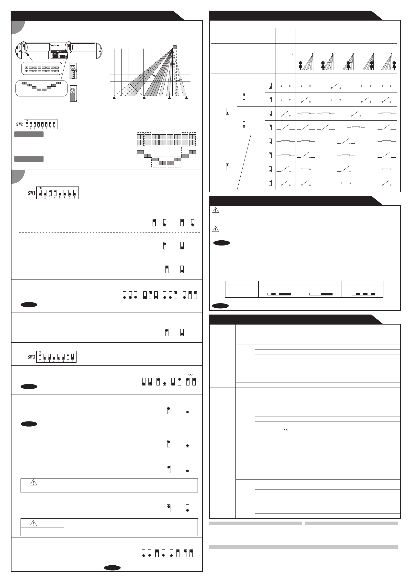
[1.Dipswitches <SW1>]
The outputs from Activation output (2nd and 3rd rows) and
Safety output (1st row) can be selected separately from N.C.
and N.O. by dipswitch 1 and 2.
The output timing from "Activation output" and "Safety output" can
be changed by dipswitch 3.
With dipswitch 3 set to "ON" the output timing will be the same.
With dipswitch 3 set to "OFF" the output timing will be different.
See Checking.
The 2nd row output selectable by dipswitch 4.
With dipswitch 4 set to "ON" the output from 2nd row will be sent from
Activation output.
With dipswitch 4 set to "OFF" the output will be sent from Safety output.
See Checking.
[2.Dipswitches <SW3>]
3-3.Setting the Test input (SW1 Dipswitch 8)
Select "High" / "Low" for Test input.
The delay time between Test input and Safety output is 10msec. Low High
8 8
Test input
5 : Door cancel
6 : On delay 2sec.
7,8 : Sensitivity
3-4.Setting the Presence timer (SW3 Dipswitch 1 and 2)
Presence detection timer can be selected by combining
dipswitch 1 and 2.
To enable the presence detection, do not enter
the detection area for 10 seconds after setting the timer.
NOTE
2sec. 60sec. 10min.
1 2 1 2 1 2 1 2
With dipswitch 3 "1st & 2nd" , presence timer for 1st & 2nd rows belong to
dipswitch 1 and 2. Presence timer for 3th row automatically becomes 2 sec..
With dipswitch 3 "1st to 3rd" , presence timer will be same as all detection area,
set by combining dipswitch 1 and 2.
When dipswitch 5 is "ON" the sensor is less influenced by the door movement,
i.e. caused by wind. If the sensor does not detect for 10sec., the 1st row will be
disabled when door cancel function is"ON".
(The 1st row will be enabled again when there is detection at other rows.)
To avoid unnecessary openings due to passing objects/persons set dipswitch 6 "ON".
The sensor only activates when a person or object stays in the detection area for more
then 2 seconds.
Please do not set On delay 2sec. to "ON" when door cancel function is "ON". If both
are "ON", the sensor does not output signal unless it detects a person or object more
than 2sec and 1st row is inactive. If the person or object enter the fist row, the sensor
does not detect and door never opens.
WARNING
Risk of getting caught.
4 : 2nd row output
5,6,7: Frequency
8 : Test input
(Low)
(Middle)
(High)
(Super high)
Activation
4
2nd row
output
Safety
4
2nd row
output
Activation
output
Safety
output
Activation
output
Safety
output
N.C.
1
N.O.
1
N.C.
2
N.O.
2
N.C.
1
N.O.
1
N.C.
2
N.O.
2
Life cycle notification
Twice green blinking
Signal SaturationStatus
Operation indicator Slow green blinking
Sensor failure
Fast green blinking
Troubleshooting
Wrong wiring or connection failure.
None Wrong power supply voltage.
Wrong wiring or connection failure.
Door opens
when no one
is in the
detection area.
(Ghosting)
Unstable
Door remains
open
Presence timer is " " and sudden
change in the detection area happened.
Door does not
open when a
person enters
the detection
area.
Unstable
Proper
Dirty detection window.
Water drops on the detection window.
The detection area overlaps with that of
another sensor.
The detection area overlaps with the
door / header.
Sensitivity is too high.
Green
The automatic infinite presence
detection is "ON" and the objects or
people enter more than two spot areas.
Green
Orange Wrong wiring.
Twice
green
blinking
Signal saturation
Output relay(s) is reaching the end of
its life cycle.
The detection area overlaps with the
door / header.
Slow
green
blinking
Proper
Check the wires and connector.
Set to the stated voltage.
Check Adjustments 3-4 & 3-6.
If the problem still persists, hard-reset the sensor.
(Turn the power OFF and ON again.)
Check the wires and connector.
Wipe the detection window with a damp cloth.
(Do not use any cleaner or solvent.)
Adjust the detection area to "Deep" (Outside).
Use the rain-cover (Separately available). Or install
the sensor in a place keeping the waterdrops off.
Check Adjustments 3-2.
Set the sensitivity lower.
Remove the objects.
Or check Adjustments 3-6.
Check the wires and connector.
Adjust the detection area to "Deep" (Outside).
Remove highly reflecting objects from the
detection area. Change the area angle.
Replace the sensor.
Door operation Operation
indicator Possible cause Possible countermeasures
Sensitivity is too low.
Wrong detection area positioning. Check Detection area & Adjustments
Set the sensitivity higher.
Short presence timer. Set the presence detection timer longer.
Wrong (Safety/Activation) output setting.
Both On delay and door cancel function
are "ON".
Check Adjustments 3-1.
Set either function to "OFF"
Wrong (Safety/Activation) output setting.
Check Adjustments 3-1.
Wrong (Safety/Activation) output setting.
Fast
green
blinking
Sensitivity is too low. Set the sensitivity higher.
Dirty detection window. Wipe the detection window with a damp cloth.
(Do not use any cleaner or solvent.)
Sensor failure Contact your installer or service engineer.
7 7 78 8 8 8
OPTEX Co.,LTD.
Manufacturer
5-8-12 Ogoto Otsu 520-0101, Japan
TEL.: +81(0)77 579 8700 FAX.: +81(0)77 579 7030
WEBSITE: www.optex.net
OPTEX Technologies B.V.
European Subsidiary
Henricuskade 17, 2497 NB The Hague, The Netherlands
TEL.: +31(0)70 419 41 00 FAX.: +31(0)70 317 73 21
E-MAIL: [email protected] WEBSITE: www.optex.eu
East coast office
8510 McAlpines Park Drive, Suite 108
Charlotte, NC 28211 U.S.A.
TEL.: +1-800-877-6656 FAX.: +1(704)365-0818
WEBSITE: www.ot-inc.com
OPTEX INCORPORATED
North and South America Subsidiary
18730 S. Wilmington Avenue, Suite 100 Rancho
Dominguez CA 90220 U.S.A
TEL.: +1-800-877-6656 FAX.: +1(310)898-1098
WEBSITE: www.ot-inc.com
NOTE LED will be turned off about 500ms when the sensor Test output signal works well.
1. Do not wash the sensor with water.
2. Do not disassemble, rebuild or repair the sensor yourself, otherwise electric shock may occur.
WARNING
4. When turning the power ON, always walk-test the detection area to ensure the proper operation.
5. Do not place any objects that move or emit light in the detection area. (e.g. Plant, illumination, etc.)
NOTE
1. Always keep the detection window clean. If dirty, wipe the window with a damp cloth.(Do not use any cleaner / solvent.)
2. When the operation indicator is twice geen blinking, contact your installer or service engineer.
3. Always contact your installer or service engineer when changing the settings.
CAUTION
1. Do not paint the detection window.

Other Optex Security Sensor manuals

Optex REDSCAN mini-Pro Series User manual

Optex

Optex REDSCAN mini-Pro Series User manual

Optex HX-40 User manual

Optex

Optex HX-40 User manual

Optex inSight INS-HX-80N User manual

Optex

Optex inSight INS-HX-80N User manual

Optex OA-EDGE T User manual

Optex

Optex OA-EDGE T User manual

Optex Boundary Gard BX-80N Manual

Optex

Optex Boundary Gard BX-80N Manual

Optex AP-360B User manual

Optex

Optex AP-360B User manual

Optex Smart Line Series User manual

Optex

Optex Smart Line Series User manual

Optex CX-702 MKII User manual

Optex

Optex CX-702 MKII User manual

Optex OA-FUNXION User manual

Optex

Optex OA-FUNXION User manual

Optex OVS-6000 User manual

Optex

Optex OVS-6000 User manual

Optex FlipX Series User manual

Optex

Optex FlipX Series User manual

Optex OML-ST User manual

Optex

Optex OML-ST User manual

Optex OVS-01CC User manual

Optex

Optex OVS-01CC User manual

Optex VX-402 User manual

Optex

Optex VX-402 User manual

Optex HX-80NRAM User manual

Optex

Optex HX-80NRAM User manual

Optex OVS-50TNR User manual

Optex

Optex OVS-50TNR User manual

Optex WFX-360HW User manual

Optex

Optex WFX-360HW User manual

Optex REDBEAM Series Quick start guide

Optex

Optex REDBEAM Series Quick start guide

Optex X-ZONE User manual

Optex

Optex X-ZONE User manual

Optex AX100 User manual

Optex

Optex AX100 User manual

Optex AX-330PLUS User manual

Optex

Optex AX-330PLUS User manual

Optex CDX Series User manual

Optex

Optex CDX Series User manual

Optex HX-40 User manual

Optex

Optex HX-40 User manual

Optex RXC-DT-X5 User manual

Optex

Optex RXC-DT-X5 User manual

Popular Security Sensor manuals by other brands

DELTA DORE TYXAL DCP installation guide

DELTA DORE

DELTA DORE TYXAL DCP installation guide

Bresser 7009999 instruction manual

Bresser

Bresser 7009999 instruction manual

EUCHNER LCA 4 operating instructions

EUCHNER

EUCHNER LCA 4 operating instructions

Datalogic Smart-VS Plus Product reference guide

Datalogic

Datalogic Smart-VS Plus Product reference guide

Selcom ST 400 Cayman operating manual

Selcom

Selcom ST 400 Cayman operating manual

IOT SmartRoom user manual

IOT

IOT SmartRoom user manual

iNels RFMD-100 manual

iNels

iNels RFMD-100 manual

ITALIANA SENSORI ORO 8103-ISR067 manual

ITALIANA SENSORI

ITALIANA SENSORI ORO 8103-ISR067 manual

aquilar AquiTron AT-G-ALERT-C Installation and operation instructions

aquilar

aquilar AquiTron AT-G-ALERT-C Installation and operation instructions

LEGRAND 3445 quick start guide

LEGRAND

LEGRAND 3445 quick start guide

OCENCO M-20 instruction manual

OCENCO

OCENCO M-20 instruction manual

Fike Twinflex Multipoint 202-0003 Installation and maintenance instructions

Fike

Fike Twinflex Multipoint 202-0003 Installation and maintenance instructions

BUCKINGHAM MFG 355TQ2 Instructions & warnings

BUCKINGHAM MFG

BUCKINGHAM MFG 355TQ2 Instructions & warnings

schmersal RSS 36-I2-SD-ST manual

schmersal

schmersal RSS 36-I2-SD-ST manual

UE Systems Ultraprobe 3000 instruction manual

UE Systems

UE Systems Ultraprobe 3000 instruction manual

biosystems Toxi Plus Reference manual

biosystems

biosystems Toxi Plus Reference manual

Roland R1000 series E20 manual

Roland

Roland R1000 series E20 manual

SWARCO SW2224 manual

SWARCO

SWARCO SW2224 manual

manuals.online logo
manuals.online logoBrands
  • About & Mission
  • Contact us
  • Privacy Policy
  • Terms and Conditions

Copyright 2025 Manuals.Online. All Rights Reserved.