manuals.online logo
Brands
  1. Home
  2. •
  3. Brands
  4. •
  5. Optex
  6. •
  7. Security Sensor
  8. •
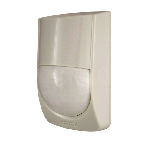
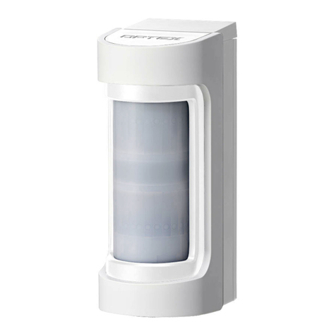
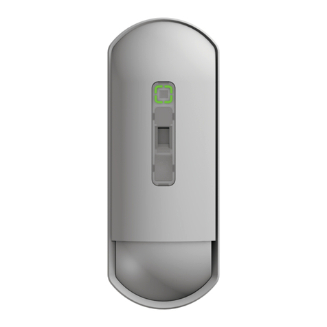
  9. Optex URX-P01WH Operation and maintenance manual

Optex URX-P01WH Operation and maintenance manual

INSTALLATION INSTRUCTIONS
No. 59-2412-0
Warning Caution
1PARTS IDENTIFICATION
2INSTALLATION HINTS
The nix sign indicates prohibition.
- 1 -
URX-P01WH : WHITE LENS MODEL
URX-P01BL : BLACK LENS MODEL
URX-P01
URX-P01
Lens
Wall/Ceiling
Bracket
[Main unit] [Back case]
[Bracket] [Cover key]
[Screws x2]
Ø4 x 30L
Included in the box
Install at a place detection area
is directed to the route of intrusion.
LED
0
0 35 ft302010
10 m
5 m
10
15 ft
0
10
15 ft
5 m
0 m
3.0 m
2.4 m
10 ft
1.8 m
10 m
(32.8 ft)
5 m
(16.4 ft)
0
8 ft
6 ft
0 ft
1
2
3 4 5 6 7 8 9 10
3DETECTION AREA
4INSTALLATION
Features
• Ultra Wide Band technology detector using 9 Ghz frequency band.
• Low false alarm risk by installed temperature fluctuations.
• Easy range selector up to 10 m/ 33 ft detection range
• Bracket included for easy angle setting.
• Self-Check function (Output when failure conditions)
ULTRA WIDE BAND IMPULSE RADAR TECHNOLOGY
TIME-OF-FLIGHT INDOOR DETECTOR
ULTRA WIDE BAND IMPULSE RADAR TECHNOLOGY
TIME-OF-FLIGHT INDOOR DETECTOR
Failure to follow the instructions provided with this indication and
improper handling may cause death or serious injury.
Failure to follow the instructions provided with this indication and
improper handling may cause injury and/or property damage.
Warning
Caution
The nix sign indicates prohibition.
Note>>
Adjust detection range if the site is
smaller than 10 m x 10 m (33 ft x 33 ft).
Do not
remove!
TOP VIEW

SIDE VIEW

Basic installation

Terminals
Range selector
rotary switch
Intrusion
route
Doorway
URX-P01
Note>>
Please refer to “ 6 SETTINGS” for range adjustment.
Caution
If detection area is set too wide,
it may detect movements outside
of the target area, which may
cause false alarms.
Adjust the detection area
according to target area.
URX-P01
1.
2.
1. Hook the top.
2. Groove the bottom
[Main unit] [Back case]
Cover Key
[Ceiling installation] [Wall installation]
STEP 1
Separate the main unit and the back case.
STEP 2
Assemble the back case and the bracket.
STEP 3
Wire to the terminals.
STEP 4
Assemble the main unit and the back case.
1
2
Wire the cable.
Assemble with the back case.
*When taking out of a box.
Note>>
Please refer to “ 8 TERMINALS” for details.
Model
Lens color
Detection method
Coverage
Mounting height
Detection speed
LED alarm indicator
Tamper alarm
Alarm output period
Warm-up period
Current consumption
Weight
Operating temperature
Environmental humidity
URX-P01
URX-P01WH : White URX-P01BL : Black
Impulse Radio (Ultra Wide Band)
2.0 ~ 3.0 m (6.5 to 10 ft)
0.3 ~ 1.5 m/sec. (1 to 5 ft/sec.)
Red LED ON When detecting, Switchable ON/OFF
2 sec.
Power input
Approx. Under 10 sec.
12 VDC (9.6 to 14.4 VDC)
30 mA (max.) at 12 VDC
Approx. 85 g (2.99 oz)
-10˚C to +50˚C (+14˚F to +122˚F)
95% max.
N.C. (30 VDC, 0.1A max.)
9
DIMENSIONS
11
COMPLIANCE
NOTE This unit is designed to detect movement of an intruder and activate an
alarm control panel.
Being only a part of a complete system, we cannot accept responsibility
for any damages or other consequences resulting from an intrusion.
10
SPECIFICATIONS
Specifications and design are subject to change without prior notice.
10 m x 10 m (33 ft x 33 ft), 90˚ wide
OPTEX CO., LTD. (JAPAN)
URL: http://www.optex.net/
OPTEX INC. (U.S.)
URL: http://www.optexamerica.com/
OPTEX DO BRASIL LTDA. (Brazil)
URL: http://www.optex.net/br/es/sec/
WIRE GAUGE 12 VDC 14 VDC
AWG 22 (0.33 mm2)
AWG 20 (0.52 mm2)
AWG 18 (0.83 mm2)
Model
Color
Angle (Default)
Angle (Max. range)
Min. angle adjustment
Installation location
GB-41
White
0°
0°
±50°
15°
5°
2.5°
Wall, Ceiling
Horizontal
Vertical
Horizontal
Vertical
Horizontal
Vertical
Unit: mm (inch)
Alarm output
Gray White
Green
Black
Red
Tamper
output
Alarm
output
Power
input
Spare
NC COM NC COM (
-
)(+)
- 2 -
FCC ID: Q54URXP01
This device complies with Part 15 of the FCC Rules.
Operation is subject to the following two conditions:
(1) This device may not cause harmful interference.
(2) This device must accept any interference received, including
interference that may cause undesired operation.
5BRACKET ADJUSTMENT
8TERMINALS
6SETTINGS
7WALK TEST
Note>>
Adjust correctly detector range according to site condition.
Angle adjustment
lever
Adjustable Lock
Power wire maximum length
(using one unit on a single wire)

1Set LED ON.
LED
ON
LED
OFF
2Conduct a walk test.
190 m
(620 ft)
300 m
(980 ft)
480 m
(1,570 ft)
420 m
(1,380 ft)
660 m
(2,170 ft)
1,050 m
(3,440 ft)
Terminals color

0
1
2
3
4
5
6
7
8
9
LED
ON
LED
OFF
LED switch

Range selector rotary switch

10m
Switch
detection
Range
1m 2m 3m 4m 5m 6m 7m 8m 9m
0 1 2 3 4 5 6 7 8 9
N.C. (30 VDC, 0.1A max.)
Lever position

15°
50°
50°
Detector specifications

Bracket specifications

Note>>
60 (2.36) 95 (3.74)
109 (4.29)
0
1
2
3
4
5
6
7
8
9
Adjust bracket angle vertically can
reduce the detection range.
Removing the bracket from the detector
1Separate the main unit and
the back case.
2Push the hook downward.
3Pull the back case forward.
103 (4.06)
112 (4.41)
124 (4.88)
1.
2.
Note>>
Caution
Conduct a walk test outside of the room to check there is no area outside.
▪Conduct a walk test at least once a year.
▪
To operate self-check function correctly, leave the detector ON for 5 minutes.

This manual suits for next models

1

Other Optex Security Sensor manuals

Optex Fit Series User manual

Optex

Optex Fit Series User manual

Optex ELITE T User manual

Optex

Optex ELITE T User manual

Optex OA-AXIS I User manual

Optex

Optex OA-AXIS I User manual

Optex CX-702 MKII User manual

Optex

Optex CX-702 MKII User manual

Optex DX-40 User manual

Optex

Optex DX-40 User manual

Optex AP-360B User manual

Optex

Optex AP-360B User manual

Optex Boundary Gard BX-80NR User manual

Optex

Optex Boundary Gard BX-80NR User manual

Optex FlipX Series User manual

Optex

Optex FlipX Series User manual

Optex FlipX Series User manual

Optex

Optex FlipX Series User manual

Optex CX-702RS User manual

Optex

Optex CX-702RS User manual

Optex AIR-SLIDE T User manual

Optex

Optex AIR-SLIDE T User manual

Optex OA-4500S User manual

Optex

Optex OA-4500S User manual

Optex Smart Line Series User manual

Optex

Optex Smart Line Series User manual

Optex VX Shield Series User manual

Optex

Optex VX Shield Series User manual

Optex CX-702S User manual

Optex

Optex CX-702S User manual

Optex RXC-RST User manual

Optex

Optex RXC-RST User manual

Optex sensor User manual

Optex

Optex sensor User manual

Optex OVS-01CC User manual

Optex

Optex OVS-01CC User manual

Optex AX-100TFR Series User manual

Optex

Optex AX-100TFR Series User manual

Optex CX-702 MKII User manual

Optex

Optex CX-702 MKII User manual

Optex HX-40 User manual

Optex

Optex HX-40 User manual

Optex HX-40RAM User manual

Optex

Optex HX-40RAM User manual

Optex AX-330PLUS User manual

Optex

Optex AX-330PLUS User manual

Optex BX SHIELD Series User manual

Optex

Optex BX SHIELD Series User manual

Popular Security Sensor manuals by other brands

Omron F39-PTG instruction sheet

Omron

Omron F39-PTG instruction sheet

Emerson Mobrey Instruction leaflet

Emerson

Emerson Mobrey Instruction leaflet

VSAIL VI-6627 Installation and operation manual

VSAIL

VSAIL VI-6627 Installation and operation manual

Delta JA-150M user manual

Delta

Delta JA-150M user manual

Paradox NV780 installation manual

Paradox

Paradox NV780 installation manual

V-TAC VT-81011 instruction manual

V-TAC

V-TAC VT-81011 instruction manual

Honeywell NFPA 1971 User's information guide

Honeywell

Honeywell NFPA 1971 User's information guide

Belkin PureAV operating instructions

Belkin

Belkin PureAV operating instructions

PCB Piezotronics W109C12/038CY010AC Installation and operating manual

PCB Piezotronics

PCB Piezotronics W109C12/038CY010AC Installation and operating manual

Inficon HLD5000 Technical handbook

Inficon

Inficon HLD5000 Technical handbook

RLE Technologies Falcon WIFI-LD quick start guide

RLE Technologies

RLE Technologies Falcon WIFI-LD quick start guide

Smanos MD2300 user manual

Smanos

Smanos MD2300 user manual

Gas Clip Technologies Multi Gas Clip Operator's manual

Gas Clip Technologies

Gas Clip Technologies Multi Gas Clip Operator's manual

CiA DT12 Handbook for the Customer

CiA

CiA DT12 Handbook for the Customer

Evikon PluraSens E2638-O2 user manual

Evikon

Evikon PluraSens E2638-O2 user manual

AJAX MotionProtect quick start guide

AJAX

AJAX MotionProtect quick start guide

LEGRAND Wattstopper DW-100-B manual

LEGRAND

LEGRAND Wattstopper DW-100-B manual

Chauvin Arnoux 760N user manual

Chauvin Arnoux

Chauvin Arnoux 760N user manual

manuals.online logo
manuals.online logoBrands
  • About & Mission
  • Contact us
  • Privacy Policy
  • Terms and Conditions

Copyright 2025 Manuals.Online. All Rights Reserved.