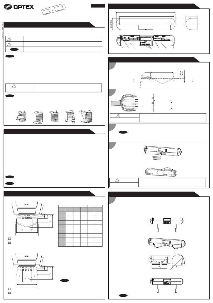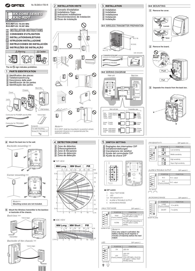
Connect the communication cables
for your particular application.
There are three communication
connectors on each module and
any of them may be used.
The power supply cable attaches
to the master module. There are two
power supply cable connectors
(one at each end of module) and
either connector can be used.
If your application includes two master
modules, the power supply cable
only goes to one master module.
Determine the desired length of the
wire shroud and cut it to length prior
to installing around the power
supply cable. Slide the wire shroud
over cable as shown in the photo
before running the wires into the
header. (cover wil not slide over the
connector)
Connect power supply cable to door
control. (refer to manual, Installation
Step 3)
Insert LED module. (See manual,
Installation Step 4)
Connect the power supply
cable to the master at either
end of the module (right).
Connecting the secondary module (Ieft) to the master (right).
Cut wire shroud to proper length prior to sliding over power
supply cable.
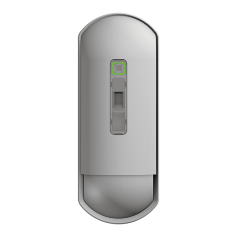
Standby
Swing side detection (Safety output 1)
Approach side detection (Safety output 2)
Incomplete initialization
Learning
Incomplete learning
Saturation
Sensor failure
Communication error
Green
Red
Orange
Red and Green blinking
Yellow blinking
Yellow and Red blinking
Slow Red blinking
Fast Red blinking
Twice Orange blinking
Status Sensor module indicator
LED Indicator
Module position
and angle
TroubleshootingWiring
Connect the communication cables to the modules, and the power
supplycable to the door controller
See the manual for additional solutions.
Ghosting/Reactivation on closing cycle :
Will not complete initialization :
Swing side sensor detecting wall or guide rail and stalling door :
LED indicates detection but door does not respond :
Initialization
Perform initial setup with door at full closed position
First step : Press and hold function switch for more than 2 seconds. This is required to recognize
dipswitch settings and number of modules. Release function switch; sensor will flash several times
and then flash Yellow/Red to indicate ready for next step (inactive area setup).
Second step (Inactive area
setup): After completing first
step (sensor flashing Yellow/
Red), press function switch for
less than 1 second.
Sensor will flash several times
and then display Green
(Standby).
Once in standby (Green),
sensor LED will change
color when in detection
(Orange for approach side
reactivation, Red for swing
side safety stall).
Set angle adjustments on modules
slightly less than mid-point.
Using the screw adjuster, set angle
adjustment on modules to slightly
less than the midpoint, using the
Red line for reference.
Try the following steps in order :
1. Reduce the angle on the lead edge module by turning the adjustor CCW 1/4 turn at
a time until ghosting stops.
2. Increase the inactive area using dipswitches A1 and B1 (refer to chart in installation
manual under Adjustments, Step 2).
3. Reposition the lead edge module slightly towards the center of the door. Do not
attempt to move the module when it is fully engaged in the extrusion or damage
may occur to the foam blocks on the clips.
1. One or more modules may be angled out too far. Reduce the angle by turning the
adjuster CCW 1/4 turn at a time and reattempt initial setup. (See Step 4)
2. Floor surface has low reflectivity. Reduce the angle on one or more modules by
turning the adjuster CCW 1/4 turn at a time and reattempt initial setup. (See Step 4)
IR saturation. One or more modules are angled too close to door panel possibly
seeing panic bar or other hardware. Increase angle of one or more modules by
turning the adjuster CW 1/4 turn at a time and reattempt initial setup. (See Step 4)
May need to use cam switch or install magnetic reed switch to inhibit sensor output at
approximately 70 degrees. Call OPTEX Technical Support to discuss possible options.
1. Swing side no stall:
a. Dipswitch B4 set improperly for safety output1 (B4 OFF is correct).
b. Improper wiring of Safety output 1. Check and repair as needed.
2. Approach side no activation:
a. Dipswitch B4 set improperly for safety output 2 (B4 On is correct).
b. Improper wiring of safety output 2. Check and repair as needed.
Module LED slow Red blinking :
Sensor module LED Yellow and Red blinking :
NOTE : This angle may need to be
reduced or increased after initialization.
(See Step 6 : Troubleshooting)
Pressing the function switch
Contact
5-8-12, Ogoto, Otsu, Shiga, 520-0101 Japan
OPTEX CO., LTD.
Manufacturer
North and South America Subsidiary
OPTEX INCORPORATED
10741 Walker Rd. Suite 300 Cypress, CA 90630 U.S.A
www.optexamerica.com Tel : +1(800)877 6656
