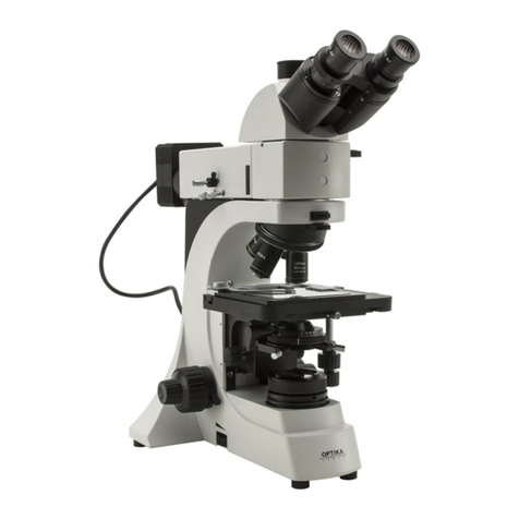
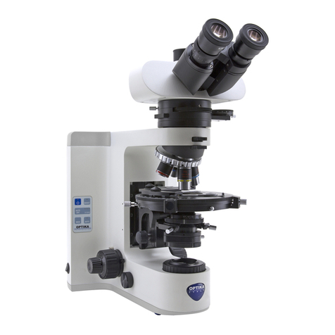
Optika B-600 MET User manual

MICROSCOPES
ITALY
OPTIKA
MICROSCOPES - ITALY
A
Ver. 2.0.0
O
PERATI
O
N MANUA
L
GUIDA UTENTE
M
ANUAL DE INSTRUCCIONES
MANUEL D’INSTRUCTIONS
B
EDIEN
U
N
GS
ANLEIT
U
N
G
Ryf AG
Bettlachstrasse 2
2540 Grenchen
tel 032 654 21 00
fax 032 654 21 09
www.ryfag.ch

Page 2
INDEX
1.0 DESCRIPTION page 3
2.0 INTRODUCTION page 5
3.0 UNPACKING AND ASSEMBLY page 5
4.0 USING THE MICROSCOPE page 7
5.0 MAINTENANCE page 10
6.0 ELECTRICS page 11
7.0 RECOVERY AND RECYCLING page 12

Page 3
1.0 DESCRIPTION
Eyepiece
Dioptric adjustment ring
Photo Port selector
lever
Objectives
Iris diaphragm
Field diaphragm Lamp housing
Stage
Nosepiece
Fine focusing knob
Coarse focusing
knob
Tension adjustment
knob
Brightfield brightness adjustment knob (epil-
lumination knob on the other side)

Page 4
1.0 DESCRIPTION
White LED housing
Darkfield lever
Diaphragm centring
screws
Metallographic features
Field diaphragm
Aperture diaphragm
Analyzer filter (rotating)
Polarizer filter Diaphragm centering
screws

Page 5
2.0 INTRODUCTION
This microscope is a scientific precision instrument designed to last for many years with a mini-
mum of maintenance. It is built to high optical and mechanical standards and to withstand daily
classroom and laboratory use.
Optika reminds you that this manual contains important information on safety and maintenance,
and that it must therefore be made accessible to the instrument users.
Optika declines any responsibility deriving from instrument uses that do not comply with this ma-
nual.
3.1 The microscope is housed in a moulded Styrofoam container. Remove the tape from the
edge of the container and lift the top half of the container. Take some care to avoid that the
optical items (objectives and eyepieces) fall out and get damaged. Using both hands (one
around the arm and one around the base), lift the microscope from the container and put it
on a stable desk.
3.2 The objectives are located in individual protective vials. Remove the objectives from the
vials and insert them into the microscope nosepiece in the order from the lowest magnifica-
tion to the highest, in a clockwise direction from the rear.
3.3 In a separate box you find the metallographic attachment. Take it out and place it onto the
top of the microscope’s stand. Then lock it in position by turning the screw with the provided
allen wrench:
3.0 UNPACKING AND ASSEMBLY
Locking screw for the
attachment

Page 6
3.4 Place the observation head into the top of the attachment and tighten the lock-screw.
3.5 Insert the eyepieces into the eye tubes.
3.6 Insert polarizer and analyzer filters into their slots in the metallographic attachment.
3.7 Connect the power cable of the epillumination to the appropriate connector on the rear:
3.0 UNPACKING AND ASSEMBLY
Connector
for LED
epillumination

Page 7
4.1 Adjust the observation head
Loosen the lock-screw, turn the observation head to a comfortable position for observation,
and then lock the lock-screw.
4.2 Place the specimen on the stage
Put the specimen on the mechanical stage (transparent glass plate). Ensure that the speci-
men is centred over the stage opening by adjusting the coaxial knobs of the stage.
Brightfield vision
4.3 Lamp settings
The microscope is fitted with a 50 W illuminator. Insert the plug of the cable into the power
socket and turn on the switch on the back of the main body. Turn the brightness adjustment
knob (on the right of the body) until you hear a “click”, meaning that the lamp is on, then
keep turning the knob to a brightness level suitable for observation.
Lamp housing also has centring knobs for fine adjustment of illumination.
4.4 Adjust interpupillary distance
Hold the right and left parts of the observation head by both hands and adjust the interpu-
pillary distance by turning the two parts until one circle of light can be seen. After finishing
the interpupillary adjustment, turn the dioptric adjustment ring on the left eye tube to the “0”
position at the graduation line on the eyetube.
4.5 Focus and diopter adjustment
Loosen the focus-stop knob (near the left focus knob), rotate the coarse focusing knob to
bring the slide into focus with an objective with a low magnification, and then lock the focus-
stop knob. Adjust the fine focusing knob to get the image sharp and clear while observing
with your right eye, then turn the left dioptric adjustment ring to a sharp and clear image
also with the other eye. Turn the tension-adjust-knob (near the right focus knob) to get a
suitable tension for the focus system. When the image is in focus, turn the nosepiece to
choose the objective you need.
4.6 Condenser adjustment
Turn the condenser adjustment knob to move the condenser up or down for a clear and
uniform sample illumination. The two condenser-centring screws can be used to centre the
condenser.
4.7 Set the numerical aperture
Adjust the aperture of the iris diaphragm to set the numerical aperture of the illuminator,
thus controlling image contrast and resolution.
4.8 Field diaphragm
Adjust the field diaphragm to align the system and to control stray light.
4.9 Additional filters
The chromatic correction filter (blue) can be inserted into the holder (just above the ring of
the field diaphragm) for definition of specimen parts.
4.0 USING THE MICROSCOPE
Page 8
4.0 USING THE MICROSCOPE
4.10 Video capturing (optional)
B-600MET be connected to cameras via a photo/video adaptor, for photo and video cap-
turing. Before taking a picture or filming video, if necessary, obscure with a dark cloth both
the camera viewfinder and the eyepieces and pull out the light path selector lever. Please
refer to the adaptor and camera manuals for further details.
Epillumination vision (metallography)
4.11 Lamp settings
The metallographic attachment is fitted with an high power white LED. Insert the plug of the
cable into the power socket and turn on the switch on the back of the main body. Turn the
brightness adjustment knob (on the left of the body) until you hear a “click”, meaning that
the LED is on, then keep turning the knob to a brightness level suitable for observation.
Please note: if no light comes out from the objective, check that both diaphragms on the
metallographic attachment are open (levers UP).
4.12 Adjust interpupillary distance
Hold the right and left parts of the observation head by both hands and adjust the interpu-
pillary distance by turning the two parts until one circle of light can be seen. After finishing
the interpupillary adjustment, turn the dioptric adjustment ring on the left eye tube to the “0”
position at the graduation line on the eyetube.
4.13 Focus and diopter adjustment
Loosen the focus-stop knob (near the left focus knob), rotate the coarse focusing knob to
bring the slide into focus with an objective with a low magnification, and then lock the focus-
stop knob. Adjust the fine focusing knob to get the image sharp and clear while observing
with your right eye, then turn the left dioptric adjustment ring to a sharp and clear image
also with the other eye. Turn the tension-adjust-knob (near the right focus knob) to get a
suitable tension for the focus system. When the image is in focus, turn the nosepiece to
choose the objective you need.
4.14 Field diaphragm
Adjust the field diaphragm to control stray light. If you want to close the diaphragm, pull
down the lever:
Field diaphragm
lever
Field diaphragm
centering screw

Page 9
At the bottom of the lever, on both sides of the microscopes, there is a couple of screws that
can centre the field diaphragm.
4.15 Set the numerical aperture
Adjust the aperture of the iris diaphragm to set the numerical aperture of the epilluminator,
thus controlling image contrast and resolution. If you want to close the diaphragm, pull down
the lever:
At the bottom of the lever, on both sides of the microscopes, there is a couple of screws that can
centre the aperture diaphragm.
4.16 Polarization analysis
Slightly pull outwards the polarizer filter (marked “S-PO”) to insert it into the optical path. Turn
the rotating disc of the analyzer filter: if the two filters are correctly inserted, you should find a
position of the analyzer where no light is transmitted (“crossed polarizers” position).
4.17 Darkfield vision
After you focus the sample with the proper objective, slowly push the darkfield lever toward
the inside. Stop pushing as soon as you see a shadow covering your sample. In this manner
you should obtain an oblique illumination that greatly enhances the reliefs and superficial
defects of your sample.
4.0 USING THE MICROSCOPE
Aperture diaphragm
lever
Aperture diaphragm
centering screw

Page 10
5.0 MAINTENANCE
5.1 Always think about
- The following environment is required: Indoor temperature: 0-40°C, Maximum relative humi
dity: 85 % (non condensing).
- Keep the microscope away from dust and shocks while in use.
- Turn off the light immediately after use.
- Use a soft lens tissue to clean the optics after use.
- Only if needed, use a cloth moistened with water and a mild detergent, rinsing with
water and drying immediately with a lint-free cloth.
- After use, cover the microscope with the included dust-cover, and keep it in a dry and clean
place.
5.2 Do not!
- Wipe the surface of any optical items with your hands. Fingerprints can damage the optics.
- Use solvents, neither on the microscope, nor on the optics.
- Disassemble objective or eyepieces to attempt to clean them.
- Mishandle or impose unnecessary force on the microscope.
- Clean the unit with volatile solvents or abrasive cleaners.
- Attempt to service the microscope yourself.
5.3 How to change the brightfield lamp
- Before changing the lamp, you must pull the plug out of the electrical socket. To avoid being
burnt, wait until the lamp has cooled down.
- Remove the lamp housing by pulling it out of the back of the microscope.
- Pull out the old lamp.
- Hold the new lamp without touching it with your bare hands (e.g. using its packaging, or a
cloth) and insert it into the holder. Replace/close the lamp holder.

Page 11
5.0 MAINTENANCE
5.4 If you need to send the microscope to Optika for maintenance, please use the original packa-
ging.
Mains Power: 90-240 V, 50/60 Hz
%ULJKWÀHOG/DPS 9:KDORJHQODPS
(SLOOXPLQDWLRQ +LJKSRZHUZKLWH/('
6.0 ELECTRICS

Page 12
7.0 RECYCLING AND RECOVERY
The appliance reports the symbol:
This symbol means that the appliance can be a precious source of raw materials. Therefore, it must
not be disposed of as waste, but separately collected for the recycling and the recovery of the mate-
rials it contained in it. Such materials, if improperly dispersed into the environment, can be harmful
to the environment and to human health.
The producer of the equipment, Optika Microscopes, recovers, re-uses and recycles the raw mate-
rials contained in the equipment. Such recovery, however, needs your help.
When, at the end of its operating life, you shall decide to dispose of the apparatus, do not try to open
it, nor to use parts of it in ways other than reported in this Manual, but bring it back to the Distributor
you bought it from, or to other Optika Microscopes distributors. The Distributor shall collect the ap-
paratus free of charge.
The recovery of the raw materials shall then take place in accordance with the European Directive
2002 / 96 / EC and all other relevant Directives. Never disassemble, nor dispose of as waste, appa-
ratus reporting the “crossed bin” symbol indicated above.

Pagina 13
1.0 DESCRIZIONE pag. 14
2.0 INTRODUZIONE pag. 16
3.0 DISIMBALLAGGIO E INSTALLAZIONE DEL MICROSCOPIO pag. 16
4.0 UTILIZZO DEL MICROSCOPIO pag. 18
5.0 MANUTENZIONE DEL MICROSCOPIO pag. 21
6.0 SPECIFICHE ELETTRICHE pag. 22
7.0 MISURE ECOLOGICHE pag. 23
INDICE

Pagina 14
1.0 DESCRIZIONE
Oculare
Anello di compensazione
diottrica
Levetta di selezione
Uscita Foto-Video
Obiettivi
Diaframma di
apertura
Diaframma
di campo Alloggiamento
lampada
Tavolo
Revolver
Manopola focus
micrometrico
Manopola focus
macrometrico
Ghiera di regolazio-
ne tensione
Manopola di regolazione intensità campo chiaro
(manopola per l’epilluminazione sull’altro lato)

Pagina 15
1.0 DESCRIZIONE
Alloggiamento LED bianco
Levetta per campo
scuro
Viti di centraggio
diaframmi
Caratteristiche metallografiche
Diaframma di
campo
Diaframma di apertura
Filtro analizzatore
(ruotabile) Filtro polarizzatore Viti di centraggio
diaframmi

Pagina 16
2.0 INTRODUZIONE
Il presente microscopio è uno strumento scientifico di precisione studiato per durare molti anni
con una manutenzione minima, essendo costruito secondo i migliori standard ottici e meccanici e
progettato per un utilizzo quotidiano in aula e in laboratorio.
Optika ricorda che il presente manuale contiene informazioni importanti per un uso sicuro e una
corretta manutenzione dello strumento. Esso deve quindi essere accessibile a chiunque lo utilizzi.
Optika declina ogni responsabilità derivante da un uso improprio dei suoi strumenti non contem-
plato dalla presente guida.
3.1 Il microscopio si trova in un imballo in polistirolo espanso stampato. Dopo aver aperto la
scatola, sollevare la parte superiore dell’imballo. Fare attenzione a non far cadere e dan-
neggiare le componenti ottiche (obiettivi e oculari). Estrarre il microscopio dal suo imballo
con entrambe le mani (una sosterrà il braccio e l’altra la base) e appoggiarlo su un piano
stabile.
3.2 Gli obiettivi sono confezionati singolarmente in custodie di protezione. Togliere gli obiettivi
dalle loro custodie e inserirli nel revolver portaobiettivi dall’obiettivo con il minore potere di
ingrandimento a quello con il maggiore, in direzione oraria partendo dalla parte posteriore.
3.3 In un imballo separato trovate l’attacco metallurgico. Estrarlo e posizionarlo sulla sommità
dello stativo del microscopio. Quindi fissarlo in posizione ruotante la vite con le brugole in
dotazione.
3.0 DISIMBALLAGGIO E INSTALLAZIONE DEL MICROSCOPIO
Vite di fissaggio dell’attacco
metallografico

Pagina 17
3.4 Posizionare la testa ottica sulla sommità dell’attacco metallografico e stringere la relativa
vite di fissaggio (sul lato sinistro).
3.5 Inserire gli oculari nei tubi della testa ottica.
3.6 Inserire i filtri polarizzatore e analizzatore nei rispettivi slot nell’attacco metallografico
(vedi immagine nella sezione Descrizione).
3.7 Connettere il cavo di alimentazione dell’epilluminatore al relativo connettore posto sul retro
del microscopio:
3.0 DISIMBALLAGGIO E INSTALLAZIONE DEL MICROSCOPIO
Connettore per
epilluminazione a
LED

Pagina 18
4.1 Regolazione della testa ottica
Allentare la vite di serraggio, ruotare la testata fino a trovare una posizione comoda per
l’osservazione e quindi avvitarla nuovamente.
4.2 Posizionamento del campione sul tavolino
Posizionare il campione sul tavolino meccanico (sulla lastra di vetro di supporto).
Assicurarsi che il campione sia centrato regolando la posizione con le manopole coassiali.
Visione in campo chiaro
4.3 Regolazione della lampada
Il microscopio è dotato di un illuminatore da 50W. Inserire la spina del cavo di alimentazio-
ne in una presa di rete e premere il pulsante di accensione posto sul retro. Ruotare quindi
la manopola di regolazione dell’intensità (sulla destra dello stativo, in basso), fino ad udire
un “click” indicante l’accensione della lampada; continuare a ruotare la manopola fino ad
ottenere un livello di luminosità sufficiente.
L’alloggiamento della lampada è dotato anche di manopole di centratura per una ottimizza-
zione dell’illuminazione.
4.4 Regolazione della distanza interpupillare
Regolare la distanza interpupillare dei portaoculari sulla testata fino ad ottenere la visione
di un unico campo luminoso circolare tenendo ferme le parti destra e sinistra della testata di
osservazione. Terminata la regolazione, ruotare l’anello di compensazione diottrica sul-
l’oculare sinistro fino a raggiungere lo “0” (zero) sulla scala graduata.
4.5 Regolazione della messa a fuoco e compensazione diottrica
Sbloccare la manopola di fine corsa della messa a fuoco, ruotare la manopola di messa a
fuoco macrometrica per focalizzare il vetrino con un obiettivo con basso potere di ingran-
dimento, quindi bloccare di nuovo la manopola. Regolare la manopola di messa a fuoco
micrometrica fino ad ottenere un’immagine chiara e definita osservando con l’occhio destro,
quindi ripetere l’operazione con l’anello di compensazione diottrica sinistro e l’occhio sini-
stro. Con la manopola di regolazione della tensione impostare la tensione migliore per la
messa a fuoco. Quando l’immagine è a fuoco, scegliere l’obiettivo desiderato sul revolver
portaobiettivi.
4.6 Regolazione del condensatore
Alzare o abbassare il condensatore mediante l’apposita manopola per ottenere un’illumina-
zione chiara e uniforme dell’oggetto. Per centrare il condensatore servirsi delle due viti di
centraggio.
4.7 Impostazione della copertura del diaframma
Regolare l’apertura del diaframma ad iride per impostare l’apertura numerica di illuminazio-
ne, per controllare contrasto d’immagine e risoluzione.
4.8 Diaframma di campo
Regolare l’iride del diaframma di campo per controllare l’allineamento del sistema e ridurre
la luce diffusa.
4.9 Filtro addizionale
Il filtro di correzione cromatica (blu) può essere inserito nell’apposito supporto (direttamente
sopra la ghiera del diaframma di campo).
4.0 UTILIZZO DEL MICROSCOPIO

Pagina 19
4.0 UTILIZZO DEL MICROSCOPIO
4.10 Acquisizione video e foto (opzionale)
La serie B-600MET è collegabile a una telecamera con un adattatore per acquisire foto e
video. Prima di procedere all’acquisizione di immagini video/foto, se necessario, si consiglia
di oscurare con un panno scuro sia il mirino della macchina fotografica/videocamera che gli
oculari e di staccare la levetta di selezione del percorso ottico. Per ulteriori dettagli si riman-
da ai manuali degli adattatori.
Visione in epilluminazione (metallografia)
4.11 Impostazione dell’illuminatore
L’attacco metallografico è dotato di un illuminatore a LED bianco di alta potenza. Inserire
la spina del cavo di alimentazione in una presa di rete e premere il pulsante di accensione
posto sul retro. Ruotare quindi la manopola di regolazione dell’intensità (sulla sinistra dello
stativo, in basso), fino ad udire un “click” indicante l’accensione del LED; continuare a ruo-
tare la manopola fino ad ottenere un livello di luminosità sufficiente.
Notare: se dall’obiettivo non esce alcuna luce, assicurarsi che entrambi i diaframmi dell’at-
tacco metallografico siano aperti (levette in posizione ALTA).
4.12 Regolazione della distanza interpupillare
Regolare la distanza interpupillare dei portaoculari sulla testata fino ad ottenere la visione
di un unico campo luminoso circolare tenendo ferme le parti destra e sinistra della testata di
osservazione. Terminata la regolazione, ruotare l’anello di compensazione diottrica sul-
l’oculare sinistro fino a raggiungere lo “0” (zero) sulla scala graduata.
4.13 Regolazione della messa a fuoco e compensazione diottrica
Sbloccare la manopola di fine corsa della messa a fuoco, ruotare la manopola di messa a
fuoco macrometrica per focalizzare il vetrino con un obiettivo con basso potere di ingran-
dimento, quindi bloccare di nuovo la manopola. Regolare la manopola di messa a fuoco
micrometrica fino ad ottenere un’immagine chiara e definita osservando con l’occhio destro,
quindi ripetere l’operazione con l’anello di compensazione diottrica sinistro e l’occhio sini-
stro. Con la manopola di regolazione della tensione impostare la tensione migliore per la
messa a fuoco. Quando l’immagine è a fuoco, scegliere l’obiettivo desiderato sul revolver
portaobiettivi.
4.14 Diaframma di campo
Regolare il diaframma di campo per ridurre la luce diffusa. Se si desidera chiudere il dia-
framma, spingere verso il basso la levetta: Levetta del diafram-
ma di campo
Vite di centraggio
del diaframma di
campo

Pagina 20
4.0 UTILIZZO DEL MICROSCOPIO
Levetta del diafram-
ma di apertura
Vite di centraggio
del diaframma di
apertura
Sotto la levetta, su entrambi i lati dell’attacco, c’è una coppia di viti tramite le quali è possibile
centrare il diaframma.
4.15 Impostare l’apertura numerica
Regolare l’apertura del diaframma ad iride per impostare l’apertura numerica dell’epillumi-
natore, per variare quindi il contrasto di immagine e la risoluzione. Se si desidera chiudere il
diaframma, spingere verso il basso la levetta:
Sotto la levetta, su entrambi i lati dell’attacco, c’è una coppia di viti tramite le quali è possibile cen-
trare il diaframma.
4.16 Analisi in polarizzazione
Tirare con delicatezza verso l’esterno il filtro polarizzatore (marcato “S-PO”) per inserirlo nel
percorso ottico. Quindi ruotare il disco posto sul filtro analizzatore: se i due filtri sono inseriti
correttamente, dovreste trovare una posizione in cui nessuna luce viene trasmessa (posizio-
ne con “polarizzatori incrociati).
4.17 Visione in campo scuro semplificato
Dopo aver messo a fuoco il campione con l’obiettivo desiderato, spingere lentamente verso
l’interno la levetta per campo scuro (vedere immagine nella sezione Descrizione). Fermarsi
non appena un’ombra inizia ad oscurare eccessivamente il campione. In questo modo si
ottiene una illuminazione obliqua che mette in risalto i rilievi e i difetti superficiali del vostro
oggetto.
Table of contents
Languages:
Other Optika Microscope manuals

Optika
Optika IM-3MET User manual

Optika
Optika B-500Ti-2 User manual

Optika
Optika B-510 Series User manual

Optika
Optika B-290 User manual

Optika
Optika STEREO Series User manual

Optika
Optika B-60 Series User manual

Optika
Optika B-1000 Series User manual

Optika
Optika B-510 Series User manual

Optika
Optika B-1000 MET User manual

Optika
Optika SZN Series User manual

Optika
Optika XDS-3FL User manual

Optika
Optika B-1000 POL User manual

Optika
Optika B-1000Ti-2 User manual

Optika
Optika B-510 Series User manual

Optika
Optika B-190 User manual

Optika
Optika XDS-3 User manual

Optika
Optika B-380 Series User manual

Optika
Optika IM Series User manual

Optika
Optika SZM User manual

Optika
Optika B-510 Series User manual