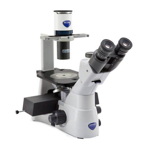
Optika XDS-3 User manual

XDS-3
OPERATION MANUAL
GUIDA UTENTE

Page 2
INDEX
1.0 WARNINGS page 4
2.0 COMPONENTS page 6
3.0 INSTALLATION page 7
4.0 ADJUSTING THE MICROSCOPE page 11
5.0 PHASE CONTRAST OPERATION page 15
6.0 MICROPHOTOGRAPHY AND VIDEO page 16
7.0 TECHNICAL SPECIFICATIONS page 17
8.0 TROUBLESHOOTING page 18
9.0 RECOVERY AND RECYCLING page 21

Page 3
This microscope is a scientic precision instrument designed to last for many years with a minimum of main-
tenance. It is built to high optical and mechanical standards and to withstand daily use.
Optika reminds you that this manual contains important information on safety and maintenance, and that it
must therefore be made accessible to the instrument users.
Optika declines any responsibility deriving from instrument uses that do not comply with this ma-nual.
Safety guidelines
This manual contains important information and warnings regarding safety about installation, use and
maintenance of the microscope. Please read this manual carefully before using the equipment. To
ensure safe use, the user must read and follow all instructions in this manual. OPTIKA products are
designed for safe use in normal operating conditions. The equipment and accessories described in
the manual are manufactured and tested according to industry standards for safety instrumentation
laboratory. Misuse can cause personal injury or damage to the instrument. Keep this manual at hand
close to the instrument, for an easy consultation.
Electrical safety
Before connecting the power cord to wall outlet, ensure that your mains voltage for your region corre-
sponds to the voltage supply of the instrument, and that the illuminator’s switch is in position OFF. The
user must observe the safety regulations in force in his region. The instrument is equipped with CE
safety marking, in any case the user has full responsibility concerning the safe use of that instrument.
Warning/Caution symbols used in this manual
The user should be aware of safety aspects when using the instrument. Warning or hazard symbols
are shown below. These symbols are used in this manual.
The instructions on this symbol to avoid possible severe personal injuries.
Warning of use; the incorrect operation on the instrument can cause damages to the
person or instrument.
Possibility of electric shock.
Attention: high temperature surfaces. Avoid direct contact.
Technical notes or usage tips.
SAFETY GUIDELINES

Page 4
1.0 WARNINGS
SAFETY NOTE
1 Do not store the instrument under direct sunlight, high
temperature or high humidity, nor in dusty environments.
Make sure the stage is plane, horizontal and stable.
2 When moving the microscope, please hold the instru-
ment with one hand on the lower side of the eyepiece
tube (1), and the other hand on the illumination bracket
(2) (Figure 1).
3 If water or bacterial cultures are spilled on the stage,
objective or viewing tube, pull out the power cord at
once, and wipe the microscope clean. Failing to do so
may result in damage to the instrument.
4 When working, the LED housing on the top of the arm
(3) (Figure 1) will become hot. Ensure good ventilation
around the LED housing.
5
The instrument must be connected to a grounded mains
supply.
6 Please use the supplied power cord only.
2
3
1
main switch
MAINTENANCE
1 Use a lint-free cloth to wipe the glass parts. In order to remove ngerprints and oil stains, slightly
dampen the cloth with xylene or with a 3:7 mixture of ethanol and ether.
► Note:ethanolandetherarehighlyammableliquids.Donotusethemnearaheatsource,
nearsparksornearelectricequipment.Usethesechemicalsinawellventilatedroom.
2 Do not use organic solvents to wipe the non-optical elements. Please use a neutral detergent
only.
3 During use, if liquids fall on the microscopes, cut off the power at once, and wipe up the moistu-
re.
4 Do not disassemble the microscope. Disassembling might degrade the performance of the mi-
croscope, and will invalidate the warranty.
5 When the objectives are not mounted, please cover the sockets with the dust caps, in order to
prevent dust and liquids from entering the microscope.
6 When not in use, remember to cover the microscope with the dust hood. Please let the lamp cool
down before covering the microscope.
Figure 1
Figure 2

Page 5
1.0 WARNINGS
SAFETY SYMBOLS
Symbol Meaning
The surface may be hot, do not touch.
Please read the instruction carefully, before use. Improper
operation will result in injuries or malfunction.
Main switch – ON position.
Main switch – OFF position.

Page 6
2.0 COMPONENTS
Objectives
- 10X (PH)
- 20X (PH)
- 40X
Phase contrast slider
LED housing
Illumination bracket
Condenser
Stage insert
Objective turret
(Nosepiece) (xed)
Stage (xed)
- Stage extension
- Glass stage
Microscope base
Trinocular viewing
tube (xed
Eyepieces

Page 7
3.0 INSTALLATION
3.1 INSTALLATION DIAGRAM
The following gure shows the installation sequence of the components.
The number in the gure shows the installation steps.
► Beforeinstalling,besureeverycomponentisclean.Takecarenottoscratchpartsor
surfaces.
► Storethesuppliedhexagonwrenchinasafeplace.Whenchangingthecomponents,
youwillneeditagain.
Microscope base
Mechanical stage
LED housing
Stage extension
Eyepiece
Glass stage Filter holder Objectives
1
Condenser
illumination
unit
2
3
4
5
6
7
NotincludedinLTversion

Page 8
3.0 INSTALLATION
3
3
1
24
Figure 3
3.2 INSTALLATION STEPS
3-2-1 Installing the condenser illumination unit and the
LEDhousing(g.3)
1. Insert the condenser illumination unit (1) into the bracket,
according to gure .
2. Turn the condenser illumination unit clockwise about 90°,
with the “AS” mark of lter holder (3) facing forwards. Align
the screw of the condenser illumination unit and the hole of
the holder, then screw the bolt in the hole with the supplied
hexagon spanner.
3. Insert the connector plug (2) into the connector jack (4).
4. Push the LED housing gently into the holes of the illumina-
tion unit.
3-2-2Installingtheobjectivesg.4&g.5
1. Turning the coarse focusing knob (1) till the nosepiece rea-
ches to its lowest position.
► Forasafetransport,thenosepieceisplacedinthelo-
westpositionandthetensionadjustmentcollar(2)is
adjusted to the appropriate tension when the micro-
scopeleavesthefactory.
2. Screw the lowest magnication objective on to the turret
from the right side, then turn the turret clockwise.
Mount the other objectives in the same way, following the
sequence from low to high.
► Note:theobjectivescanalsobeinstalledthroughthe
stage opening.
► Clean the objectives regularly. In inverted microscopes,
the objectives are very sensitive to dust.
► To prevent dust and contamination from entering the mi-
croscope, cover all the unused holes with dust caps (3).
► When operating, use the low magnication objective (10X)
to search and focus the specimen, then switch to higher
magnications.
► When switching between objectives, slowly turn the nose-
piece until it clicks. The click means that the objective is in
the right position, in the center of the light path.
Figure 5
Figure 4
1
2

Page 9
3-2-3Installingthestageextensionandthemechanicalstage(g.6)
(NotincludedinLTversion)
The stage extension can be installed on either side of the stage to en-
large the working surface. The mechanical stage must be installed on
the side opposite the extension.
For right-handed operators, the mechanical stage is normally installed
on the right side.
1. Installing the stage extension: Screw the bolts (1) on to the extension,
then mount the extension from below the stage. Screw it to a rm t.
2. Installing the mechanical stage: As for the extension, the mechanical
stage is xed by two bolts under the stage.
3-2-4Installingthestageinsert(g.7)
1. When using the glass stage (1), make sure that the stage is horizontal.
2. Install the stage insert in the stage opening.
Turn the disk until the V-groove faces the user. This simplies objective
identication.
3-2-5Installingtheeyepieces(g.8)
1. Remove the cap of the eyepiece tubes (1).
2. Insert the eyepieces (2) into the tubes.
3-2-6Installingthecolorlters(g.9)
► Besurethecolorlterhascooleddowncompletelybeforeyou
changethem.Removethelterholder(1),theninstallthecolor
lters(2)youneed.
Mount the color lter at as shown in (3), verifying that they are not
tilted.
► Ifthecolorlteristiltedorotherwiseoutofplace(4),itmayfall.
The color lters can be stacked in the holder. This allows to install as
many lters as needed, as long as the whole thickness is less than 11
mm.
3.0 INSTALLATION
1
2
3
4
Figure 6
Figure 9
Figure 8
Figure 7
1
1
1
2
2
1
43

Page 10
3.0 INSTALLATION
3-2-7Connectingthepowercord(g.10,11&12)
► Donottensionorotherwisestressthepowercord.Ifbent,
thewiresmayeasilybreak.
1. Turn the main switch (1) to “O”(off) before connecting the power
cord.
2. Insert the plug into the power jack (2) of the microscope.
3. Plug the power cord (4) into the mains socket. Check for a safe
connection.
► Please use the supplied power cord. If lost or damaged,
pleaserefertoqualiedservice.
► Connect the power cord to a grounded (earthed) power
supply only.
3-2-8Replacingthefuse(g.10&11)
Before replacing the fuse, turn the main switch (1) to “O” (off)
and unplug the power cord. Rotate the fuse support (3) out of
the holder using a straight screwdriver. Insert a new fuse in the
support, then rotate the support back into the holder.
► Fuserating:seebackofthemicroscope.
Figure 10
Figure 11
1
2 3
Figure 12
54

Page 11
4.0 ADJUSTING THE MICROSCOPE
Dioptric
adjustment ring
Light path
selector lever
Tension
adjustment collar Coarse
focus knob
Fine focus knob
Phase
contrast slider
Phase centering bolt
Aperture diaphragm
adjustment lever
Color lter holder

Page 12
4.0 ADJUSTING THE MICROSCOPE
4-1 MICROSCOPE BASE
4-1-1TurningontheLED(g.13)
Connect the power, turn on the main switch (1).
4-1-2Adjustingthebrightness(g.13)
Turn the brightness adjustment knob (2) to increase and de-
crease the brightness.
4-1-3Adjustingthetension(g.14)
► Thecoarsefocusingknob(1)ispreadjustedtoatight
tensionuponleavingthefactory.
If the nosepiece drops down by itself, or the specimen de-
focuses while adjusting the ne focus knob (3), the coarse
focus knob is too loose. Turning the tension adjustment col-
lar (2) in the indicated direction tightens the coarse focus
tension (1). Rotate in the opposite direction to decrease the
tension.
4-2 STAGE
4-2-1Settingthespecimen(g.15&16)
► Forthebestimagequality,useasks,Petridishesand
slideswitha1.2mmthickness.
Using Φ35mm culture dishes:
You can place a Φ 35 mm culture dish on the stage by using
the standard center board (1) of the stage.
Using the mechanical stage:
1. When observing 96-well or 24-well micro-titration plates,
please fasten them directly with the stage clip (2).
2. When fastening other plates, please use the adaptor plates
supplied with the mechanical stage:
● Terasaki bracket (3) for Terasaki boards
● Culture dish bracket (4) for Φ 35 mm culture dishes
● Object slide bracket (5) for object slides and Φ 54 mm
culture dishes
3. Turning the X and Y knobs (6,7), move the specimen to
the required position. (Movement Range: 120 (width) × 78
(length) mm).
Figure 13
Figure 14
Figure 16
(NotincludedinLTversion)
Figure 15
1
1
2
12 3
2
6
7
4
5
3

Page 13
4.0 ADJUSTING THE MICROSCOPE
12
4-2-2Movingthespecimen
Move the specimen to the desired position by freehand or by tur
ning the knobs of the mechanical stage.
► Whenswitchingobjectives,takecarenottotouchtheadaptor
plateswiththeobjectives,astheirweightmaydamagethefront
lens.
4-3 VIEWING TUBE
4-3-1Dioptricadjustment(g.17)
1. Look into the right eyepiece with your right eye only, and focus on the
specimen.
2. Look into the left eyepiece with your left eye only. If the image is not
sharp, use the dioptric adjustment ring (1) to compensate.
►The adjustment range is ±5 diopter. The number indicated on
the adjustment ring graduation should correspond to the ope-
rator’s dioptric correction.
4-3-2Adjustingtheinterpupillarydistance(g.18)
Observing with both eyes, hold the two eyepiece prism assemblies.
Rotate them around their common axis until the elds of view coin-
cide.
► Thegraduationontheinterpupillarydistanceindicator(3),poin-
tedbythespot“.”(2)ontheeyepieceholder,showsthedistan-
cebetweentheoperator’seyes(g.17).
The range of the interpupillary distance is 48-75mm.
4-3-3Selectingthelightpath(g.19)
Pull the light path selector lever (1) sideways using your thumb,
selecting the light path you need.
Figure 17
Figure 18
Figure 19
1
Brightness Application
IN 100% Used for binocular obser-
vation
Binocular observation
OUT
20% Used for binocular observa-
tion, and 80% used for video or
photography
Binocular observation, television,
and micrography or video can be
operated simultaneously
3

Page 14
4.0 ADJUSTING THE MICROSCOPE
4-4 ILLUMINATION UNIT
4-4-1Usingcolorlters(g.20)
Selecting the appropriate color lters according your need.
You can stack a group of color lters in the lter holder, if you
ensure that they are level and that the whole thickness is less
than 11mm.
4-4-2Usingtheaperturediaphragm(g.21)
When in bright eld observation, the aperture diaphragm con-
trols the numerical aperture of the illumination system. When
the numerical aperture of the objective and the aperture of the
illumination system match, the highest resolution is achieved.
● To identify the aperture diaphragm, the eyepiece can be re-
moved or the centering telescope can be used. The aperture
diaphragm looks as in g. 21.
The aperture can be changed by moving the aperture
adjustment lever. ((1)is the image of the aperture diaphragm,
(2) is the edge of the objective).
● Generally, when observing a fully chromatic specimen,
you need to set the size of the condenser to 70-80% of the
aperture of the objective. When observing unstained samples
(e.g. bacteria), start from 70% and slowly turn the aperture
diaphragm lever clockwise.
Figure 20
Figure 21
70-
80%
30-
20%
1
2
70-80%
30-20%
Color lter Use
IF550 Single contrast color lter (green)
used for phase contrast microscopy
LBD Color temperature compensation color
lter blue
used for bright eld observation and
microphotography

Page 15
5.0 PHASE CONTRAST OPERATION
5-1 IDENTIFYING THE COMPONENTS
5-1-1Phasecontrastobjectives(g.22)
The magnications of the optional phase contrast objectives are:
10X and 20X. These objectives are marked “PH”.
Mount the objectives on the turret using the same procedures as the
standard objectives (3-2-2).
5-1-2Phasecontrastslider(g.23)
Adjustable phase slider.
● The light ring is pre-centered when the microscope leaves the facto-
ry. It should therefore need no further adjustment. If a recentering is
needed, it can be performed via the two side bolts.
● The 10X/20X light ring (1) must be used with the 10X,20X phase
contrast objectives, the 40X light ring (2) with the 40X and the ope-
ning (3) is used for bright eld.
5-2 SETUP AND USE
5-2-1Installingthephasecontrastslider(g.24)
1. Insert the slider into the illumination system, printed face up.
2. Pull the slider into the desired position, to the click stop.
3. When in phase contrast observation, keep the aperture diaphragm
adjustment lever on the “O” (open) position.
5-2-2Centeringthering(g.25)
► Usuallythisoperationisnotneeded.Ifnecessary,pleasepro-
ceedwiththefollowingsteps:
1. Place a specimen on the stage and focus it.
2. Take out the eyepiece from the tube without the dioptric adjustment,
and replace it with the centering telescope (CT).
3. Check that the phase ring and the objective correspond, and that
both are steadily set on a click stop.
4. Use the CT to focus on the light ring’s image (5) and the phase con-
trast ring’s image (2). If the light ring’s image is not sharp, adjust the
CT’s eyepiece until you can see a clear image of the light ring (2).
5. Adjust the bolts of the two centering holes in the phase contrast
slider using a screwdriver until the light ring center and the phase
contrast ring center coincide.
6. The 10X and the 20X phase contrast objectives use the same ring
on the phase contrast slider. The coincidence of the light ring center
and the phase contrast center must be veried with both objectives.
►Ifthelightringiscenteredincorrectly,thecontrastwillbeseve-
rely impaired.
► Thephaseringmayneedrecenteringduringandafterobserva-
tionofverythickspecimens.
► Thephaseringmayshowanapparentmisalignmentiftheco-
verglassisnotat.
Figure 22
Figure 23
12
3
Figure 24
1
2
Figure 25

Page 16
6-1VIDEOPORT(VIDEO)
6-1-1Selectingthelightpath(g.26)
1. To activate the video port, pull out the light path selector lever.
► Forobservationofdarkspecimens,rstfocus,thenpull
outthelever.
6-1-2Installingthevideoadapter(g.27)
1. Loosen the locking bolt (1) on the trinocular viewing tube, and
take out the dust cap (2).
2. Set up the video adapter on the camera according to its in-
structions.
3. Install the adapter into the tri-through port, and screw down
the bolt (1).
6-1-3Focus(g.27)
During a binocular observation at 20% brightness, look at the
image on the video imaging system, refocusing the adapter if
necessary.
6-2 MICROPHOTOGRAPHY
6-2-1 Selecting the light path
Set up the light path as in (6-1-1) and in (4-3-3).
6-2-2Installingthephotographyadapter(g.28)
1. Loosen the locking bolt (1) on the trinocular viewing tube, and
take out the dust cap (2).
2. Install the photography adapter into the tri-through port accor-
ding to its instructions, and screw down the locking bolt (1).
3. Attach the camera ring (if any) to the adapter.
4. Attach the camera to the ring.
● Warning: for some cameras (mainly reex) the ring is not in-
cluded with the microscope, and it should be supplied by the
user.
● For the photography of dark specimens, obscure the eyepie-
ces and the viewnder with a dark cloth in order to reduce
stray light.
● The camera magnication can be calculated as objective ma-
gnication × camera + lens magnication.
►When shooting with a SLR, the mirror movement may
causecameramovement.Pleaseliftthemirror,uselong
exposuretimesanduseanextensioncord.
6.0 MICROPHOTOGRAPHY AND VIDEO
Figure 26
2
Adapter
CCD
Video
1
2
Adapter
Camera head
Camera
Figure 27
1
1
Figure 28

Page 17
6.0 MICROPHOTOGRAPHY AND VIDEO
6-2-3 Focus
During a binocular observation at 20% brightness, look at the
image on the video imaging system, refocusing the adapter if
necessary.
7.0 TECHNICAL SPECIFICATIONS
7-1 MAIN SPECIFICATIONS
Illumination Light source type X-LED8 with white 8W LED; light intensity control using a knob on left side of the
frame.
Color temperature: 6300K
LED average life time approx. 50.000h
Voltage: 110/240Vac, 50/60Hz, 1A ; Fuse: T500mA 250V
Max power required: 13W
ObservationModes Brighteld, phase contrast
Focusing Coaxial coarse and ne focusing mechanism (graduated, 0.002mm) with upper stop, to prevent the
contact between objective and specimen.
Adjustable tension of coarse focusing knob.
Stage Fixed stage, dimensions 250x230 mm.
Mechanical stage mountable on the right side of the stage, X-Y translation range 114x81 mm, with
metallic interchangeable inserts for slides, Petri dishes, Terasaki, multi-Well plates, etc. [not included
in LT version].
Pair of side extensions to expand the surface of the stage.
Glass stage insert with hole for small dimension specimens.
Nosepiece Quintuple revolving nosepiece, rotation on ball bearings.
Head Trinocular observation head, inclined 45°.
Diopter adjustment on left eyepiece.
Interpupillary adjustment 55-75 mm.
Eyepieces Wide eld eyepieces WF10X/22 with eld number 22.
Objectives Innity corrected optical system IOS (Innity Optical System).
Plan-achromatic LWD objectives innity corrected, for thickness 1.2 mm, made by following objecti-
ves:
-) Plan-achromatic IOS LWD 10XPh, N.A. 0.25, W.D. 7.94 mm
-) Plan-achromatic IOS LWD 20XPh, N.A. 0.40, W.D. 7.66 mm
-) Plan-achromatic IOS LWD 40XPh, N.A. 0.60, W.D. 3.71 mm
All objectives are treated with an anti-fungus treatment.
Condenser LWD condenser, N.A. 0.30, working distance 72 mm.
The condenser can be removed to extend the working distance up to 150 mm.
Precentered slider with phase rings 10X/20X and 40X
Dimensions HEIGHT: 485 mm
WIDTH: 300 mm
DEPTH: 550 mm
WEIGHT: 9 kg
Accessories Hard case [not included in LT version], instruction manual and dust cover included.

Page 18
Under certain conditions, some no-fault factors will bring a reversible inuence to the instrument’s
performance. If this happens, please take proper measures according to the follow table. If you can’t
solve the trouble as indicated, please contact the sales department of our Company.
8.0 TROUBLESHOOTING
PROBLEM REASON SOLUTION
I. Optical section
1. The illumination is
open, but the eld of
view is dark.
The plug of the LED holder is not
connected to the illumination set
Connect them
The brightness is too low Adjust to a proper setting
Too many colour lters have
been stacked
Minimize the number of the lters
2. The edge of the eld
of view is vignetted or
the brightness is asym-
metric.
The nosepiece is not in the cor-
rect position
Turn the nosepiece to a click stop
The color lter is partially inser-
ted
Insert the lter to full depth
The phase contrast slider is not
in the proper position
Move the slider to a click stop
3. Dust and stains can
be seen in the eld of
view.
There are stains and dust on the
specimen
Clean the specimen
There are stains and dust on the
eyepiece
Clean the eyepiece
4. There is an apparent
double image.
The size of the aperture
diaphragm is too small
Open the aperture diaphragm
5. Poor image quality:
The image is not sharp
The contrast is not high
The details are not clear
The phase contrast is
low.
The nosepiece is not in the cen-
ter of the light path
Turn the nosepiece to a click stop
The aperture diaphragm in the
view of eld is opened too much
or too little
Adjust the aperture diaphragm
The lenses (condenser, objecti-
ve, eyepieces are culture dish)
is dirty
Thoroughly clean all the optical system
In phase contrast observation,
the bottom thickness of the sam-
ple is more than 1.2mm
Use a sample holder whose bottom thick-
ness is less than 1.2mm
A bright eld objective is used for
phase contrast observation
Switch to a phase contrast objective
The condenser ring is not ali-
gned with the objective phase
ring
Adjust the condenser ring to match the
objective phase ring
The light ring and/or the phase
contrast ring is not centered
Adjust the bolts to center them
The objective used is not compa-
tible with the phase ring
Please use a compatible objective
The phase contrast depends on
the sample position
The sample holder is not at. Move the
sample around until a compatible area is
found.

Page 19
8.0 TROUBLESHOOTING
6. One side of the image
is out of focus.
The nosepiece is not in the cen-
ter of the light path
Turn the nosepiece to a click stop
The specimen is out of place
(tilted)
Place the specimen at on the stage.
The optical performance of the
sample cover glass is poor
Use a cover glass of better quality
II. Mechanical section
1.The coarse focus knob
is hard to turn.
The tension adjustment collar is
too tight
Loosen the tension adjustment collar
2.The focus is unstable. The tension adjustment collar is
too loose
Tighten the tension adjustment collar
III. Electric section
1. The LED doesn’t turn
on.
No power supply Check the power cord connection
2. The brightness is not
enought
The brightness adjustment is low Adjust the brightness
3. The light blinks The power cord is poorly con-
nected
Check the power cord
IV.Viewingtubeassembly
The eld of view of the
two eyes is different.
The interpupillar distance is not
correct
Adjust the interpupillar distance
The dioptric correction is not
right
Adjust the dioptric correction
The viewing technique is not cor-
rect, and the operator is straining
the eyesight
When look into the objective, do not stare at
the specimen but look at the whole eld of
view. Periodically, move the eyes away to
look at a distant object, then back into the
objective
V.Microphotographyandvideo
1. The image is unfocu-
sed.
Incorrect focusing Adjusting the focus system as in the present
manual
2. The edge of the image
is unfocused.
To some degree, it is inherent to
the nature of achromatic objec-
tives
The problem can be minimized by a correct
setting of the aperture diaphragm
3. Bright patches appear
on the image.
Stray light is entering the micro-
scope through the eyepieces
and through the camera viewn-
der
Cover the eyepieces and the viewnder with
a dark cloth

Page 20
9.0 RECOVERY AND RECYCLING
Art.13 Dlsg 25 july 2005 N°151. “According to directives 2002/95/EC, 2002/96/EC and 2003/108/EC relating
to the reduction in the use of hazardous substances in electrical and electronic equipment and waste dispo-
sal.”
The basket symbol on equipment or on its box indicates that the product at the end of its useful life should be
collected separately from other waste.
The separate collection of this equipment at the end of its lifetime is organized and managed by the
producer. The user will have to contact the manufacturer and follow the rules that he adopted for
end-of-life equipment collection. The collection of the equipment for recycling, treatment and en-
vironmentally compatible disposal, helps to prevent possible adverse effects on the environment
and health and promotes reuse and/or recycling of materials of the equipment. Improper dispo-
sal of the product involves the application of administrative penalties as provided by the laws in force.
Table of contents
Languages:
Other Optika Microscope manuals

Optika
Optika B-383LD1 User manual

Optika
Optika IM-2 User manual

Optika
Optika SZN Series User manual

Optika
Optika B-1000 POL User manual

Optika
Optika B-500Ti-2 User manual

Optika
Optika B-810 Series User manual

Optika
Optika LAB-1 User manual

Optika
Optika B-380 Series User manual

Optika
Optika IM-3MET User manual

Optika
Optika B-510 Series User manual

Optika
Optika XZ-2 User manual

Optika
Optika B-190 User manual

Optika
Optika B-190 User manual

Optika
Optika B-50 User manual

Optika
Optika SZM User manual

Optika
Optika B-500DK User manual

Optika
Optika IM Series User manual

Optika
Optika B-1000 MET User manual

Optika
Optika B-500 User manual

Optika
Optika B-380 Series User manual