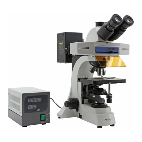
Optika XDS-3FL User manual

OPERATION MANUAL
XDS-3FL

Page 2
CONTENTS
SAFETY GUIDELINES.............................................................................................page 3
BEFORE USE...........................................................................................................page 4
1.0 NOMENCLATURE .............................................................................................page 6
2.0 ASSEMBLING ...................................................................................................page 7
2.1 Assemble scheme ................................................................................page 7
2.2 Assemble steps ....................................................................................page 8
3.0 OPERATION .....................................................................................................page 11
3.1 Illumination ...........................................................................................page 13
3.2 Filter preventing board ........................................................................page 13
3.3 Centering bulb ......................................................................................page 14
3.4Viewelddiaphragm...........................................................................page15
3.5Selectourescencelterblock..........................................................page15
4.0 GENERAL SPECIFICATION ............................................................................page 16
5.0TROUBLESHOOTING.......................................................................................page 17
6.0 RECYCLING AND RECOVERY.........................................................................page 19

Page 3
This microscope is a scientic precision instrument designed to last for many years with a minimum of main-
tenance. It is built to high optical and mechanical standards and to withstand daily use.
Optika reminds you that this manual contains important information on safety and maintenance, and that it
must therefore be made accessible to the instrument users.
Optika declines any responsibility deriving from instrument uses that do not comply with this ma-nual.
Safety guidelines
This manual contains important information and warnings regarding safety about installation, use and
maintenance of the microscope. Please read this manual carefully before using the equipment. To
ensure safe use, the user must read and follow all instructions in this manual. OPTIKA products are
designed for safe use in normal operating conditions. The equipment and accessories described in
the manual are manufactured and tested according to industry standards for safety instrumentation
laboratory. Misuse can cause personal injury or damage to the instrument. Keep this manual at hand
close to the instrument, for an easy consultation.
Electrical safety
Before connecting the power cord to wall outlet, ensure that your mains voltage for your region corre-
sponds to the voltage supply of the instrument, and that the illuminator’s switch is in position OFF. The
user must observe the safety regulations in force in his region. The instrument is equipped with CE sa-
fety marking, in any case the user has full responsibility concerning the safe use of that instrument.
Warning/Caution symbols used in this manual
The user should be aware of safety aspects when using the instrument. Warning or hazard symbols
are shown below. These symbols are used in this manual.
The instructions on this symbol to avoid possible severe personal injuries.
Warning of use; the incorrect operation on the instrument can cause damages
to the person or instrument.
Possibility of electric shock.
Attention: high temperature surfaces. Avoid direct contact.
Technical notes or usage tips.
SAFETY GUIDELINES

Page 4
BEFORE USE
1. Notice:
(1) As the microscope is a precision instrument, a lways operate it
with care, avoiding physical shake during the operation.
(2) Do not let the microscope emerge in the sun directly, either not in
the high temperature, damp, dusty or acute shake place. Make sure
the worktable is horizontal. Following environment is required: Indoor
temperature: 5°C~40°C, Max relative humidity:80%.
(3) When moving the microscope, you should use both hands to hold
1 and 2 as shown on gure, and lay it down carefully. (Figure 1)
(4) Fluorescence microscope should be used under dark entironment.
(5) In order to protect eyes, do not stare at uorescence light directly.
(6) The bulb should be vertical under using, the inclined angle should
be less than 15 degrees, otherwise it will make bulb damage.
(7) Fluorescence sample will be faded by ultraviolet radiation, so it
can not for long save. Do not expose the sample under uorescence
light for long time, it will be quenched.
(8) When working, the surface of the lamp holder 3 and bulb house
4 will be very hot. Make sure there is enough space (especially its
above) for the heat dissipating. (Fig. 1)
(9) Connect the microscope to the land to avoid lightning strike.
(10) Make sure the switch 5, 6 are at “○” position, cut off power supply
and wait all parts cool down before replace bulbs, fuse the fuse. It
would be better to do so after cooling the bulb and the lamp holder.
(Fig. 2, 3)
Inverted uorescence microscope specially suit for research work for activity cell, tissue,
uidness and sediment, especially for biology, cytology, oncology, genetics and immunology
etc. It is wildly used in Lab, university, medical, epidemic prevention and so on.
Connectthemainsplugintothesocketatthebase
Make sure, before you turn the illumination on, that the voltage selector is set to the mains voltage for
your region.
The power cord should be used only on network sockets equipped with adequate grounding.
Contact a technician to check the state of your electrical system. If there is no need to install additional
accessories, the instrument is now ready for use. Once positioned and installed with the necessary
components, the microscope is ready to be used. Your microscope is a laboratory instrument desi-
gned to last. Handle it always carefully and avoid abrupt vibrations or shocks. Always disconnect the
power cable from the microscope when not in use for long time, while you clean it or when you perform
any maintenance.
AVOIDDISASSEMBLINGTHEINSTRUMENT
Do not disassemble the instrument. This entails the cancellation of the warranty and may cause
malfunction.
Page 5
BEFORE USE
-Standard bulb:
Fluorescence light: 100W mercury bulb Transmitted light: 6V30W halogen bulb (Philips)
(11) Power supply: 90-240V wildly
(12) Please use the plug provide our company.
2. Maintenance
(1) Wipe the lens gently with a soft lens tissue. Carefully wipe off oil or ngerprints on the lens surfaces with
tissue moistened with a little of 3:7 mixture of alcohol and ether or dimethy lbenzene.
-Alcohol and ether is ammable. Don’t place these chemical near to re or re source. For example, when
turning on or turning off the electric device, you should use these chemical in a ventilated place.
(2) Don’t use organic solution to wipe the surfaces of the other components. Please use the neutral
detergent.
(3) If the microscope damped by the liquid, you should cut off the power immediately and wipe it dry.
(4) Never disassemble or service the microscope yourself. It will inuence its function or damage it.
(5) After using, cover the microscope with a dust cover.
3. Safety Sign

Page 6
1.0 NOMENCLATURE

Page 7
2.0 ASSEMBLING
2.1 Assembling scheme:
Numbers denote the assembling order.
-Beforeassembling,makesurethereisnodustordirt.Assemblecarefullyanddonotscrap
any part or touch the glass face.
-During assembling, please be aware of no scratching and no touching on lenses.

Page 8
2.0 ASSEMBLING
-Beforeassemblingforuorescenceparts,please
setpowersupplyat“OFF”andtakeofftheplugin
order to operator’s safety.
2-2-2Settheuorescenceblocks
(1) Loose the lock-screw 1 with M4 inner hexagon spanner
and take off right cover 2 (Fig. 4)
(2) Match the dovetail glut of lter block B1 3 to the groove
of sliding channel 4, and push 3 into sliding channel
4 at right.
(3) Put on the right cover 2, point the screw 1 to the hole
5 on sliding channel 4 and tight it with M4 spanner.
(4) Insert the pole 7 into the hole 6 on right cover 2, and
point it to the hole at side of lter block B1 3, then tight.
(Fig.5)
(5) Loose the screw cap 9 a little, and turn the remark block
8 to make the letter “B” point to operator, then tight 9.
- XDS-3FL uorescence microscope can only be
equipped
with2pcslterblocks.ThestandardisB1andG1.
Others for selection.
-UsethesamewaytosetlterblockG1totheleft.
- Please be aware the remark (such as: DMB1) on the
side
should be correctly, do not overturn with up and down.
- During observation, both right and left cover can’t be
takenoffbecauseitprotectsthelterwhilelter
exchanging.
2-2-2Settheuorescenceconnector
(1) Hook the hole 1 to take off the uorescence hole cover
2. (Fig. 6)
(2) Insert the uorescence connector 3 to the uorescence
hole
to make the screw 4 point to thread 5, and tight 3 screws
with M4 spanner. (Fig.7)
(3) Turn off one of handles 7 from uorescence preventing
board 8 and insert the board 8 into connector, you will
nd sound to mean it at middle position (there are 3
positions). And tight the handle 7. (Fig. 8)
2.2 Assembling steps:

Page 9
2-2-3 Set light source with mercury bulb
(1) Loose screw 1 with M4 inner hexagon spanner. (Fig.9)
(2) Insert the light source with mercury bulb 2 into
uorescence connector 3, and rotate 2 to make its upper
plane 4 as horizontal, then tight the screw 1 with M4
spanner.
-Duringobservation,pleasemakesureenoughspacefor
heat-reekaroundthebulbsource,especiallytheupper
and bottom of bulb.
-Duringobservation,pleasemakesureenoughdistance
between light source and power plug to avoid power
plug melted by heat on light source.
2-2-4 Set mercury bulb
(1) Loose the lock-screw 1 completely by M4 inner hexagon
spanner, rotate about 45 degrees as the direction showed,
and take off the bulb holder 2. (Fig. 10)
(2) Loose the lock screw 3 for mercury bulb and take off the
supporting pole 4. Insert the anode side (big side) on
mercury bulb into the anode holder 6 and set negative
holder on small side of bulb, then tight the screw 3. (Fig.11)
-Pleasemakesurethemercurybulbputvertically.If
thereisaspiratingholeonbulb,pleasemakesurethe
hole directly to ceramic holder.
(3) Put the bulb holder 2 into its house and tight the screw 1.
- It is the same way to replace bulb.
- Replace bulb during or after operation:
During or just after operation, the bulb, bulb house
and around is very hot. Before replace the bulb, please
setthepowersupplyforuorescenceat“o”(OFF)and
takeoffthepowerplug.Afterallcoolingdownto
replace bulb.
- After replace bulb, please be aware the timer on powers
upply at zero. See details “3-1”
2.0 ASSEMBLING

Page 10
2-2-5Connectpowersupply
(1) Make sure that the main power supply and
uorescence
power supply at “o” (OFF).
(2) Connect one side the plug 1 to the connector 2 on
light
source with mercury bulb and lock the screo. (Fig. 12)
(3) Use same way to connect other side of the plug 1
to
connector 3 uorescence power supply.
(4) Connect one side of the plug 4 to socket 5 on
uorescence power supply and other side to power
supply socket.
-Theuorescencepowersupplyis110-240V.
- Please curve and enlace the plug wire softly to
avoid
damage it.
- Please use the standard plug wire provide our
company. Select suitable one when missing or
damagment.
- Connect the power supply correctly, be sure the
instrument earth-connecting.
2-2-6 Replace fuse
Before replace fuse, please set the main power supply
and uorescence power supply at “o” (OFF) and take
off plug.
Use “_” screw driver to take off fuse set 1 from holder 2
and change a new one. (Fig. 13)
-Fusespecication:250V,3.15A
2-2-7 Set eye-protecting board
(1) Loose screw 1 till enough to put in trinocular cover.
(Fig.14)
(2) Set the holder 2 close with trinocular cover 3 and
horizontal the eye-protecting board, then tight the screw
1.
(3) Loose the screw 4 a little to let connecting pole 5
moving as showed direction. And adjust the
eye-protecting board to suitable position, then tight the
screw 4.
2.0 ASSEMBLING

Page 11
3.0 OPERATION

Page 12
3.0 OPERATION

Page 13
While using transmitted illumination, the operation way is the same as inverted biological microscope.
Below is the operation way under reected uorescence illumination.
3-1 Illumination
(1) After connect with main power supply, please
set the switch 1 on uorescence power supply at “_”
(ON), then the indicator light. It costs 5 minutes to
warm up mercury bulb. (Fig. 16)
(2) Use adjusting knob for electric current 6 to make
out-put power as same as mercury bulb 100W.
Min. scale for ammeter 5 is 0.4A and Max. is 2A.
Min. scale for voltmeter 7 is 0.4A and Max. is 2A.
- No need to switch on for transmitted
illumination
whenusinguorescenceillumination.
- When use mercury bulb for rst time or just
replace
bulb, please set the timer reset 3 to highest
position
as till timer 4 indicates “000.00”, then set 3 to
lowest position.
-Donotcutoffpowersupplywithin15minutes
after
mercury bulb light on to avoid it damaged.
- In order to prolong the life of mercury bulb,
please do
not re-light on it within 3 minutes after it turned
off.
- When the timer 4 indicates “200.00”, it means
the
mercury bulb had lighted on for 200 hours and it
is its
utmost and it is time for replacement.
-Don’tstareatuorescencelightdirectly.
3-2Uselterpreventingboard
Pull the lter preventing board 1 to the most left
position,it prevents fluorescence light while middle
position for light. If set 32 filter in the right groove
on board 1 and pull it to most right position for light
ltration.
-Whennoneedobservationunderuorescence
light, please pull the lter preventing board
to most left position to protect the slide from
uorescencequenchingbylongtimeexposure.
3.0 OPERATION

Page 14
3-3 Centering mercury bulb
(1) Turn the nosepiece 1 to make blank hole into
light-path. Take off nosepiece cap when it has.
(Fig.18)
Figure 18
(2) Pull lter exchanging pole 3 to the middle position
for B1 observation.
(3) Turn adjusting pole 3 for view eld diaphragm
by clock-wise to make the view eld to largest. (Fig.
18).
(4) Set a white paper on stage and pull lter preventing
board 4 to middle position for observation.
(5) Adjust focusing lock-knob 5, vertical adjusting
screw 7 for mercury bulb, horizontal adjusting screw
6 for mercury bulb to make the bulb image on white
paper. (Fig.18, 19, 20a)
(6) Adjust focusing screw 9 for reecting lens,
horizontal centering screw 8 for reecting mirror,
vertical centering screw 10 for reecting lens to
make the bulb reected image on white paper. (Fig.
19, 20b)
(7) Adjust screw 8 and 10 to make the bulb image
and bulb reected imagte symmetry. Adjust screw
10 to make
both images with same size. (Fig. 19, 20c)
(8) Adjust screw 6 to make the two images
superposition. (Fig. 19, 20a)
(9) Turn 10X objective into light-path and set slide
on stage for observation under B1. Find the image
and make it clear.
(10) Observe through eyepieces and adjust focusing
lock-knob 5 to make view eld to best, then lock the
knob.
- Centering the bulb after it warmed up will be
more
precision.
- Adjust the vertical and horizontal screw for
bulb
image,thereectedimagewillalsobemoved.
- After replace the mercury bulb, it should be
re-center
the bulb.
3.0 OPERATION

Page 15
3-4Viewelddiaphragm
Field diaphragm limits the light beam diameter into
condenser, therefore eliminates the surround light in
order to enhance image contrast. When eld diaphragm
image is just at edge of eld, objective can provide best
performance and the image is clearest.
(1) Turn adjusting pole 1 for view eld diaphragm
clock-wisely to open the view eld diaphragm, otherwise
to close. (Fig. 21)
(2) Observe through eyepiece to nd image of view
eld diaphragm.
(3) Adjust two screws 2 at both side of view eld
diaphragm to center the image.
(4) Open the eld diaphragm gradually. If the image
of eld diaphragm is just inscribed to the view eld,
it means the eld diaphragm had been centered.
(Fig.22)
(5) While actual operation, please open the eld
diaphragm a little to make it ex-scribed with view eld
in order to obtain better image.
-Inordertopreventthespecimenfromuorescence
quenching, don’t expose the same position of the
specimen for long time.
3-5Fluorescencelterblock
The lter block should be accordance with specimen.
Please
see the parameters “Sheet 1” for spectrum.
Standard lter block: B1, G1
(1) Pull the lter preventing board 2 to the most right position. (Fig.3)
(2) Use lter exchanging pole 1 to select needed lter block.
-Whenusingtransmittedillumination,pleasepullbothB1,G1lterblockstomostleftand
right position.
3.0 OPERATION

Page 16
4.0 GENERAL SPECIFICATION
Typology INVERTED RESEARCH MICROSCOPE
Description Laboratory inverted microscope for research applications.
Dye-cast frame, with high stability and ergonomy, for transmitted light and and
reected uorescence observation.
Illumination Transmitted Light:
Light source type X-LED8 with white 8W LED; light intensity control using a knob
on left side of the frame.
Color temperature: 6300K
LED average life time approx. 50.000h
Voltage: 110/240Vac, 50/60Hz, 1A ; Fuse: T500mA 250V
Max power required: 13W
ReectedLight:
Mercury burner 100W HBO, light control based on external power supply.
Bulb average life time approx. 300 hours.
Voltage: 10/240Vac, 50/60Hz, 1A ; Fuse: F8AL 250V.
Max power required: 125W
Observation Modes Brighteld, phase contrast, Fluorescence B and G
Fluorescence B: EX 460-490, DM 500, EM 520LP;
Fluorescence G: EX 480-550, DM 570, EM 590LP;
Fluorescence UV (optional): EX 325-375, DM 400, EM 420LP;
Fluorescence V (optional): EX 385-425, DM 440, EM 455LP.
Fluorochromes Excitation B: Acridine Yellow, Acridine Orange, Auramine, DiO, DTAF, FITC, GFP,
YFP, ecc.
Excitation G: DiL; Blu Evans, Feulgen, Rhodamine, Texas Red, TRITC, PI, ecc.
Excitation UV (optional):
AMCA, AutoFluorescence, BAO, BFP, Blu Cascade, DANS, DAPI, Hoechst, Indo-
1, SITA, ecc.
Excitation V (optional): ANS, Fluorescamine, Catecholamine, ecc.
Focusing Coaxial coarse and ne focusing mechanism (graduated, 0.002mm) with upper
stop, to prevent the contact between objective and specimen. Adjustable tension of
coarse focusing knob.
Stage Fixed stage, dimensions 250x230 mm.
Mechanical stage mountable on the right side of the stage, X-Y translation range
114x81 mm, with metallic interchangeable inserts for slides, Petri dishes, Terasaki,
multi-Well plates, etc.
Pair of side extensions to expand the surface of the stage.
Glass stage insert with hole for small dimension specimens.
Nosepiece Quintuple revolving nosepiece, rotation on ball bearings.
Head Trinocular observation head, inclined 45°.
Diopter adjustment on left eyepiece.
Interpupillary adjustment 55-75 mm.
Eyepieces Wide eld eyepieces EWF10X/22 with eld number 22.
Objectives Innity corrected optical system IOS (Innity Optical System).
Plan-achromatic LWD objectives innity corrected, for thickness 1.2 mm, made by
following objectives:
-) Plan-achromatic IOS FLUO LWD 10X, N.A. 0.30, W.D. 10.0 mm
-) Plan-achromatic IOS FLUO LWD 20X, N.A. 0.45, W.D. 5.1 mm
-) Plan-achromatic IOS FLUO LWD 40X, N.A. 0.65, W.D. 2.6 mm
All objectives are treated with an anti-fungus treatment.

Page 17
4.0 GENERAL SPECIFICATION
Condenser LWD condenser, N.A. 0.30, working distance 72 mm.
The condenser can be removed to extend the working distance up to 150 mm.
Dimensions HEIGHT: 485 mm
WIDTH: 300 mm
DEPTH: 600 mm
WEIGHT: 10 kg
Accessories Interferential lter IF550, blu lter LBD. Instruction manual and dust cover inclu-
ded.
SYMPTOM CAUSE REMEDY
1. OPTICS
(1) THE LAMP IS NOT
BRIGHT ENOUGH
VIEW FIELD DIAPHRAGM IS NOT LAR-
GE ENOUGHT
OPEN THE DIAPHRAGM MORE
FILTER BLOCKS ARE NOT AT COR-
RECT POSITION
ADJUST THEM
(2) IMAGE BLUR THE OBJECTIVE IS NOT
UNDER LIGHT
TURN THE NOSEPIECE TO LOCK POSI-
TION
DIRT ON LENS CLEAN IT
FIELD DIAPHRAGM IS TOO LARGE OR
NARROW
ADJUST IT
THE FILTER BLOCK IS NOT
ACCORDANCE WITH
SPECIMEN
ADJUST FILTER BLOCK
(3) BLUR FIELD OR
BRIGHTNESS
ASYMMETRY
NOSEPIECE IS NOT AT LOCK POSI-
TION
TURN THE NOSEPIECE TO LOCK POSI-
TION
FILTER BLOCKS ARE NOT AT COR-
RECT POSITION
ADJUST THEM
BULB IS NOT CENTERED CENTER THE BULB
CONDENSER ADJUSTING KNOB IS
NOT AT CORRECT POSITION
ADJUST IT
FIELD DIAPHRAGM IS NOT CENTE-
RED
ADJUST IT
5.0TROUBLESHOOTING

Page 18
5.0TROUBLESHOOTING
2. ELECTRICS
(1) INDICATOR ON
FLUORESCENCE
POWER SUPPLY IS NOT
LIT
NO POWER SUPPLY CHECK THE CONNECTION OF POWER
SUPPLY
THE FUSE IS BURNT OUT REPLACE FUSE
(2) INDICATOR ON
FLUORESCENCE
POWER SUPPLY LIGHT,
BUT BULB IS NOT LIGHT
INCORRECT CONNECTION OF POWER
SUPPLY
CHECK THE CONNECTION
DESTRUCTION OF POWER PLUG CHANGE A NEW ONE
THE MERCURY BULB BURNT OUT REPLACE BULB
(3) MERCURY BULB
FLASHES
THE POWER SUPPLY HAS JUST BEEN
CONNECTED
WAIT THE BULB WARM UP
INCORRECT CONNECTION OF POWER
SUPPLY
CHECK THE CONNECTION
THE MERCURY BULB WILL BE BURNT
OUT SOON
REPLACE BULB

Page 19
6.0 RECYCLING AND RECOVERY
Art.13 Dlsg 25 july 2005 N°151. “According to directives 2002/95/EC, 2002/96/EC and 2003/108/EC relating
to the reduction in the use of hazardous substances in electrical and electronic equipment and waste dispo-
sal.”
The basket symbol on equipment or on its box indicates that the product at the end of its useful life should be
collected separately from other waste.
The separate collection of this equipment at the end of its lifetime is organized and managed by
the producer. The user will have to contact the manufacturer and follow the rules that he adop-
ted for end-of-life equipment collection. The collection of the equipment for recycling, treatment
and environmentally compatible disposal, helps to prevent possible adverse effects on the environ-
ment and health and promotes reuse and/or recycling of materials of the equipment. Improper dispo-
sal of the product involves the application of administrative penalties as provided by the laws in force.

www.optikamicroscopes.com
info@optikamicroscopes.com
OPTIKA
S.R.L.
Via Rigla 30, Ponteranica (BG) -
ITALY
Tel.: ++39 035 571392 (6 linee) Telefax: ++ 39 035
571435
MAD Iberica Aparatos
Cientificos
c/. Puig i Pidemunt, nº 28 1º 2ª - (Pol. Ind. Plà d’en Boet) 08302 MATARO
(Barcelona) España Tel: +34 937.586.245 +34 937.414.529
New York Microscope Company Inc
100 Lauman Lane, Suite A, Hicksville, New York 11801, USA
Tel.: 877.877.7274 - Fax: 516.801.2046
www.microscopeinternational.com -
info@nyscopes.com
OPTIKA MICROSCOPES -
ITALY
www.optikamicroscopes.com -
info@optikamicroscopes.com
Table of contents
Other Optika Microscope manuals

Optika
Optika XC-100L User manual

Optika
Optika ECOVISION M-100FL User manual

Optika
Optika B-800 User manual

Optika
Optika B-1000 POL User manual

Optika
Optika B-600 MET User manual

Optika
Optika B-190 User manual

Optika
Optika SZM User manual

Optika
Optika B-180 User manual

Optika
Optika B-380 Series User manual

Optika
Optika B-1000 Series User manual

Optika
Optika IM Series User manual

Optika
Optika OPTIGEM User manual

Optika
Optika B-190 User manual

Optika
Optika B-150POL-M User manual

Optika
Optika B-190 User manual

Optika
Optika B-1000 MET User manual

Optika
Optika B-810 Series User manual

Optika
Optika B-500Ti-2 User manual

Optika
Optika LAB User manual

Optika
Optika B-1000 POL User manual