manuals.online logo
Brands
  1. Home
  2. •
  3. Brands
  4. •
  5. Orbis
  6. •
  7. Thermostat
  8. •
  9. Orbis LIV-A User manual

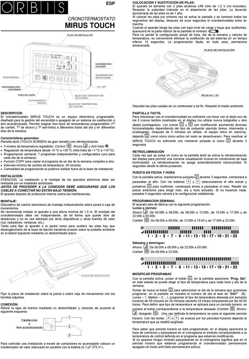
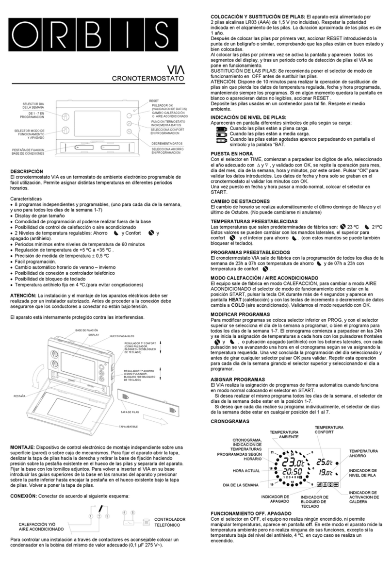
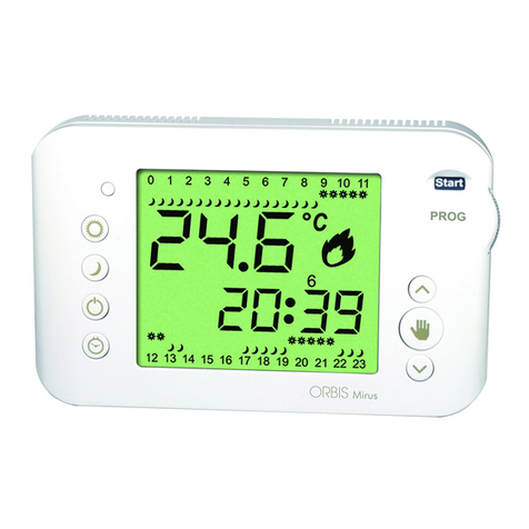
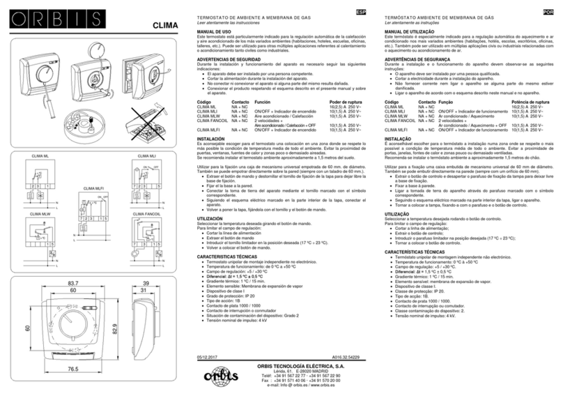
Orbis LIV-A User manual

ORBIS TECNOLOGÍA ELÉCTRICA, S.A.
Lérida, 61 E–28020 MADRID
Teléfono:+ 34 91 5672277; Fax:+34 91 5714006
E-mail: info@ orbis.es
htt
p
://www.orbis.es
ORBIS ITALIA S.p.A.
Via L. Da Vinci, 9/B 20060 Cassina De’ Pecchi - MI
Tel. 02/95343454 Fax 02/9520046
e-mail: [email protected]
htt
p
://www.orbisitalia.it
ADVERTENCIAS DE SEGURIDAD
Para asegurar el nivel de seguridad establecido por el dispositivo es
necesario respetar las siguientes reglas:
1) El instrumento debe ser instalado por persona especializada
2) Seguir escrupulosamente los diagramas de conexión para instalar el
instrumento
3) Antes de acceder a los bornes de conexión controlar que los conductores
por conectar o bien ya conectados al instrumento no estén bajo tensión
4) No suministrar corriente o conectar el instrumento si alguna parte del
mismo está dañada
CARACTERÍSTICAS TÉCNICAS
sAlimentación: 230 V AC (+10%/-15%) 50/60Hz
sAbsorción: máx. 6 VA - 1 W
sRelé de intervención monoestable con contacto en intercambio
sCapacidad de corte de 8(5)A/250 V AC
sAlcance de regulación de la temperatura: +5 °C ÷ +30 °C
sDiferencial fijo en 0,3 °C con regulación tipo ON/OFF
sProporcional con diferencial de 0.8 °C y base tiempos de 8 minutos
con regulación de tipo proporcional 8
sProporcional con diferencial de 1,5 °C y base tiempos de 15 minutos
con regulación de tipo proporcional 15
sTemperatura de trabajo: 0 °C ÷ +50 °C
sTemperatura di almacenamiento: -10 °C ÷ +60 °C
sHumedad relativa: 20%÷90% no condensante
sContenedor: material policarbonato color blanco
sNivel de protección: IP40
NOTA
A) Dimensiones
B) Diagramas de conexión
C) Modos de funcionamiento
D) Montaje
INSTALACIÓN Y MONTAJE
sEs necesario montar el termostato ambiente a una altura de aprox. 150 cm del piso,
en paredes internas, resguardado de la radiación solar directa y de cualquier fuente
térmica como lámparas, tubos de calefacción, etc.
sEs posible efectuar la instalación en pared o en caja empotrada de 3 módulos.
Los tornillos para la sujeción del tablero de bornes se entregan con el instrumento
(figura D)
CONEXIÓN ELÉCTRICA
sAtenerse al diagrama de conexión presente en el instrumento o bien observar
la figura B.
sSelección del modo de funcionamiento (figura B1):
- Lengüeta conectada en posición 1-2: funcionamiento ON/OFF
- Lengüeta conectada en posición 2-3: funcionamiento proporcional 8
- Lengüeta conectada en posición 3-4: funcionamiento proporcional 15
sEl encendido del led verde “1”- (figura C) indica la presencia de la alimentación.
AJUSTE TEMPERATURAS
sActuar en el botón de regulación de la temperatura.
Hasta que el led rojo “2” - (figura C) permanece encendido la temperatura
ajustada es superior a la temperatura medio-ambiental.
sPara proteger la duración de la instalación el tiempo mínimo de conmutación
del relé corresponde a 1 minuto.
sEs posible obtener un bajón de la temperatura ajustada de 3 °C con el cierre
de un contacto externo conectado según lo representado en la figura B (ON -3 °C)
Nota: en caso de daños de la sonda o del dispositivo de regulación, el
contacto del relé se abre y el led rojo intermitente señala una condición
de alarma
NORMAS DE REFERENCIA
La conformidad con las Disposiciones Comunitarias:
73/23/CEE mod. por 93/68/CEE (Baja Tensión)
89/336/CEE mod. por 92/31/CEE / 93/68/CEE (E.M.C.)
se declara con respecto a las siguientes Normas:
en cuanto a Seguridad: EN 60730-2-9
en cuanto a Compatibilidad electromagnética: EN 55014-1 y EN 55014-2
Manual de Uso
TERMOSTATO ELECTRÓNICO DE PARED
Leer atentamente todas las instrucciones
AVVERTENZE DI SICUREZZA
Per garantire il grado di sicurezza previsto dal dispositivo occorre
attenersi alle seguenti prescrizioni:
1) Il prodotto deve essere installato da persona competente
2) Seguire scrupolosamente gli schemi di collegamento per installare
lo strumento
3) Prima di accedere ai morsetti di collegamento assicurarsi che i conduttori
da collegare o già collegati allo strumento non siano in tensione
4) Non alimentare o collegare il prodotto se qualche parte di esso risulta
danneggiata
CARATTERISTICHE TECNICHE
sAlimentazione: 230 V AC (+10%/-15%) 50/60Hz
sAssorbimento: max 6 VA - 1 W
sRelè di intervento monostabile con contatto in scambio
sPotere di interruzione di 8(5)A/250 V AC
sCampo di regolazione della temperatura: +5 °C ÷ +30 °C
sDifferenziale fisso a 0,3 °C con regolazione di tipo ON/OFF
sProporzionale con differenziale di 0.8 °C e base tempi di 8 minuti
con regolazione di tipo proporzionale 8
sProporzionale con differenziale di 1,5 °C e base tempi di 15 minuti
con regolazione di tipo proporzionale 15
sTemperatura di funzionamento: 0 °C ÷ +50 °C
sTemperatura di immagazzinamento: -10 °C ÷ +60 °C
sUmidità relativa: 20%÷90% non condensante
sContenitore: materiale policarbonato di colore bianco
sGrado di protezione: IP40
LEGENDA
A) Dimensioni
B) Schemi di collegamento
C) Modi di funzionamento
D) Montaggio
INSTALLAZIONE E MONTAGGIO
sIl termostato ambiente deve essere montato ad un'altezza di circa 150 cm dal
pavimento, su pareti interne, al riparo dall'irraggiamento solare diretto e da
qualunque fonte termica come lampade, tubi di riscaldamento, ecc.
sÈ possibile l'installazione da parete o su scatola da incasso 3 moduli.
Le viti per il fissaggio della basetta sono in dotazione allo strumento. (fig. D)
COLLEGAMENTO ELETTRICO
sOsservare lo schema di collegamento che si trova all'interno dello strumento
o vedere la fig. B.
sSelezione della modalità di funzionamento (fig. B1):
- Cavaliere allacciato in posizione 1-2: funzionamento ON/OFF
- Cavaliere allacciato in posizione 2-3: funzionamento proporzionale 8
- Cavaliere allacciato in posizione 3-4: funzionamento proporzionale 15
sL'accensione del led verde “1”- (fig. C) indica la presenza dell'alimentazione.
IMPOSTAZIONE TEMPERATURE
sAgire sulla manopola di regolazione della temperatura.
Finché il led rosso “2” - (fig. C) rimane acceso la temperatura impostata
è superiore alla temperatura ambiente.
sPer salvaguardare la vita dell'impianto Il tempo minimo di commutazione del relè
è di 1 minuto.
sÈ possibile ottenere un’abbassamento della temperatura impostata di 3 °C con la
chiusura di un contatto esterno collegato come in fig.B (ON -3 °C)
Nota: nel caso di danneggiamento della sonda o del dispositivo di
regolazione, viene aperto il contatto del relè e viene segnalata una
condizione di allarme tramite intermittenza del led rosso
NORME DI RIFERIMENTO
La conformità alle Direttive Comunitarie:
73/23/CEE mod. da 93/68/CEE (Bassa Tensione)
89/336/CEE mod. da 92/31/CEE a 93/68/CEE (E.M.C.)
è dichiarata in riferimento alle Norme seguenti:
Sicurezza: CEI-EN 60730-2-9
Compatibilità elettromagnetica: CEI-EN 55014-1 e CEI-EN 55014-2
Manuale d’Uso
TERMOSTATO ELETTRONICO DA PARETE
Leggere attentamente tutte le istruzioni
Mod. LIV-A
448-010
20 25
30
15
10
5
1 2 3 4
ON/OFF
123 4
Prop. 8
1 2 34
Prop. 15
1 2 3 4
ON/OFF
123 4
Prop. 8
1 2 34
Prop. 15
(A)
20 25
30
15
10
5
115
(B)
ON
-3 °C
NL
(C)
(D)
92
32
1
2
B1
Uscita relé
Relay output
Salida relé
Saída relé
8(5) A/250 V~
Manual de Utilização
TERMÓSTATO ELECTRÓNICO MURAL
Ler atentamente as instruções
ADVERTÊNCIAS DE SEGURANÇA
■Para garantir o nível de segurança estabelecido pelo dispositivo devem observar-se as
seguintes instruções:
1) O aparelho deve ser instalado por uma pessoa qualificada
2) Respeitar escrupulosamente os diagramas de ligação para instalar o aparelho
3) Antes de aceder aos bornes de ligação, assegurar-se de que os condutores a ligar ou já
ligados ao aparelho não estão sob tensão
4) Não fornecer corrente ou ligar o aparelho se alguma parte do mesmo estiver danificada
CARACTERÍSTICAS TÉCNICAS
• Alimentação: 230 V AC (+10%/-15%) 50/60 Hz
• Absorção máx. 6 VA - 1 W
• Relé de intervenção monoestável com contacto em comutação
• Capacidade de corte de 8(5)A/250 V AC
• Intervalo de regulação da temperatura: +5 °C ÷ +30 °C
• Diferencial fixo em 0,3 °C com regulação do tipo ON/OFF
• Proporcional com diferencial de 0.8 °C e com base em períodos de 8 minutos com
regulação de tipo proporcional 8
• Proporcional com diferencial de 1,5 °C e com base em períodos de 15 minutos com
regulação de tipo proporcional 15
• Temperatura de funcionamento: 0 °C ÷ +50 °C
• Temperatura de armazenamento: -10 °C ÷ +60 °C
• Humidade relativa: 20%÷90% não condensada
• Contentor: policarbonato branco
• Classe de protecção: IP 40
NOTA
A) Dimensões
B) Diagramas de ligação
C) Modos de funcionamento
D) Montagem
INSTALAÇÃO E MONTAGEM
• É necessário montar o termóstato ambiente a uma altura de aproximadamente 1,50 m
do chão, em paredes internas, protegido da radiação solar directa e de qualquer fonte
térmica como candeeiros, condutas de aquecimento, etc.
• É possível efectuar a instalação mural ou em caixa embutida de 3 módulos. Os
parafusos para a fixação do painel de bornes são fornecidos com o aparelho (figura D)
LIGAÇÃO ELÉCTRICA
• Respeitar o diagrama de ligação descrito no aparelho ou então observar a figura B.
• Selecção do modo de funcionamento (figura B1):
– Patilha na posição 1-2: funcionamento ON/OFF;
– Patilha na posição 2-3: funcionamento proporcional 8;
– Patilha na posição 3-4: funcionamento proporcional 15;
• O led verde iluminado “1”- (figura C) indica a presença de alimentação eléctrica
REGULAÇÃO DAS TEMPERATURAS
• Manusear o botão de regulação da temperatura. Enquanto o led vermelho “2” -
(figura C) permanecer iluminado, a temperatura configurada é superior à temperatura
ambiente.
• Para proteger a durabilidade da instalação, o tempo mínimo de comutação do relé
corresponde a 1 minuto.
• E’ possível conseguir uma descida da temperatura configurada em 3 °C com o
encerramento de um contacto externo ligado de acordo com o representado na figura B
(ON -3 °C)
Nota: em caso de danos na sonda ou no dispositivo de regulação, o contacto
do relé abre-se e o led vermelho intermitente indica uma situação de
advertência
NORMAS DE REFERÊNCIA
■A conformidade com as Directrizes Comunitárias:
73/23/CEE modificada pela 93/68/CEE (Baixa Tensão)
89/336/CEE modificada pela 92/31/CEE / 93/68/CEE (EMC)
é declarada em relação às seguintes Normas:
■Segurança: EN 60730-2-9
■Compatibilidade electromagnética: EN 55014-1 e EN 55014-2
Axxx.xx.xxxxx
SAFETY WARNINGS
To guarantee the level of safety built into the device, please observe the
following instructions:
1) The product should be installed by a skilled operator
2) Carefully follow the connection diagrams to install the instrument
3) Before touching the connector terminals, make sure the wires to be
connected to the instrument are not live
4) Do not power or connect the product if any part of it is damaged
TECHNICAL SPECIFICATIONS
sPower supply: 230 V AC (+10%/-15%) 50/60Hz
sAbsorption: max 6 VA - 1 W
sSingle stable intervention relay with exchange contact
sSwitching power: 8(5)A/250 V AC
sTemperature regulation field: +5 °C ÷ +30 °C
sFixed differential at 0.3 °C with ON/OFF regulation
sProportional with differential of 0.8 °C and base time 8 minutes
with 8 proportional regulation
sProportional with differential of 1.5 °C and base time 15 minutes
with 15 proportional regulation
sOperating temperature: 0 °C ÷ +50 °C
sStorage temperature: -10 °C ÷ +60 °C
sRelative humidity: 20%÷90% non-condensing
sContainer: white polycarbonate material
sProtection level: IP40
LEGEND
A) Dimensions
B) Connection diagrams
C) Operating modes
D) Assembly
INSTALLATION AND ASSEMBLY
sThe ambient thermostat should be mounted at a height of roughly 150 cm from the
floor, and kept out of direct sunlight and all heat sources, such as lights, heating pipes
and similar.
sThe product may be wall-mounted or fitted in a 3-module built-in box.
The fixing screws for the base are supplied with the instrument (fig. D).
ELECTRICAL CONNECTION
sFollow the connection diagram inside the instrument or see fig. B
sSelecting the operating mode (fig. B1):
- Marker connected in position 1-2: ON/OFF operation
- Marker connected in position 2-3: 8 proportional operation
- Marker connected in position 3-4: 15 proportional operation
sThe green power on warning light “1” - (fig. C) will come on.
SETTING THE TEMPERATURES
sAdjust the temperature regulation knob.
When red warning light “2” is on (fig. C), the temperature set is higher than the
ambient temperature.
sTo ensure the long life of the system, the minimum relay switching time is 1 minute.
sIt is possible to obtain a lowering of the temperature set by 3 °C with the closure
of an outside contact connected as shown in fig.B (ON -3 °C)
Note: in the event of damage to the probe or regulation device, the relay
contact is opened and an alarm condition is indicated by the flashing of the
red warning light.
REFERENCE STANDARDS
Conformity with EU directives:
73/23/EEC, modified by 93/68/EEC (low voltage)
89/336/EEC, modified by 92/31/EEC and 93/68/EEC (E.M.C.)
is declared with reference to the following standards:
Safety: EN 60730-2-9
Electromagnetic compatibility: EN 55014-1 and EN 55014-2
User's Manual
WALL-MOUNTED ELECTRONIC THERMOSTAT
Read all the instructions carefully
ORBIS TECNOLOGÍA ELÉCTRICA, S.A.
Lérida, 61 E–28020 MADRID
Teléfono:+ 34 91 5672277; Fax:+34 91 5714006
E-mail: info@ orbis.es
htt
p
://www.orbis.es
ORBIS ITALIA S.p.A.
Via L. Da Vinci, 9/B 20060 Cassina De’ Pecchi - MI
Tel. 02/95343454 Fax 02/9520046
e-mail: [email protected]
htt
p
://www.orbisitalia.it
ADVERTENCIAS DE SEGURIDAD
Para asegurar el nivel de seguridad establecido por el dispositivo es
necesario respetar las siguientes reglas:
1) El instrumento debe ser instalado por persona especializada
2) Seguir escrupulosamente los diagramas de conexión para instalar
el instrumento
3) Antes de acceder a los bornes de conexión controlar que los conductores
por conectar o bien ya conectados al instrumento no estén bajo tensión
4) No suministrar corriente o conectar el instrumento si alguna parte del
mismo está dañada
CARACTERÍSTICAS TÉCNICAS
sAlimentación: 2 baterías alcalinas micro (AAA) de 1,5 V
sAutonomía: 12 meses aproximadamente
sRelé de intervención biestable con contacto en intercambio (inversor)
sCapacidad de corte de 8(5)A / 250 V AC
sAlcance de regulación de la temperatura: +5 °C ÷ +30 °C
sDiferencial fijo en 0,5 °C
sRegulación de la temperatura tipo ON/OFF
sTemperatura de trabajo: 0 °C ÷ +50 °C
sTemperatura di almacenamiento: -10 °C ÷ +60 °C
sHumedad relativa: 20%÷90% no condensante
sContenedor: material policarbonato color blanco
sNivel de protección: IP40
NOTA
A) Dimensiones
B) Diagramas de conexión
C) Modos de funcionamiento
D) Montaje
INSTALACIÓN Y MONTAJE
sEs necesario montar el termostato ambiente a una altura de aprox. 150 cm del
piso, en paredes internas, resguardado de la radiación solar directa y de cualquier
fuente térmica como lámparas, tubos de calefacción, etc.
sEs posible efectuar la instalación en pared o en caja empotrada de 3 módulos.
Los tornillos para la sujeción del tablero de bornes se suministran con el instrumento
(figura D)
sPara la introducción o la sustitución de las baterías extraer hacia arriba la específica
caja (figura C).
sIntroducir sólo baterías alcalinas respetando las polaridades como indicado
en la parte interna de la misma caja.
sControl del estado de carga de las baterías (figura C):
- interruptor pulsado “Batería Test” y LED “1” encendido: batería cargada
- interruptor pulsado “Batería Test” y LED “1” apagado: batería descargada
CONEXIÓN ELÉCTRICA
sAtenerse al diagrama de conexión presente en el instrumento o bien observar
la figura B.
AJUSTE TEMPERATURAS
sEl instrumento se entrega con el interruptor en la posición “”(calefacción)
sObrar en el botón de regulación de la temperatura girándolo hasta el disparo del relé
para controlar la capacidad de funcionamiento del sistema.
Ajustar mediante el mismo botón la temperatura deseada
sLa posición “NOCHE ” del interruptor frontal determina el bajón de
la temperatura ajustada de 3 °C.
NORMAS DE REFERENCIA
La conformidad con las Disposiciones Comunitarias:
73/23/CEE mod. por 93/68/CEE (Baja Tensión)
89/336/CEE mod. por 92/31/CEE / 93/68/CEE (E.M.C.)
se declara con respecto a las siguientes Normas:
en cuanto a Seguridad: EN 60730-2-9
en cuanto a Compatibilidad electromagnética: EN 55014-1 yEN 55014-2
Manual de Uso
TERMOSTATO ELECTRÓNICO DE PARED
Leer atentamente todas las instrucciones
AVVERTENZE DI SICUREZZA
Per garantire il grado di sicurezza previsto dal dispositivo occorre
attenersi alle seguenti prescrizioni:
1) Il prodotto deve essere installato da persona competente
2) Seguire scrupolosamente gli schemi di collegamento per installare lo
strumento
3) Prima di accedere ai morsetti di collegamento assicurarsi che i conduttori
da collegare o già collegati allo strumento non siano in tensione
4) Non alimentare o collegare il prodotto se qualche parte di esso risulta
danneggiata
CARATTERISTICHE TECNICHE
sAlimentazione: 2 batterie alcaline micro stilo (AAA) da 1,5 V
sAutonomia: 12 mesi circa
sRelè di intervento bistabile con contatto in scambio (invertitore)
sPotere di interruzione di 8(5)A / 250 V AC
sCampo di regolazione della temperatura +5 °C ÷ +30 °C
sDifferenziale fisso a 0,5 °C
sRegolazione della temperatura di tipo ON/OFF
sTemperatura di funzionamento: 0 °C ÷ +50 °C
sTemperatura di immagazzinamento: -10 °C ÷ +60 °C
sUmidità relativa: 20% ÷ 90% non condensante
sContenitore: materiale policarbonato di colore bianco
sGrado di protezione: IP40
LEGENDA
A) Dimensioni
B) Schemi di collegamento
C) Modi di funzionamento
D) Montaggio
INSTALLAZIONE E MONTAGGIO
sIl termostato ambiente deve essere montato ad una altezza di circa 150 cm
dal pavimento, su pareti interne, al riparo dall'irraggiamento solare diretto e da
qualunque fonte termica come lampade, tubi di riscaldamento, ecc.
sÈ possibile l'installazione da parete o su scatola da incasso 3 moduli.
Le viti per il fissaggio della basetta sono in dotazione allo strumento. (fig. D)
sPer l'inserimento o la sostituzione delle batterie estrarre verso l'alto l'apposito
cassetto (fig. C).
sInserire solo batterie di tipo alcalino ponendo attenzione a rispettare le polarità,
come indicato nella parte interna dello stesso cassetto.
sControllo dello stato di carica delle batterie (fig. C):
- pulsante premuto “Battery Test” e LED “1” acceso: batteria carica
- pulsante premuto “Battery Test” e LED “1” spento: batteria scarica
COLLEGAMENTO ELETTRICO
sOsservare lo schema di collegamento che si trova all'interno dello strumento
o vedere la fig. B
IMPOSTAZIONE TEMPERATURE
sLo strumento viene fornito con l'interruttore nella posizione “”(riscaldamento)
sAgire sulla manopola di regolazione della temperatura ruotandola fino al momento
dello scatto del relè per controllare la funzionalità del sistema. Impostare tramite
la stessa manopola la temperatura desiderata.
sLa posizione “NOTTE ” dell'interruttore frontale comporta l'abbassamento
della temperatura impostata di 3 °C.
NORME DI RIFERIMENTO
La conformità alle Direttive Comunitarie:
73/23/CEE mod. da 93/68/CEE (Bassa Tensione)
89/336/CEE mod. da 92/31/CEE a93/68/CEE (E.M.C.)
è dichiarata in riferimento alle Norme seguenti:
Sicurezza: CEI EN 60730-2-9
Compatibilità elettromagnetica: CEI EN 55014-1 eCEI EN 55014-2
Manuale d’Uso
TERMOSTATO ELETTRONICO DA PARETE
Leggere attentamente tutte le istruzioni
Mod. LIV DN-B
449-010
(A)
115
20 25
30
15
10
5
(B)
92
32
Uscita relé
Relay output
Salida relé
Saída relé
8(5) A/250 V~
20 25
30
15
10
5
(C)
1
Battery
Test
(D)
Manual de Utilização
TERMÓSTATO ELECTRÓNICO MURAL
Ler atentamente as instruções
ADVERTÊNCIAS DE SEGURANÇA
■Para garantir o nível de segurança estabelecido pelo dispositivo devem observar-se as
seguintes instruções:
1) O aparelho deve ser instalado por uma pessoa qualificada.
2) Respeitar escrupulosamente os diagramas de ligação para instalar o aparelho.
3) Antes de aceder aos bornes de ligação, assegurar-se de que os condutores a ligar ou já
ligados ao aparelho não estão sob tensão.
4) Não fornecer corrente ou ligar o aparelho se alguma parte do mesmo estiver danificada
CARACTERÍSTICAS TÉCNICAS
• Alimentação: 2 pilhas alcalinas (AAA) de 1,5 V
• Autonomia: aproximadamente 1 ano
• Relé de intervenção biestável com contacto em comutação (inversor)
• Capacidade de corte de 8(5)A/250 V AC
• Intervalo de regulação da temperatura: +5 °C ÷ +30 °C
• Diferencial fixo em 0,5 °C
• Regulação de temperatura do tipo ON/OFF
• Temperatura de funcionamento: 0 °C ÷ +50 °C
• Temperatura de armazenamento: -10 °C ÷ +60 °C
• Humidade relativa: 20%÷90% não condensada
• Contentor: policarbonato branco
• Classe de protecção: IP 40
NOTA
A) Dimensões
B) Diagramas de ligação
C) Modos de funcionamento
D) Montagem
INSTALAÇÃO E MONTAGEM
• É necessário montar o termóstato ambiente a uma altura de aproximadamente 1,50 m
do chão, em paredes internas, protegido da radiação solar directa e de qualquer fonte
térmica como candeeiros, condutas de aquecimento, etc.
• É possível efectuar a instalação mural ou em caixa embutida de 3 módulos. Os
parafusos para a fixação do painel de bornes são fornecidos com o aparelho (figura D)
• Para a introdução ou substituição das pilhas, puxar para cima a tampa do compartimento das
pilhas
(figura C)
.
• Introduzir apenas pilhas alcalinas, respeitando as polaridades indicadas no interior da caixa.
• Controlo do estado de carga das pilhas
(figura C)
:
– Interruptor premido
“Teste das Pilhas”
t
Led
“1”
iluminado: pilhas com carga.
– Interruptor premido
“Teste das Pilhas”
t
Led
“1”
apagado: pilhas esgotadas
LIGAÇÃO ELÉCTRICA
• Respeitar o diagrama de ligação descrito no aparelho ou então observar a figura B.
REGULAÇÃO DAS TEMPERATURAS
• O aparelho é fornecido com o interruptor na posição “ ” (aquecimento).
• Rodar o botão de regulação da temperatura até activar o relé.
• Para controlar a capacidade de funcionamento do sistema, configurar com o mesmo
botão a temperatura desejada:
–
A posição “NOITE ” do interruptor determina a diminuição da temperatura
configurada em 3 °C;
NORMAS DE REFERÊNCIA
■A conformidade com as Directrizes Comunitárias:
73/23/CEE modificada pela 93/68/CEE (Baixa Tensão)
89/336/CEE modificada pela 92/31/CEE / 93/68/CEE (EMC)
é declarada em relação às seguintes Normas:
■Segurança: EN 60730-2-9
■Compatibilidade electromagnética: EN 55014-1 e EN 55014-2
A016.70.54055
SAFETY WARNINGS
To guarantee the level of safety built into the device, please observe the
following instructions:
1) The product should be installed by a skilled operator
2) Carefully follow the connection diagrams to install the instrument
3) Before touching the connector terminals, make sure the wires to be
connected to the instrument are not live
4) Do not power or connect the product if any part of it is damaged
TECHNICAL SPECIFICATIONS
sPower supply: 2x1.5 V micro-stylus alkaline batteries (AAA)
sAutonomy: 12 months approximately
sBi-stable intervention relay with exchange contact (inverter)
sSwitching power: 8(5)A / 250 V AC
sTemperature regulation field: +5 °C ÷ +30 °C
sFixed differential at 0.5 °C
sON/OFF temperature regulation
sOperating temperature: 0 °C ÷ +50 °C
sStorage temperature: -10 °C ÷ +60 °C
sRelative humidity: 20%÷90% non-condensing
sContainer: white polycarbonate material
sProtection level: IP40
LEGEND
A) Dimensions
B) Connection diagrams
C) Operating modes
D) Assembly
INSTALLATION AND ASSEMBLY
sThe ambient thermostat should be mounted at a height of roughly 150 cm from
the floor, and kept out of direct sunlight and all heat sources, such as lights, heating
pipes and similar.
sThe product may be wall-mounted or fitted in a 3-module built-in box.
The fixing screws for the base are supplied with the instrument (fig. D).
sTo insert or replace the batteries, pull out the compartment in the upward
direction (fig. C)
sUse only alkaline batteries and ensure the polarity is correct, as indicated inside the
compartment
sChecking the battery charge condition (fig. C):
- with “Battery Test” button held down and warning
light “1” ON: battery charged
- with “Battery Test” button held down and warning
light “1” OFF: battery discharged
ELECTRICAL CONNECTION
sFollow the connection diagram inside the instrument or fig. B
SETTING THE TEMPERATURES
sThe instrument is supplied with the switch in position “”(heating)
sAdjust the temperature regulation knob by turning it until the relay clicks in to check
the operation of the system. Use the same knob to set the temperature as required.
sThe “NIGHT ” position of the front panel switch causes the lowering
of the temperature set by 3 °C.
REFERENCE STANDARDS
Conformity with EU directives:
73/23/EEC, modified by 93/68/EEC (low voltage)
89/336/EEC, modified by 92/31/EEC and 93/68/EEC (E.M.C.)
is declared with reference to the following standards:
Safety: EN 60730-2-9
Electromagnetic compatibility: EN 55014-1 and EN 55014-2
User Manual
WALL-MOUNTED ELECTRONIC THERMOSTAT
Read all the instructions carefully

Other Orbis Thermostat manuals

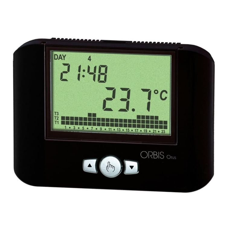
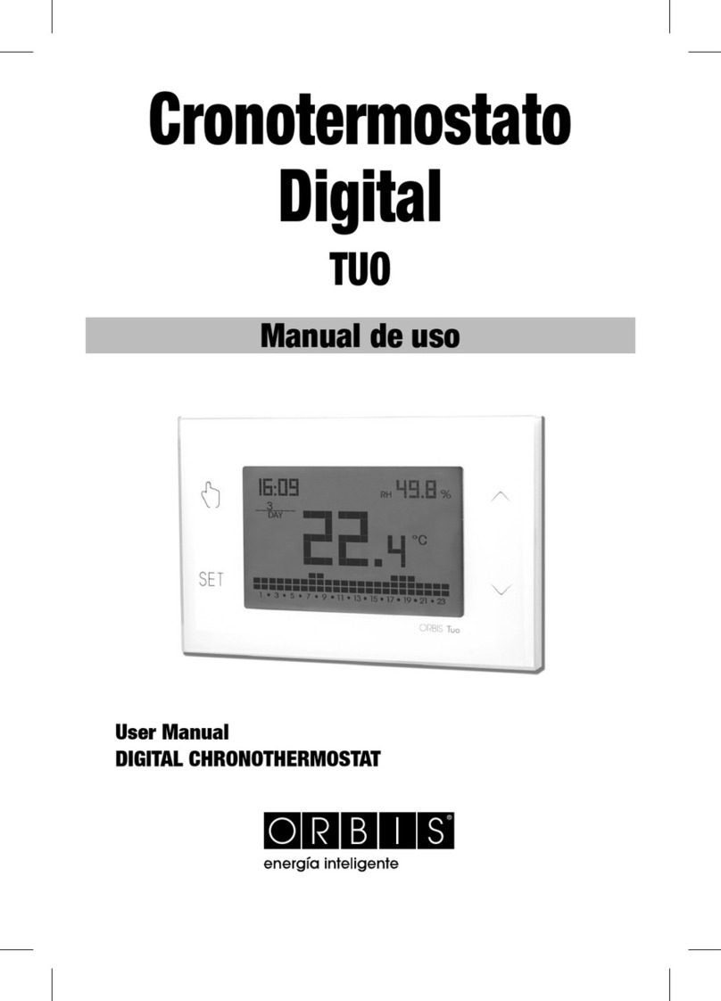
Orbis TUO User manual

Orbis

Orbis TUO User manual

Orbis Thermo X User manual

Orbis

Orbis Thermo X User manual

Orbis Era User manual

Orbis

Orbis Era User manual

Orbis MIRUS User manual

Orbis

Orbis MIRUS User manual

Orbis CLIMA Series User manual

Orbis

Orbis CLIMA Series User manual

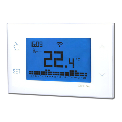
Orbis Tuo Wi-Fi User manual

Orbis

Orbis Tuo Wi-Fi User manual

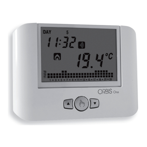
Orbis ORUS User manual

Orbis

Orbis ORUS User manual

Orbis TEK User manual

Orbis

Orbis TEK User manual

Orbis NEXU User manual

Orbis

Orbis NEXU User manual

Orbis MIRUS TOUCH User manual

Orbis

Orbis MIRUS TOUCH User manual

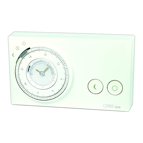
Orbis Lyra User manual

Orbis

Orbis Lyra User manual

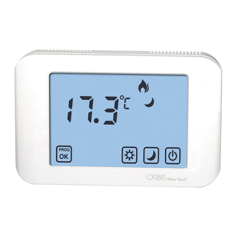
Orbis VELUS TOUCH User manual

Orbis

Orbis VELUS TOUCH User manual

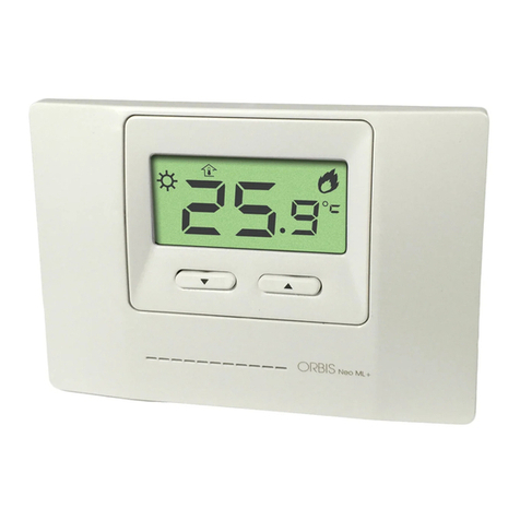
Orbis NEO ML+ User manual

Orbis

Orbis NEO ML+ User manual

Orbis CHRONOS User manual

Orbis

Orbis CHRONOS User manual

Orbis VIA User manual

Orbis

Orbis VIA User manual

Orbis SCL250 User manual

Orbis

Orbis SCL250 User manual

Orbis ORUS RF User manual

Orbis

Orbis ORUS RF User manual

Orbis Tuo Wi-Fi Pila User manual

Orbis

Orbis Tuo Wi-Fi Pila User manual

Popular Thermostat manuals by other brands

Aube Technologies TH232-AF-230 installation instructions

Aube Technologies

Aube Technologies TH232-AF-230 installation instructions

jablotron TP-60 manual

jablotron

jablotron TP-60 manual

ENDA EDT3423A quick start guide

ENDA

ENDA EDT3423A quick start guide

Danfoss RET2001 user guide

Danfoss

Danfoss RET2001 user guide

Honeywell CT3400 instructions

Honeywell

Honeywell CT3400 instructions

Sunricher SR-ZG9092A quick start guide

Sunricher

Sunricher SR-ZG9092A quick start guide

CLIMASET D Series quick start guide

CLIMASET

CLIMASET D Series quick start guide

ICM Controls SC 4811 Installation, operation & application guide

ICM Controls

ICM Controls SC 4811 Installation, operation & application guide

Jackson Systems Comfort System T-32-P installation manual

Jackson Systems

Jackson Systems Comfort System T-32-P installation manual

Derale 16720 installation instructions

Derale

Derale 16720 installation instructions

CAME BPT TH/500 Installation and use manual

CAME BPT

CAME BPT TH/500 Installation and use manual

Schluter Systems DITRA-HEAT-E-R quick start guide

Schluter Systems

Schluter Systems DITRA-HEAT-E-R quick start guide

Pentair Raychem SENZ quick start guide

Pentair

Pentair Raychem SENZ quick start guide

Carrier 33CS operating guide

Carrier

Carrier 33CS operating guide

EPH HDT Installation and operation guide

EPH

EPH HDT Installation and operation guide

VDH PROBA 5 Compact installation manual

VDH

VDH PROBA 5 Compact installation manual

Johnson Controls TCN-890x installation instructions

Johnson Controls

Johnson Controls TCN-890x installation instructions

Casals CTRL-MAX User and programming manual

Casals

Casals CTRL-MAX User and programming manual

manuals.online logo
manuals.online logoBrands
  • About & Mission
  • Contact us
  • Privacy Policy
  • Terms and Conditions

Copyright 2025 Manuals.Online. All Rights Reserved.