oventrop 168 07 06 User manual
Other oventrop Control Unit manuals

oventrop
oventrop Oilstop V User manual
oventrop
oventrop Regufloor HN User manual
oventrop
oventrop Cocon 2TZ User manual
oventrop
oventrop HR Series User manual

oventrop
oventrop AQH User manual
oventrop
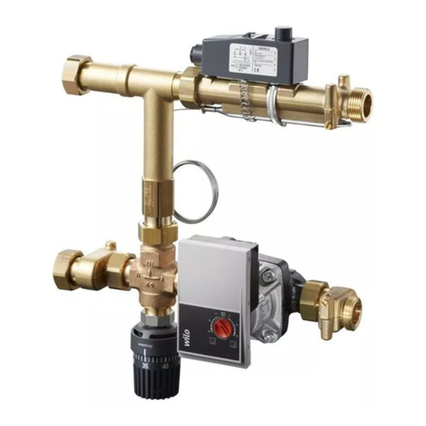
oventrop AQH User manual
oventrop
oventrop Regufloor H Operating instructions

oventrop
oventrop Regufloor HW User manual
oventrop
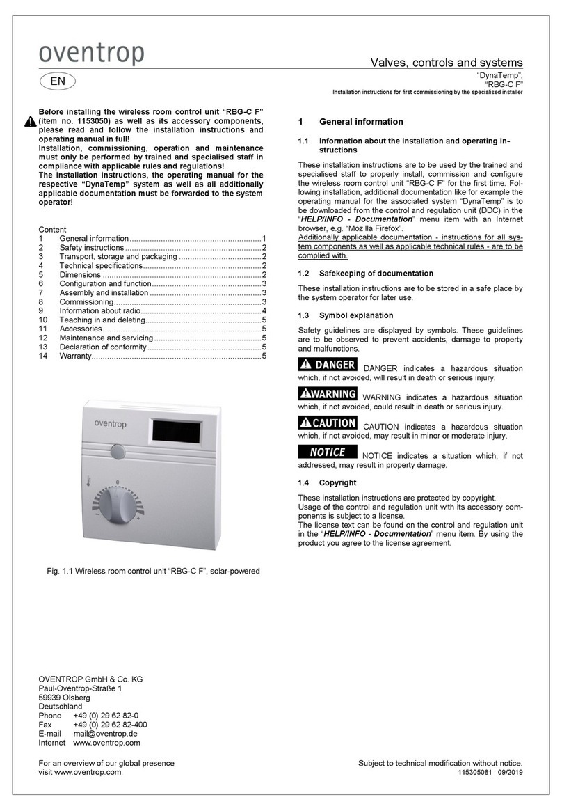
oventrop DynaTemp RBG-C F User manual
oventrop
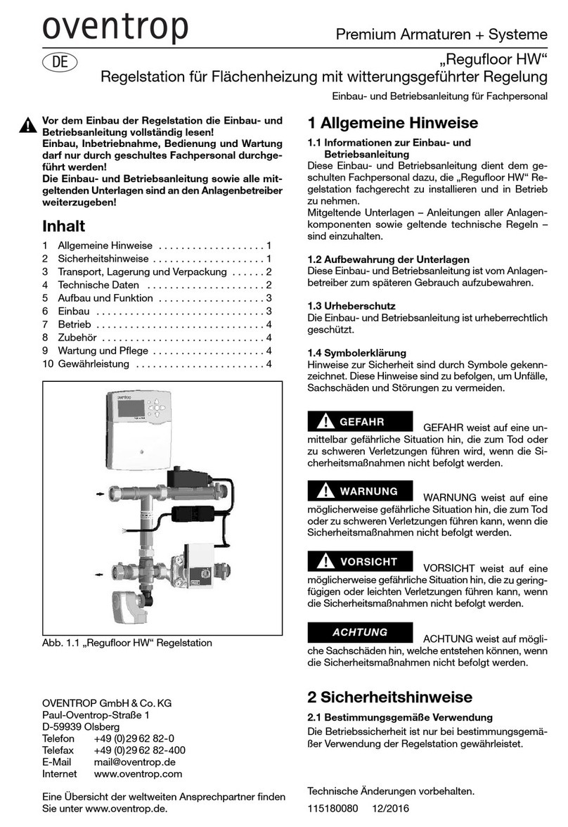
oventrop Regufloor HW Operating instructions
oventrop
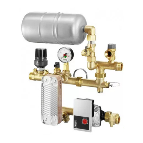
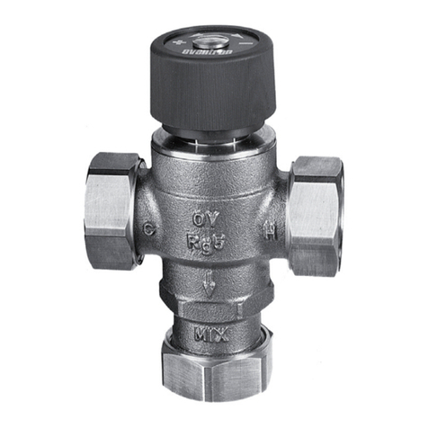
oventrop Regufloor HX Operating instructions
oventrop
oventrop Brawa-Mix User manual

oventrop
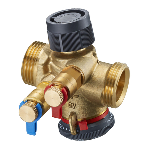
oventrop 1022668 User manual
oventrop
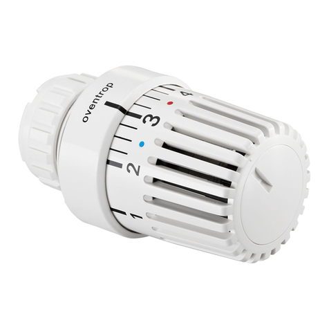
oventrop Cocon QTZ Operating instructions
oventrop
oventrop Uni LH User manual

oventrop
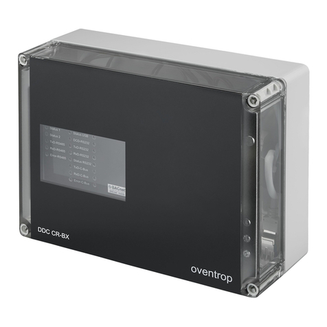
oventrop Regumat-180 Operating instructions
oventrop
oventrop DynaTemp DDC CR-BX User manual

oventrop
oventrop Cocon QTZ Manual
oventrop
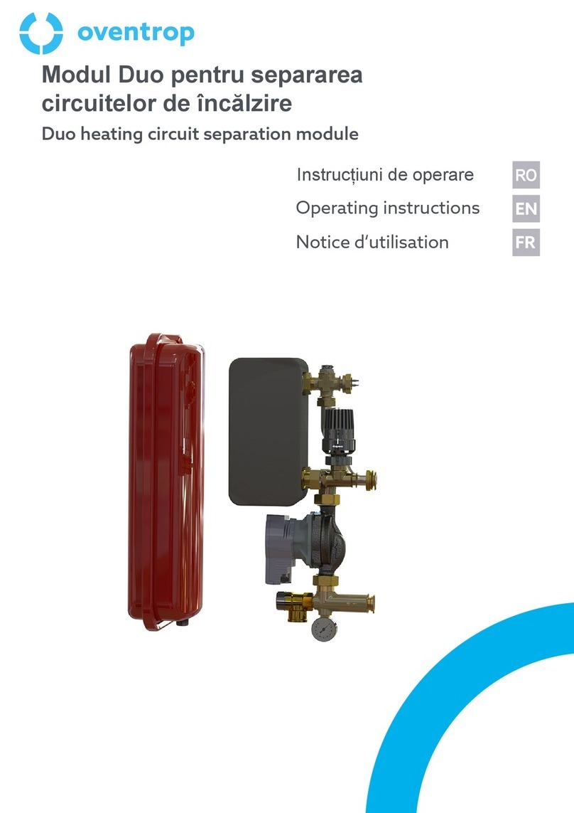
oventrop MODUL DUO User manual

oventrop
oventrop Aquastrom K User manual
Popular Control Unit manuals by other brands

Festo
Festo Compact Performance CP-FB6-E Brief description

Elo TouchSystems
Elo TouchSystems DMS-SA19P-EXTME Quick installation guide

JS Automation
JS Automation MPC3034A user manual

JAUDT
JAUDT SW GII 6406 Series Translation of the original operating instructions

Spektrum
Spektrum Air Module System manual

BOC Edwards
BOC Edwards Q Series instruction manual

KHADAS
KHADAS BT Magic quick start

Etherma
Etherma eNEXHO-IL Assembly and operating instructions

PMFoundations
PMFoundations Attenuverter Assembly guide

GEA
GEA VARIVENT Operating instruction

Walther Systemtechnik
Walther Systemtechnik VMS-05 Assembly instructions

Altronix
Altronix LINQ8PD Installation and programming manual
