Pace MBT 301 Instruction Manual

Operation and Maintenance Manual for the
PACE MBT 301® Digital
Soldering/DesolderingSystem
P/N 5050-0560 Rev. C: 3-15
This manual applies to: Version 2.3

©2013 PACE Worldwide, Southern Pines, North Carolina All Rights Reserved Page 2 of 18
INDEX
TITLE
PAGE
GeneralInformation
Introduction.......................................................................................
3
Specifications....................................................................................
3
EOS / ESD...................................................................................4
Capabilities .......................................................................................
4
MBT 301 Compatible Handpieces...............................................4
HandpieceTips............................................................................4
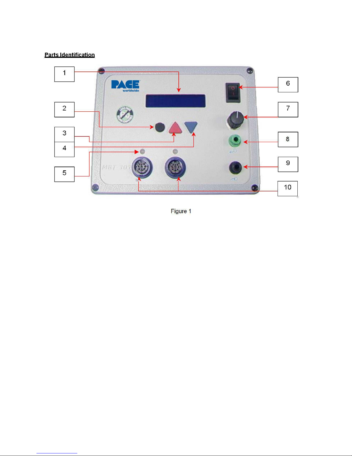
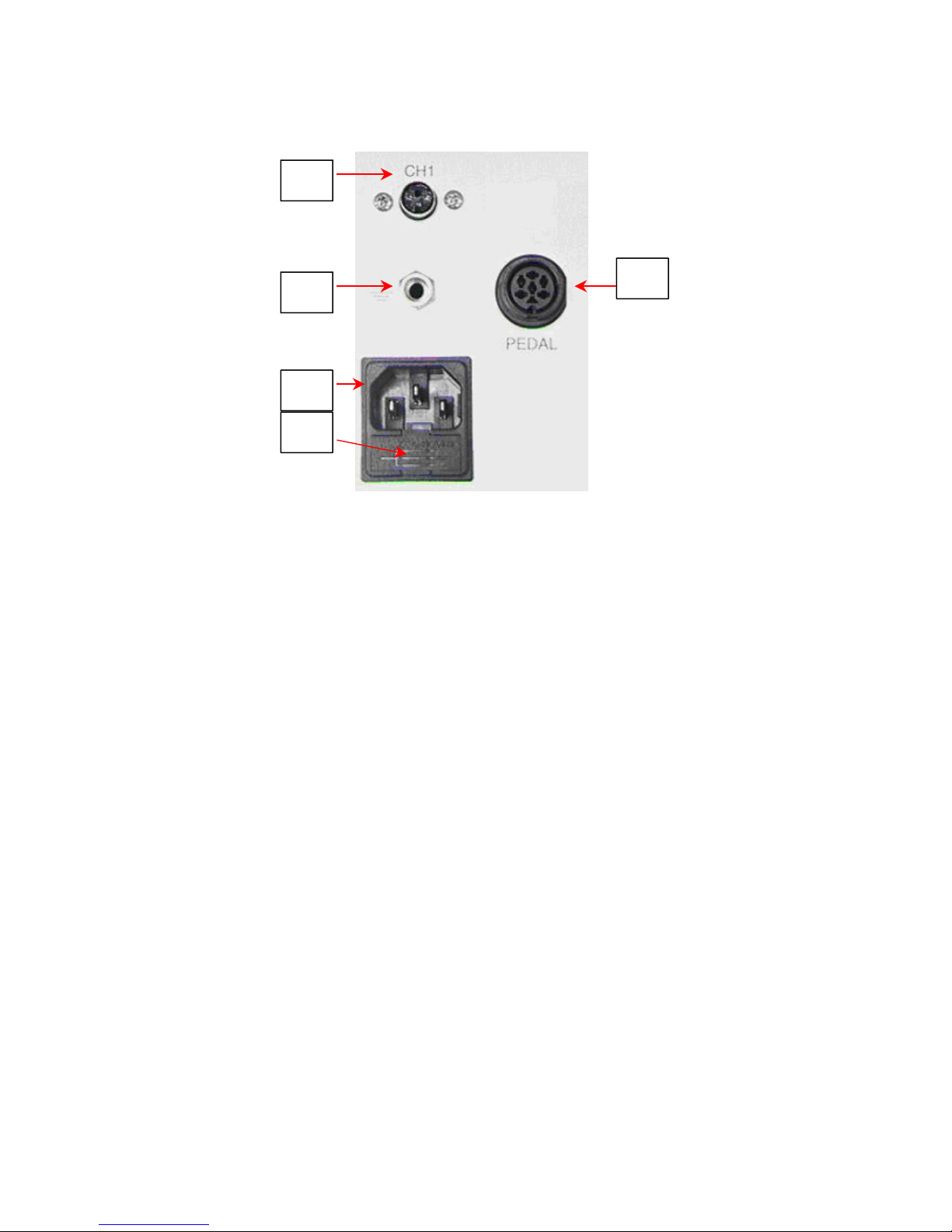
PartsIdentification .................................................................................5
SafetyGuidelines...................................................................................7
Safety........................................................................................................
8
UsageWarnings/Cautions...........................................................8
ServicingPrecautions..................................................................9
System Set-Up.......................................................................................9
Attaching Tip & Tool Stand.........................................................11
Instant Set Back Cubby..............................................................11
Tip Removal................................................................................11
Definitions...................................................................................................
12
System Power Up................................................................................12
LEDOperation......................................................................................13
Operation....................................................................................................
13
AccessingProgrammingMenu...................................................13
PasswordMenu..........................................................................13
Setting Temperature C /F ..............................................................13
Set Upper Limit...........................................................................14
Set Lower Limit...........................................................................14
Setback Time..............................................................................14
Set Auto Off ................................................................................14
Scan Enable / Disable.................................................................14
THC Calibration Offset Mode Select..........................................14
Set LCD Contrast........................................................................15
Set LED Backlite.........................................................................15
Exiting the Programming Menu ..................................................15
TemperatureAdjust Mode....................................................................15
Setting Channel Offset..........................................................................15
THC Tip Calibration ..............................................................................16
HelloMessage......................................................................................16
CorrectiveMaintenance........................................................................17
Packing List...........................................................................................17
Spare Parts...........................................................................................17
Service........................................................................................................
17
LIMITEDWARRANTYSTATEMENT...................................................18
ContactInformation...............................................................................18

©2013 PACE Worldwide, Southern Pines, North Carolina All Rights Reserved Page 3 of 18
GeneralInformation
Introduction
Thank you for purchasing the PACE model MBT 301 Soldering/Desoldering System. This manual will
provide you with the information necessary to properly set up, operate and maintain the MBT 301.
Please read this manual thoroughly before using the unit. The MBT 301 system is designed for the
most demanding soldering applications. The MBT 301 allows either SENSATEMP or TEMPWISE
technology handpieces to be plugged into any of 3, continuously active, handpiece channels. The
MBT 301 offers the benefits of SENSATEMP and TEMPWISE in a single system.
PACE’s legendarySENSATEMP technology is renowned for its temperature stabilityand ability to
handle high mass applications. For smaller components and when throughput is important, there is
TEMPWISE. TEMPWISE is a patented technology that boasts the best response time for high
volume applications and easily keeps up in a fast paced environment.
The MBT 301 unit is available in either the 115 VAC or 230 VAC versions. The 230 VAC version
system bears the CE Conformity Marking which assures the user that it conforms to all the
requirements of (EU) directive EMC 89/336/EEC & 73/23/EEC.
Specifications
POWERREQUIREMENTS
MBT 301 - Version operates on 97-127 VAC, 50/60 Hz.
240 Watts, 2 Amp max, 100% Duty Cycle, Motor on.
MBT 301E - Version operates on 196-253 VAC, 50 Hz.
240 Watts, 2 Amp max, 100% Duty Cycle, Motor on.
PHYSICALPARAMETERS
Size: 13.5 cm H x 16.5 cm W x 26 cm D (5.3"H x 6.5"W x 10.25"D)
Weight: 5 Kg. (11 Lbs.)
VACUUM AND AIR Measurements at front panel AUTO SNAP-VAC and CONTROLLABLE
PRESSUREPort.
Vacuum Rise Time: Evacuates 200 ms Average as measured with PACE Process Monitor
Vacuum: 20 in. Hg. (Nominal)
Pressure: (18 P.S.I.) (Nominal MAXIMUM setting)
Air Flow: 9 SLPM (0.32 SCFM) MAXIMUM
TEMPERATURESPECIFICATIONS
Tip Temperature Range: 37-482 °C (100-900 °F) SensaTemp
205-454 °C (400-850 °F) TempWise
Nominal (see note).
Digital Readout Resolution: ±1° (°C or °F)
Tip Temperature Stability: ±1.1°C(2°F) at Idle from Set Tip Temperature.
Temperature Accuracy: Meets or exceeds ANSIJSTD 001
NOTE
Actual minimum and maximum Operating Tip Temperatures may vary
depending on handpiece & tip selection.

©2013 PACE Worldwide, Southern Pines, North Carolina All Rights Reserved Page 4 of 18
EOS/ESD
Tip-To-Ground Resistance: Less than 5 ohms.
AC Leakage: Less than 2 millivolts RMS from 50Hz to 10MHz
ENVIRONMENTALREQUIREMENTS
Ambient Operating Temperature: 0°C to 50°C (32°F to 120°F)
Storage Temperature: -40°C to 100°C (-40°F to 212°F)
Capabilities
All capabilities are dependent upon the use of the appropriate Functional Accessories or Work Aids (refer
to Basic Operation section). Available SensaTemp and TempWise handpieces and their associated
assembly and repair functions are listed below. An Operations and Maintenance Manual is provided
separately with each handpiece which describes the applications and recommended procedures for that
particular tool.
The MBT 301 allows either SENSATEMP or TEMPWISE technology handpieces to be plugged into any
of 3, continuously active, handpiece channels. The new dual-purpose vacuum/pressure pump and
deliverysystem with PACE’s patented SNAP-VAC Technology, provides the most vacuum available for
desoldering applications. When used with an air pencil, the high resolution, pressure control valve allows
for precise adjustment when working onthe smallest components.
MBT 301 Compatible Handpieces (Blue Connector)
TD-100 handpiece - The most responsive soldering iron available. Uses tip-heater cartridges. TD-100 Kit
P/N 6993-0263-P1 Handpiece only P/N 6010-0147-P1
TD-100N handpiece – A nitrogen compatible version of the TD-100. Requires 6993-0271. TD-100N Kit
P/N 6993-0272-P1 Handpiece only P/N 6010-0156-P1
MT-100 handpiece – Tip heater cartridge tweezers for SMD removal.MT-100 Kit P/N 6993-0264-P1
Handpiece only P/N 6010-0148-P1
PS-90 Soldering Iron- Provides a wide range of SMD and thru-hole installation and removal capability as
well as unsurpassed thermal performance on heavy, multilayer thru-hole assemblies at safe, lower
working temperatures. A wide variety of 3/16" shank, quick change thru-hole and SMD tips (for chip
components, SOTs, SOICs and other components) are available. PS-90 Kit P/N 6993-0267-P1 Handpiece
only P/N 6010-0150-P1
PS-90N Soldering Iron- A nitrogen compatible version of the PS-90. Requires Nitrogen regulator kit P/N
6993-0271. PS-90N Kit P/N 6993-0274-P1 Handpiece only P/N 6010-0157-P1
SX-100 Sodr-X-Tractor handpiece - Air handpiece ideal for thru-hole desoldering on extra high
mass multilayer boards. SX-100 Kit P/N 6993-0266-P1 Handpiece only P/N 6010-0149-P1
TT-65 ThermoTweez handpiece - Performs removal of PLCC (J Leaded), LCCC (leadless) and other
surface mount devices. TT-65 Kit P/N 6993-0268-P1 Handpiece only P/N 6010-0151-P1
TJ-80 Mini Thermo Jet handpiece – Foot pedal activated precision air pencil for the installation or
removal of SMDs. TJ-80 Kit P/N 6993-0270-P1 Handpiece only P/N 6010-0153-P1
MBT 301 Handpieces tips
A complete list of available handpiece tips is available from your local PACE distributor or online at
www.paceworldwide.com.

©2013 PACE Worldwide, Southern Pines, North Carolina All Rights Reserved Page 5 of 18
Listed below is a description of the Control Panel features. Use Figures 1 & 2 as a guide.
1.
LCD DISPLAY - Provides temperature information for allthree channels. This includes: Operating Tip
Temperature in Temperature Display Mode (normal operation), Tip Offset Constant in Tip Offset Mode,
Set Tip Temperature in Tip Set Mode and other information in Calibration (CAL) Mode.
2.
PROGRAM KEY – Access tip offset feature and scroll through system channels.
3.
SCROLL UP KEY - Increases the Set Tip Temperature (in Tip Set Mode) and the Tip Offset Constant
(in Tip Offset Mode) in one, then ten-degree increments. Also used in (Calibration) Mode.
4.
SCROLL DOWN KEY - Decreases the Set Tip Temperature(in Tip Set Mode) and the Tip Offset
Constant (in Tip Offset Mode) in one then ten-degree increment. Also used in “CAL” (Calibration) Mode
5.
LED; CH 1 or CH 2 Illuminated LED’s change color to reflect handpiece connectivity. GREEN (circuit
complete) AMBER (in process) RED (no connection / error)
6.
POWER SWITCH - Turns system ON ("1") and OFF ("0"); controls input power to the system.
7.
PRESSURE ADJUSTMENT - Controls variable airflow pressure delivery (completelyopen for optimal
pressure).
8.
PRESSURE PORT – Quick connect fitting with provides airflow for Mini ThermoJet handpiece (in Hot
Jet Mode) and Sodr-X-Tractor handpiece. Air pressure is present when handpiece finger switch or
optional foot pedal is actuated. Air pressure ceases 1.2 seconds after switch (or foot pedal) is released
9.
AUTO SNAP-VAC PORT - Quick connect fitting provides quick-rise vacuum for Sodr-X-Tractor,
and ThermoPik handpieces. Vacuum is present when handpiece finger switch or optional foot pedal is
actuated. Vacuum ceases 1.2 seconds after switch (or foot pedal) released.
10.
CH 1 POWER RECEPTACLE - Provides power, tip ground, sensing circuitry and finger switch
connection from MBT system to handpiece connected to Channel 1 (CH 1).
CH 2 POWER RECEPTACLE - Provides power, tip ground, sensing circuitryand finger switch
connection from MBT system to handpiece connected to Channel 2 (CH 2).

©2013 PACE Worldwide, Southern Pines, North Carolina All Rights Reserved Page 6 of 18
Figure 2
11.
INSTANT-SETBACK CUBBY INPUT CHANNEL 1. Links handpiece on channel 1 to Instant-Setback
Cubby. For use with TD-100 handpiece only.
12.
EARTH GROUND RECEPTACLE - Provides positive earth groundto whicha ground cable can be
connected from the work piece or work surface as part of a static control program.
13.
AC POWER RECEPTACLE / FUSE HOLDER - Receptacle for providing power to the system from
AC outlet through power cord. Location of Fuse (F1), which protects system from over current conditions.
14.
FUSE - Provides overload protection for system.
15.
FOOT PEDAL RECEPTACLE - Inputfor Foot Pedal (optional), which activates vacuum or pressure
to the air-operated handpieces.
11
12 15
13
14

©2013 PACE Worldwide, Southern Pines, North Carolina All Rights Reserved Page 7 of 18
If you require assistance in the use of this product, contact your local authorized PACE dealer or
PACE directlyas shown on page 15 of this manual
SafetyGuidelines
The following are safetyprecautions that personnel must understand and follow when using or servicingthis
product.
1.
POTENTIAL SHOCK HAZARD- Repairprocedureson PACEproductsshould be performed by Qualified
Service Personnel only. Line voltage parts may be exposed when the equipment is disassembled.
Servicepersonnel must avoid contact with these parts when troubleshooting the product.
2.
To prevent personnel injury, adhere to safety guidelines in accordance with OSHA and other
applicable safety standards.
3.
Handpiece heaters and installed tips are hot when the handpiece is powered on and for a period of
time after power off. DO NOT touch either the heater or the tip. Severe burns may result.
4.
PACE Tip & Tool Stands and handpiece cubbies are designed specifically for use with the
associated handpiece and houses it in a manner that protects the user from accidental burns.
Always store the handpiece in its holder. Be sure to place the handpiece in its holder after use and
allow to cool before storing.
5.
Always use PACE systems in a well ventilated area. A fume extraction system such as those
available from PACE are highly, recommended to help protect personnel from solder flux
fumes.
6.
Exercise proper precautions when using chemicals (e.g., solder paste).Refer to the Material
Safety Data Sheet (MSDS) supplied with each chemical and adhere to all safety precautions
recommendedby the manufacturer.

©2013 PACE Worldwide, Southern Pines, North Carolina All Rights Reserved Page 8 of 18
Safety
PACE adheres to the following Heading Guidelines (based on OSHA guidelines) when listing special
information or precautions to be taken. Especially important are all procedures and practices which, if not
strictly observed, could result in injury or loss of life. These "NOTES", "CAUTIONS","WARNINGS" and
"DANGERS" are inserted in this manual whenever deemed necessary. They appear in a blocked off form
with double outline and a shaded background to highlight the information as shown below.
“NOTE”
Used to indicate a statement of company recommendation or policy. The message may relate
directly or indirectly to the safety of personnel or protection of property. NOTE is not associated
directly with a hazard or hazardous situation and is not used in place of "CAUTION", "WARNING"
or"DANGER".
“CAUTION”
Used to indicate a hazardous situation, which may result in minor or moderate injury. May also be
used to alert personnel to conditions, procedures and practices which, if not observed, could
result in damage to or destruction of the product or other equipment.
“WARNING”
Used to define additional information that if not closely followed might result in serious damage to
equipment and represent a potential for serious personnel injury.
“DANGER”
Defines additional information that if not closely followed might result in severe personnel injury or
death. Danger is not used for property damage unless personal injury risk is present.
UsageWarnings/Cautions
WARNINGS
1.
A fire hazard may arise if the MBT 301 is used improperly.
2.
Do not use the MBT 301 in the presence of an explosive atmosphere.
3.
Be careful when using the MBT 301 in places where there are combustible materials.
Heat may be conducted to combustible materials, which are out of sight.
4.
Do not apply heat from the MBT 301 to one place for a long time.
5.
Do not leave the MBT 301 unattended while powered on.
NOTE

©2013 PACE Worldwide, Southern Pines, North Carolina All Rights Reserved Page 9 of 18
CAUTIONS
1.
Utilize all standard electrical safety precautions when using this or any other electrical
equipment.
2.
Always use this system in a well-ventilated area. A fume extraction system such as those
available from PACE are highly recommended to protect personnel from solder flux
fumes.
5. Exercise proper precautions when using chemicals (e.g., solder paste). Refer to the
Material Safety Data Sheet (MSDS) supplied with each chemical and adhere to all safety
precautions recommended by the manufacturer.
ServicingPrecautions
DANGERS
POTENTIAL SHOCK HAZARD - Repair procedures performed on this product should be
performed by qualified service personnel only. Line voltage parts will be exposed when
equipment is disassembled. Service personnel must avoid contact with these parts when
troubleshooting.
Precautions
The following are general safety precautions that personnel must understand and follow when
using or servicing this product. These precautions may or may not be included elsewhere in this
manual.
Safety
ElectricalRequirements
The MBT 301 unit draws approximately 240 VA (240Watts), which is listed on the nameplate
on the power source rear panel. A separate, dedicated AC supply line circuit may be required
to adequately power the unit/system. If your power outlet cannot provide suitable power,
arrange for a qualified, licensed electrician to install one for you.
System Set-Up
Power Source
Set up the MBT 301 system using the following steps and associated drawings.
1.
Remove the MBT 301 from its shipping container(s). Store the shipping container(s) in a
convenient location. Reuse of these containers will prevent damage if you ship or store
the system.
2.
Set the MBT 301 unit on a convenient workbench.
3.
Place the POWER Switch (on power source front panel) in the "OFF"
or "0" position.

©2013 PACE Worldwide, Southern Pines, North Carolina All Rights Reserved Page 10 of 18
4.
Inspect all system components, check for shipping damage, and ensure that all
purchased components (standard and options) are present. Use the drawings provided
in the following pages as a guide for checking the parts that come with the unit.
5.
Assemble Tip & Tool Stands. Attach to the power source if desired. Assembly
instructions are enclosed with each Tip & Tool Stand.
6.
Connect blue handpiece connector plug(s) to
the blue power receptacle(s) CH 1, and/or CH
2 in the following manner. See Fig. 3a.
a)
With the Connector Keyend facing the
power source, turn the Locking Ring fully
counterclockwise.
b)
Orient guide on connector with slot of
powerreceptacle.
c)
Insert connector into power receptacle.
d)
Turn Locking Ring fully clockwise to lock
in place.
7.
To avoid confusion among handpieces, PACE
recommends the use of colored cable markers
(P/N 6993-0136 Cable Marker Kit) to identify
the particular handpiece. Attach any two like
colored markers, one to each end of the
handpiece power cable or air hose. Select and
use a different colored marker for each
handpiece. Labels are also provided to mark
Tip & Tool Stands with the name of the
associatedhandpiece.
8.
If you have purchased an optional foot pedal,
insert the connector plug into the PEDAL
Receptacle on the rear panel of the power
source. See Fig. 3b. Install additional
handpieces and accessories as necessary.
9.
Plug the prong end of the power cord into a
convenient three wire grounded AC power
outlet. The system is now ready for operation.
Figure 3b
10.
Read the "OPERATION" section of this manual thoroughlybefore operating the system.
Figure 3a

©2013 PACE Worldwide, Southern Pines, North Carolina All Rights Reserved Page 11 of 18
Attaching Tip & Tool Stand to MBT 301
Attach the stand to the power source, using the following procedure. Refer to illustration.
1.
Insert the 2 enclosed hex head Mounting Screws into the slot on the side of the Power Source. Some
kits may contain 4 mounting screws; 2 with small heads and 2 with large heads. Use the 2 screws that fit
properly in the slot. Also, some Power Source cases have more than 1 slot; use the lower slot.
2.
Position the Mounting Screws to the rear of the power source and
spaced approximately2 inches apart. Refer to illustration.
3.
Place the Tip & Tool Stand beside the power source. Insert ends
of the 2 Mounting Screws into the 2 adjacent Tip & Tool
Stand mounting holes.
4.
Install a Thumb Nut onto the end of each Mounting Screw. Tighten
Thumb Nuts to secure the Tip & Tool Stand in position.
You may wish to set the Power Source on its side and remove the
drip tray to ease installation of the Thumb Nut.
5.
Additional Tip & Tool Stands or “cubby’s” may be secured to each
other by aligning mounting holes on stand sides. Use hex head
screws and thumb nuts to mount cubbys together.
Optional Instant-Setback Cubby Figure 4
The optional Instant SetBack Cubby is available for use with the MBT 301 and will onlyfunction with the
TD-100 handpiece. When connected, it automatically puts the system into Setback mode when the TD-
100 is placed in the cubby. The Instant Setback Cubbywill only function with the TD-100 Handpiece.The
instant SetBack receptacles are located on the back panel. See figure 3. The instant setback cubby's
function is to protect tips, not power off the system. Instant setback is a feature that lowers the
temperature to 350°F after 45 seconds of inactivity. At 350°F the solder has solidified so any iron erosion
on the tips ceases, protecting the tip.
Tip Removal
WARNING
Never remove a heated tip using bare hands. Use the Hot Grip Rubber Pad or Tip Tool.
Never use a wrench or pliers when removing a handpiece tips.

©2013 PACE Worldwide, Southern Pines, North Carolina All Rights Reserved Page 12 of 18
WARNING:
1.
Remove TD-100 and MT-100 handpieces while holding Tip Heater Cartridge with the Rubber
Pad; gently pull the THC from handpiece. For PS-90, SX-100, TT-65, and TJ-80 handpieces,
loosen heater set screw and remove iron tip with Rubber Pad.
2.
Place the tip (still hot) in tip / tool stand.
Definitions
Please read and become familiar with the definitions of each of the following terms that are used
repeatedlyin the following operational procedures.
Auto-Off: Safetyfeature that turns power off (1-90 minutes, settable in 1 minute increments) after the
system has entered Temperature Setback.
Normal Operation: Normal operating mode of the system in which the Operating Tip
Temperature is displayed.
Password: The Password feature of theMBT 301 system will prevent unauthorized alteration of
stored system temperature parameters and featuresettings. If a Password has been installed,
the LCD Display will display an instruction to enter the password. Enter a four digit number selected
using the scroll up /down keys on the system front panel) when a setting change is attempted.
Programming Menu: The interface used to program the system features parameters (e.g.,
temperature limits, password, setback time).
Set Tip Temperature: The operator selected idle tip temperature entered into thesystem memory.
Temperature Adjust Mode: Mode of operation where the Set Tip Temperature may be adjusted.
Temperature Setback: System feature that will independently set back the Set Tip Temperature to
177°C (350°F) after a user selected or preset period of handpiece inactivity.
System Power Up
1.
Insert the female end of the power cord into the AC Power Receptacle on the rear panel of
the power source.
2.
Plug the prong end (male end) of the power cord into an appropriate 3 wire grounded AC
supplyreceptacle.
CAUTION
To insure operator and ESD/EOS safety, the AC power supplyreceptacle must be checked for
proper grounding before initial operation.

©2013 PACE Worldwide, Southern Pines, North Carolina All Rights Reserved Page 13 of 18
LED Operation
The Green colored Temperature LED on the power source front panel indicates System Status.
LED Green - Indicates that the set tip temperature has been reached. Power to the handpiece is
cycling Off and On to maintain set temperature.
LED Amber - Continuous power is being delivered to the handpiece. This condition is evident
when the system is first powered up (handpiece heater cold) or the Variable Temperature Control
setting is increased.
LED Red - No power is being delivered to the handpiece heater. If the LED never illuminates,
check for a faulty handpiece heater (see Corrective Maintenance section).
Operation
Accessing Programming Menu
The menu driven LED Display of the MBT 301 system allows you to easily customize your system. By
accessing the programmingmenu, you can:
•
Enter, remove or change a Password.
•
Set the Default Temperature scale to °F or °C as desired.
•
Change the Upper and Lower Temperature limits.
•
Enable or disable the Temperature Setback feature.
•
Enable or disable the Auto Off feature.
•
Enable or disable the Scan feature.
•
Change the Default Calibration Offset Option
•
Calibration Option 2 LED reset capability
•
Enable or disable the display contrast and backlight settings.
To access set up mode, press and hold the PROGRAM Key while powering on unit. Release key
when “Software Version” appears. Pressing the PROGRAM Key will scroll through each menu
option without changing the stored setting.
Follow the MBT 301’s on screen prompts to review or set each menu option starting with the
passwordfeature.
1.
PasswordMenu
Same Retains previous password and move to the next step.
Yes
Prompts the operator to enter a new password. Use the scroll up / down keys on the
system front panel to select a four digit password. Once password is entered, press the
PROGRAM Key to accept the password and move to the next step. Entering “0000” as
a password will disable the password feature.
No
Selecting “NO” bypasses the password feature and moves to the next step.
2.
Setting Temperature C /F
The LED Display now shows the stored default Temperature Scale °C or °F temperature shown on
LED Display). Choose one of the following:
a)
Press the PROGRAM Key to keep the stored default Temperature Scale.
b)
Press and release the UP Key to change the default Temperature Scale.
Press and release the PROGRAM Key to move to the next step.

©2013 PACE Worldwide, Southern Pines, North Carolina All Rights Page 18 of 18
3.
Set Upper Limit
Hit the PROGRAM key to cycle through different channels, to set channel specific upper limits.
Press the UP and DOWN button to set the upper temperature limit for the handpiece channels.
900°F (482˚C) is the MAXIMUM temperature limit for SensaTemp handpieces. The MAXIMUM
temperature for THC handpieces is 850°F (454°C). Press and release the PROGRAM Key to move
to the next step. The upper limit feature will limit the temperature range that an operator may work
within. Setting a password will lock out unwanted changes to this feature.
4.
Set Low Limit
Hit the PROGRAM key to cycle through the different channels, to set the channel specifc upper
Limits. Press the UP and DOWN button to set the lower temperature limit for the handpiece
Channels.100°F (37°C) is the MINIMUM temperature for SensaTemp handpieces. The MINIMUM limit
for THC handpieces is 400°F(204°C). Press and release the PROGRAM Key to move to the next
stepThe lower limit feature will limit the temperature range that an operator may work within. Setting a
password will lock out unwanted changes to this feature. Adjusting the working temperature below the
set lower limit will turn power off to the selected channel.
5.
SetBackTime
Choose one of the following:
a)
Press and release the PROGRAM Key to keep the currently stored Temperature Setback
time.
b)
Press and release the Scroll UP Key to enable or increase the stored Temperature Setback
time. Press and release the PROGRAM Key to proceed to the next step. Set back may be
disabled by entering (00). The maximum set back time is 90 minutes.
c)
Press and release the Scroll Down Key to decrease or enter “00” to disable the stored
Temperature Setback time. Press and release the PROGRAM Key to proceed to the next
step.
The LED Display now shows the stored Temperature Setback time in minutes
6.
Set Auto Off
Press the UP Key to enter increase the auto-off time. When enabled, the Auto Off safety system of
the MBT 301 system turns off the power to the Handpiece 1- 90 minutes after entering Temperature
Setback.When the system has enteredTemperature Setback, an Auto Off timer within the system
circuitry will start running if Auto Off is turned on. When Auto Off has activated, the LED Display will
blink “OFF”. To disable the Auto-Off feature, enter “00”. If any key is pressed during the selected time
out period, the Auto Off timer is reset. The system will return to normal operation. At the end of the
time out period, the system will enter Auto Off. Power is turned off to the heater and the LED Display
will show a flashing “OFF ” and the LED indicator will turn red. Press and release the PROGRAM Key
to move to the next step.
7.
THC Calibration Offset Mode Select
When a channel has NOT been calibrated the “C” in channel (“CH”) will display a BLINKING dot in the
center of the “C”. See image below:
Channel 1 has not been calibrated, Channel 2 has been calibrated. The “calibration” indicator will
appear in Scan and normal display modes. Additionally, NO dot will appear when a SensaTemp
handpiece has been connected to the system as it does not require calibration.
a)
Screen will display “Set Offset Mode”
b)
Change the Offset Option by pressing the UP and DOWN
c)
Choose one of the following options:
i.
“OS Mode 1” (Offset Mode 1) Offset will clear to zero if either the handpiece or the tip

©2013 PACE Worldwide, Southern Pines, North Carolina All Rights Page 18 of 18
is removed from the system. A BLINKING dot will appear in the center of the “C”.
This option could be selected when a variety of different tips are being used
and the system should recalibrated after every tip change
This option is suitable if replacing the tip or the handpiece would always
require the system to be recalibrated
ii.
“OS Mode 2” (Offset Mode 2) Offset will clear to zero if the handpiece is removed from
the system, but removing the tip will maintain the offset. A STEADY dot will appear in
the center of the “C” if the tip is removed.
This option is desirable when using tips of similar geometry where it is not
necessary to formally recalibrate after a tip change.
This option would be desirable in situations where supervisors would want to
be able to easily determine if the tip has been removed for any reason
iii.
“OS Mode 3” (Offset Mode 3) Offset will clear to zero if the handpiece is removed from
the system, but removing the tip will keep the offset. There will be no dot if the system
has an offset. In this mode, the BLINKING dot will only appear if the handpiece is
removed (this is the Factory Default Mode).
This option could be selected in applications when a the tip is rarely replaced
or when the same style tip is used throughout the application
This option is suitable if only replacing the handpiece would require the system
to be recalibrated
d)
Press and release the PROGRAM Key to proceed to the next step.
8.
OS Mode reset option- Turn on or off the reset options
i) “OS Mode 2 Reset ?= ON:- The line operator/user has the ability to reset the offset
indicator by going through the reset sequence. (See resetting the THC Cal indicator
below) 1) If a THC handpiece is hooked to the channel being displayed, then
pressing the UP key will rest the calibration indicator/dot
2) If a SensaTemp handpiece is hooked to the channel being displayed
then you can cycle to the corresponding channel by holding the program
key for 5 seconds, and set the offset.
ii) “OS Mode 2 Reset ?= OFF:
a) Under this mode, the access to the reset capability of the Calibration
indicator/DOT is not available.
9. Set LCD Contrast
Press the UP and DOWN to enter increase or decrease LCD contrast. The range of
contrast is
1 to 100. Press and release the PROGRAM Key to move to the next step.

©2013 PACE Worldwide, Southern Pines, North Carolina All Rights Page 18 of 18
10. Set LED Backlite
Press the UP and DOWN to enter increase or decrease LCD contrast. The range of backlite is
1 to 100. Press and release the PROGRAM Key to move to the next step.
11. Exiting the Programming Menu
The LED Display now reads "End". The Set-Up Mode procedure is now complete. Choose one
of the
followingsteps:
a)
Press and release the UP Key to exit Set-Up Mode and return to normal operation.
b)
Press and release the DOWN Keyto return to the start of the Set-Up Mode procedure.
Temperature Adjust Mode
To increase or decrease handpiece temperature, press the UP or DOWN arrow key once. The
display will show the current temperaturesetting for channel “1”. Press the UP
or
DOWN
arrow keys to increase or decrease handpiece temperature for channel “1”. Or press the
PROGRAM Key to move the next channel. After a period of 10 seconds of inactivity, the display will
return to normal operation.
Setting Channel Offset or resetting THC Cal Indicatior (OS mode 2)
To increase or decrease handpiece temperature offset, press the PROGRAM Key once. The display
will show the current temperature offset setting for channel “1”. Press the UP
or DOWN
arrow
keys to increase or decrease offset temperature for channel “1”. Or press the PROGRAM Key to
move the next channel. After a period of 10 seconds of inactivity, the display will return to normal
operation.
THC Tip Calibration
To enter Calibration mode: Press and hold the PROGRAM Key and the UP keys while
powering on unit. Release keys when “Software Version” appears. Follow the instructional prompts
to review or set each menu option. Follow the procedure below.
CalibrationInstructions
The steps for the procedure are:
1.
Turn on the system.
2.
Clear any offset from the system by disconnecting the handpiece from the system. Re- connect the
handpiece and proceed to step 2.
3.
A BLINKING dot will appear in the center of the "C" in channel (“CH”). Set the MBT 301 to 700°F to
(370°C).
4.
Measure the actual temperature of the tip from your temperature verification device.
Note
results.
5.
Turn off the system.
6.
Enter Calibration mode: Press and hold the PROGRAM Key and the UP key while
turning the system on. Release both keys when the display reads version 1.2 or higher.
7.
The display will now read Channel “1” System Cal? Press the UP or DOWN key to enter
the measured temperature from step 4 for channel “1”. For example, your temperature
verification device reads 695 °F. Scroll through until the display reads 695. Press key / NO to
move to the next channel.
8.
Press the PROGRAM Key to save calibration and move to the next channel. Upon exiting,
LED will illuminate green and the display will return to normal operation mode.
9.
See calibration options in the THC Calibration Offset Mode Select section of the manual.

©2013 PACE Worldwide, Southern Pines, North Carolina All Rights Page 18 of 18
CorrectiveMaintenance
Power Source
Refer to the table below. Most malfunctions are simple and easy to correct.
Symptom Probable Cause Solution
No powe
r
to system Blown Fuse Inspect and replace the fuse(s) located on the power source
rea
r
p
anel
Line cord unplugged Plug line cord into the appropriate AC outlet
Heater Assembly does not
heat Open Heate
r
Contact PACE fo
r
assistance
Little or no air flow, heater
heats and blower is running Kinked ai
r
hose Change routing of air hose to remove
kinks
Little o
r
no vacuum Worn vacuum pump Replace vacuum pump. Contact PACE fo
r
assistance.
Vacuum Cup will not hold
component Worn or broken
vacuum cup Replace vacuum cup
Vacuum Pickup Rod binding Vacuum Pickup rod is
bent Contact PACE fo
r
assistance
Packing List
Item # Description Part Number MBT 301
Only MBT 301 E
Only MBT 301
System MBT 301 E
System
1 System Powe
r
Supply 8007-0480 1 0 1 0
2 System Powe
r
Suppl
y
(Export) 8007-0481 0 1 0 1
3 Powe
r
Cord, 115V 1332-0094-P1 1 0 1 0
4 Powe
r
Cord, 230V 1332-0093-P1 0 1 0 1
5 Hot Grip Removal Pad 1100-0307-P1 0 0 1 1
6 Fibe
r
Cleaning Tool 1100-0232 0 0 1 1
7 Cleaning Sponge Tool 1100-0233 0 0 1 1
8 Wire Brush 3/16 Diamete
r
1127-0014 0 0 1 1
9 Cable Marke
r
Kit 6993-0136-P1 0 0 1 1
10 Angle Bracket Kit 6018-0097-P1 0 0 1 1
11 PACEScrewdrive
r
1100-0230 0 0 1 1
12 SX-100 (Blue Connector) Kit 6993-0266-P1 0 0 1 1
13 MT-100 ((Blue Connector) Kit 6993-0264-P1 0 0 1 1
14 TD-100 (Blue Connector) Kit 6993-0263-P1 0 0 1 1
15 Operations Manual CD 5050-0459 0 0 1 1
Spare Parts
Item # Description PACE Part Numbe
r
1 Fuse, 2.0
A
, 125 V, Lag Time (MBT 301) 1159-0275-01-P5
2 Fuse, 1.25
A
, 230 V, Lag Time (MBT 301E) 1159-0275-02-P5
NOTE
Before calibration is attempted, the system should be allowed to reach set temperature and
stabilize for at least 15 seconds before calibrating.

©2013 PACE Worldwide, Southern Pines, North Carolina All Rights Page 18 of 18
Service
Please contact PACE or your local distributor for service and repair.
PACE Incorporated retains the right to make changes to specifications contained herein at any time,
without notice. Contact your local authorized PACE Distributor or PACE Incorporated to obtain the latest
specifications.
The following are trademarks and/or service marks of PACE, Incorporated, NC, USA:
INSTACAL™, FUMEFLO™, HEATWISE™, PACEWORLDWIDE™, PERMAGROUND™,
POWERPORT™, POWERMODULE™, TEMPWISE™, TIP-BRITE™, AUTO-OFF™, and
TEKLINK™.
The following are registered trademarks and/or service marks of PACE Incorporated, Southern Pines
North Carolina U.S.A.
ARM-EVAC®, FLO-D-SODR®, MINIWAVE®, PACE®, SENSATEMP®, SNAP-VAC®,
SODRTEK®, SODR-X-TRACTOR®, THERMOFLO®, THERMOJET®, THERMOTWEEZ®,
VISIFILTER®,THERMO-DRIVE®,andTOOLNET®.
PACE products meet or exceed all applicable military and civilian EOS/ESD, temperature stability and
other specifications including MIL STD 2000, ANSI/JSTD 001, IPC7711, and IPC A-610.
For PACE USA Customers:
PACE, INCORPORATED
255 Air Tool Drive
Southern Pines,
North Carolina, 28387
Tel: (877) 882-PACE
Tel: (910) 695-7223
Fax: (910) 695-1594
For PACE EUROPE Customers:
PACE EUROPE LIMITED
13 Tanners Drive, Blakelands
Milton Keynes
MK1 45BU
United Kingdom
Tel. (44) 1908 277666
WARRANTY SERVICE FAX: (44) 1908 277 777
www.paceworldwide.com
www.facebook.com/paceworldwide
Table of contents
Other Pace Soldering Gun manuals

Pace
Pace ST 25 User manual

Pace
Pace SODRTEK ST 125 User manual

Pace
Pace ADS200 User manual

Pace
Pace MBT250 Manual

Pace
Pace TJ-70 Instruction Manual

Pace
Pace ST 25 User manual

Pace
Pace ADS200 Instruction manual

Pace
Pace ST 40A Manual

Pace
Pace MBT360 User manual

Pace
Pace MicroBenchtop MBT-100 Troubleshooting guide