manuals.online logo
Brands
  1. Home
  2. •
  3. Brands
  4. •
  5. Panduit
  6. •
  7. Cables And Connectors
  8. •
  9. Panduit FSCMM Series User manual

Panduit FSCMM Series User manual

For Technical Support: www.panduit.com/resources/install_maintain.asp
INSTALLATION INSTRUCTIONS
© Panduit Corp. 2014 FS069
Page 1 of 12
TABLE OF CONTENTS Page(s)
Safety Precautions 2
900µm Tight-Buffered Fiber Termination 3-6
Jacketed Cable Termination 7-12
CONNECTOR ASSEMBLY
ITEM PART
NUMBER DESCRIPTION
1 FVFLY Visual Fault Locator
2 FVFLPCY VFL Patch Cord
3 CST-115 Fiber Cable Jacket Stripper
4 FALC Alcohol Bottle (empty)
5 FBFSP Fiber Buffer Stripper
6 FCRP5 Universal Crimp Tool (hex sizes: .048, .100, .128, .151, .190)
7 FJQCVR Fiber Cleaver
8 FGLS Safety Glasses
9 FKS Strength Member (Aramid Fiber) Cutters
10 FSTY Safety Stickers for fiber scraps
11 FSWB-C Cleaning Swabs
12 FWP-C Cloth Wipes
13 PFX-0 Indelible Ink Marking Pen
14 -- Isopropyl Alcohol (Reagent Grade, 90% minimum concentration; not available from Panduit)
15 FLPT Crimp Tool (For 2.0mm/1.6mm terminations only)
16 FHSCT 110VAC/60Hz Heat Shrink Curing Tool (For 2.0mm/1.6mm terminations only)
FHSCT-W 230VAC/50Hz Heat Shrink Curing Tool (For 2.0mm/1.6mm terminations only)
OPTIONAL FS091* SC Opti-Crimp Connector Stripping Template
OPTIONAL FJQCVRB Replacement Blade for Fiber Cleaver
ITEMS REQUIRED FOR TERMINATION
DUPLEX
SIMPLEX
FSCMM**
FSCDMM
FSCMM50**
FSCDMM50
Dust cap
Duplex clip
Outer housing
Inner housing
assembly
Backbone
3.0mm crimp 900µm buffered
sleeve boot
2.0mm/1.6mm
crimp sleeve
FSCMM2.0**
FSCMM502.0**
Jacketed boot
FSCMM**, FSCMM50**, FSCDMM and
FSCDMM50 include 3.0mm crimp sleeves.
FSCMM2.0** and FSCMM502.0** include
2.0mm/1.6mm crimp sleeves.
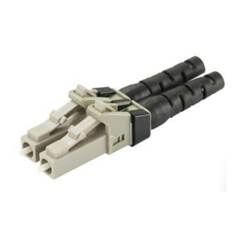
SC Opti-Crimp Multimode Fiber Optic Connector
Part Numbers: FSCMM**, FSCMM2.0**, FSCMM50**, FSCMM502.0**,
FSCDMM, FSCDMM50
COMPONENT IDENTIFICATION
READ ALL INSTRUCTIONS COMPLETELY BEFORE PROCEEDING
* Denotes revision letter.
** Denotes color.
For Technical Support: www.panduit.com/resources/install_maintain.asp
INSTALLATION INSTRUCTIONS
© Panduit Corp. 2014 FS069
Page 2 of 12
SAFETY PRECAUTIONS
1. SAFETY GLASSES
WARNING: IT IS STRONGLY RECOMMENDED THAT SAFETY GLASSES
BE WORN WHEN HANDLING BARE OPTICAL FIBER. THE BARE FIBER IS
VERY SHARP AND CAN EASILY DAMAGE THE EYE.
2. ISOPROPYL ALCOHOL
WARNING: ISOPROPYL ALCOHOL IS FLAMMABLE. CONTACT WITH THE
ALCOHOL CAN CAUSE IRRITATION TO THE EYES. IN CASE OF CON-
TACT WITH THE EYES, FLUSH WITH WATER FOR AT LEAST 15 MINUTES.
ALWAYS USE ISOPROPYL ALCOHOL WITH PROPER LEVELS OF VENTI-
LATION. IN CASE OF INGESTION, CONSULT A PHYSICIAN IMMEDIATELY.
3. DISPOSAL OF BARE FIBERS
WARNING: PICK UP AND DISCARD ALL PIECES OF BARE FIBER WITH
STICKY TABS. DO NOT LET CUT PIECES OF FIBER STICK TO CLOTHING
OR DROP IN THE WORK AREA WHERE THEY ARE HARD TO SEE AND
CAN CAUSE INJURY.
4. LASER LIGHT PROTECTION
WARNINGS:
• LASER LIGHT CAN BE INVISIBLE. THE INVISIBLE LIGHT IS POWERFUL
ENOUGH TO DAMAGE YOUR EYES. THE FVFLY VISUAL FAULT LOCA-
TOR CONTAINS A CLASS II LASER PRODUCT THAT HAS A VISIBLE
RED LASER. UNDER NORMAL CORRECT OPERATION, THE FVFLY
VISUAL FAULT LOCATOR IS SAFE TO THE HUMAN BODY.
• NEVER LOOK INTO THE PATH OF THE FVFLY VISUAL FAULT LOCATOR
OR ANY OTHER LASER BEAM.
• NEVER LOOK INTO THE END OF A FIBER WHICH MAY HAVE ANY
VISUAL FAULT LOCATOR, OR ANY OTHER LASER, COUPLED TO IT.
• DIRECT EYE CONTACT WITH LASER BEAM MAY CAUSE SERIOUS EYE
INJURY AND SHOULD BE AVOIDED AT ALL COSTS. IF DIRECT EYE
EXPOSURE HAS BEEN SUSPECTED, SEEK MEDICAL ATTENTION
IMMEDIATELY.
• NEVER LAUNCH ANY VISUAL FAULT LOCATOR INTO ACTIVE EQUIP-
MENT OR MICROSCOPE. MAKE SURE THAT THE END OPPOSITE THE
FVFLY VISUAL FAULT LOCATOR IS NOT CONNECTED TO ANY ELEC-
TRONICS OR ACTIVE EQUIPMENT DURING TERMINATION.
CAUTION: Use of controls or adjustments or performance of procedures other
than those specified herein may result in radiation exposure. Tampering with the
visual fault locator or any labels in any way may also result in injury and voids
warranty.
5. CABLE HANDLING
WARNING: FIBER OPTIC CABLE CAN BE DAMAGED BY EXCESSIVE
PULLING, TWISTING, CRUSHING OR BENDING STRESSES. CONSULT
THE APPROPRIATE SPECIFICATION SHEETS AS PROVIDED BY YOUR
CABLE VENDOR. ANY DAMAGE MAY DECREASE OPTICAL PERFOR-
MANCE.
CLASS II LASER
For Technical Support: www.panduit.com/resources/install_maintain.asp
INSTALLATION INSTRUCTIONS
© Panduit Corp. 2014 FS069
Page 3 of 12
1. LOADING INNER HOUSING ASSEMBLY INTO FCRP5 CRIMP TOOL
1.1 IMPORTANT: TOOL MUST HAVE A “P” ON THE
LOWER CRIMP DIE (SEE FIGURE 1.1), IF NOT,
PLEASE CONTACT TECHNICAL SUPPORT. Pull fer-
rule assembly retainer clip away from tool and rotate the
clip until the “SC” lettering on the crimp die is visible.
Release clip.
Note: Some clips have a small bump on one side. If
there is a bump on the clip, be sure to align the clip so
that when the “SC” lettering is visible, the bump is facing
away from the crimp dies and the “FJ” lettering is point-
ing towards the handle of the tool.
1.2 Remove the dust cap from the metal end
(rear) of the inner housing assembly. Place
the inner housing assembly onto the .100"
hex crimp pocket (die size numbers are on
crimp die on the opposite side) of the
FCRP5 crimp tool. Locate the inner housing
assembly so that the crimp die pocket
passes through the crimp thru window and
onto the ferrule assembly. When loaded, the
“SC” lettering on the crimp die should strad-
dle the ferrule holder.
1.3 Partially close the tool to contain the inner
housing assembly. DO NOT CRIMP THE
FERRULE HOLDER.
1.1
Bump
SC
lettering
1.3
Tool
Gap
Inner
Housing
Assembly
Ferrule holder
Crimp die
Crimp Thru
Window
Ferrule holder
Retainer clip
1.2
900µm Tight-Buffered Fiber Termination
For Technical Support: www.panduit.com/resources/install_maintain.asp
INSTALLATION INSTRUCTIONS
© Panduit Corp. 2014 FS069
Page 4 of 12
3. STRIPPING 900µm TIGHT-BUFFERED FIBER
3.1 Insert the fiber end through the small end of the boot. Slide the
boot back out of the way.
3.2 Following the stripping dimensions, use the marking pen to
place a mark 1.18" (30mm) from the end and place an insertion
mark 0.53" (13.5mm) back from the first mark.
3.3 Use the buffer stripper provided to strip the buf-
fer to the buffer removal mark.
BUFFER STRIPPING GUIDELINES:
• Panduit recommends that you remove no more
than 1/4" (6.4mm) of buffer at a time to avoid
breaking the fiber. Refer to cable manufacturer's
buffer stripping guidelines for specific recommen-
dations.
• Hold the buffer stripper such that the arrow on
the tool points in the direction of buffer removal.
• Noting the location of the tool's blades, position
the fiber in the tool's V-notches. Squeeze the handles firmly, and
pull tool in the direction of the arrow on the tool.
• Clean the buffer stripper blades after each strip by holding the
handles open, pulling the casings back away from the blades,
and letting them snap back against the blades.
2. CONNECTING FVFLY TO INNER HOUSING ASSEMBLY
2.1 Verify that Visual Fault Locator (FVFLY) is “OFF” (green LED is
off). Remove the metal dust cap from the FVFLY. Remove the
dust cap from ST Connector on the Visual Fault Locator Patch
Cord (FVFLPCY) and insert the ST Connector into the output
end of FVFLY until the ferrules touch. Remove the dust cap from
the Ferrule Adapter end of the FVFLPCY.
Note: NEVER rotate the FVFLPCY when mated to the FVFLY
or another connector. This will cause damage to the FVFLPCY,
the FVFLY and the connector.
2.2 Remove the dust cap from the connector ferrule in the FCRP5
Crimp Tool. Mate the Ferrule Adapter end of the FVFLPCY to the connector ferrule.
Note: The connector ferrule assembly and the ferrule contained in the Ferrule Adapter should touch.
2.3 Turn the FVFLY “on” by pressing & holding the ON/OFF button for 2-3 seconds. Note that when the FVFLY is
switched “on”, the connector ferrule glows red. Place the tool, FVFLY and FVFLPCY down gently on a clean
surface. Be careful not to damage the ferrule assembly.
ON/OFF
HOLD 2 Sec 2 Hz
O
N
/O
FF
HOLD 2 Se
c
2
H
z
ON/OFF
HOLD 2 Sec 2 Hz
2.1
ST Connector
Ferrule
Adapter End
FVFLPCY
FVFLY
900µm TIGHT-BUFFERED STRIPPING DIMENSIONS
IMPORTANT! Due to printing variations, use a rigid
Panduit laminated template.
scale for stripping dimensions, or the appropriate
3.2
3.3
1/4" (6.4mm) MAX
3.1
2.2
Ferrule Adapter End
of FVFLPCY
For Technical Support: www.panduit.com/resources/install_maintain.asp
INSTALLATION INSTRUCTIONS
© Panduit Corp. 2014 FS069
Page 5 of 12
4. CLEAVING 900µm TIGHT-BUFFERED FIBER
4.1 IMPORTANT: INSPECT CLEAVER TO ENSURE THAT IT IS
CLEAN AND IN GOOD WORKING CONDITION. CLEAN OR
REPLACE IF NECESSARY. Clean bare fiber using an isopropyl
alcohol (90% minimum concentration) soaked lint-free wipe.
The fiber should be free of all coating and residue. To prevent
contamination, do not set fiber down or allow it to touch anything
after cleaning.
4.2 Hold the cleaving tool in your hand and depress the Fiber
Clamp lever to raise the fiber clamp. Insert the end of the fiber
into the V-groove and under the fiber clamp. Release the fiber
clamp lever when the end of the buffer is located at the 10mm
mark (±0.5mm).
4.3 This is a critical step for obtaining a successful termina-
tion. Gently hold the buffered fiber against the groove in the
base plate, using the thumb and forefinger of your free hand.
With your other thumb, gently push down on the housing until
the ceramic blade contacts the fiber and the end of the housing
contacts the rubber coating on the base plate. Do not cut the
fiber with the ceramic blade. Release the housing so that
the blade is no longer contacting the fiber.
4.4 Holding the tool in one hand, and holding the fiber against the
base plate, bend down the base plate until the fiber breaks. To
prevent contamination, do not set fiber down or allow it to touch
anything after cleaning.
IMPORTANT: DO NOT CLEAN FIBER AFTER CLEAVING.
REPLACE THE CERAMIC BLADE IN THE CLEAVING TOOL
AFTER EVERY 1000 CLEAVES, OR IF INSTALLATION YIELD
DECREASES. REPLACEMENT BLADE (FJQCVRB) IS
AVAILABLE.
4.4
4.2
Housing
Fiber Clamp
Baseplate
Fiber
Clamp
Lever
10mm
4.3
4.1
5. CRIMPING 900µm TIGHT-BUFFERED FIBER
The FVFLY verifies optical continuity only. Optical perfor-
mance can only be verified by performing a link loss test or
connector loss test using an optical test set or an OTDR.
5.1 Pick up the crimp tool containing the ferrule assembly. Carefully
insert the fiber into the inner housing assembly using constant
light pressure, as your middle finger stabilizes your hand against
the tool. Excessive force during insertion may break fiber.
The fiber should be guided in straight, not at an angle. Once the
buffer has entered the inner housing assembly, grip the buffer 1"
behind the insertion mark. Hold the crimp tool near the end of
the handles for better mechanical advantage during crimping.
5.1
For Technical Support: www.panduit.com/resources/install_maintain.asp
INSTALLATION INSTRUCTIONS
© Panduit Corp. 2014 FS069
Page 6 of 12
5.2 This is a critical step for obtaining a successful termination.
Add forward light pressure. (A slight bow in the fiber behind the
inner housing assembly will maintain pressure between the fiber
end face and the pre-polished fiber. An excessive kink in the buf-
fer behind the inner housing assembly may prevent the fiber end
face from contacting the pre-polished fiber.) Notice that the red
glow of the ferrule has diminished so that it is barely notice-
able or disappears. This identifies that the cleaved end of the
field fiber is in face-to-face contact with the pre-polished fiber
end inside the ferrule assembly. The insertion mark is used as
an additional visual aid to verify proper insertion depth. When
the red glow diminishes, the insertion mark should be even with
the back edge of the inner housing assembly.
Note: If the red glow has not diminished or diminishes only
slightly (and the insertion mark is not even with the back edge of
the inner housing assembly), then face-to-face contact has not
yet occurred. Withdraw the field fiber slightly and rotate it while
re-inserting. Do not rotate the fiber after it has bottomed out
against the pre-polished fiber stub. If, after re-inserting, there is
still a substantial glow at the ferrule then the fiber cleave may not
be optimal. Return to section 3 on Page 4.
5.3 While maintaining light pressure and verifying that the red glow
is barely noticeable, crimp the inner housing assembly one time.
Squeeze handles together until the controlled cycle mechanism
releases and handles open. At this point, the red glow should still
be diminished.
5.4 Being careful not to pull on the fiber, remove the inner housing
assembly by holding the assembly, not the fiber, from the .100"
hex crimp pocket. Place buffer crimp area of the inner housing
assembly (smallest diameter, see illustration on page 1) in the
.048" crimp pocket.
5.5 Crimp the buffer crimp area one time. Squeeze handles together
until the controlled cycle mechanism releases and the handles
open.
Note: Do not crimp on flared area of inner housing assembly.
5.6 Switch the FVFLY to the “OFF” position and remove the Ferrule
Adapter end of the FVFLPCY patch cord from the connector. Set
the Panduit Crimp Tool, FVFLY, and patch cord down carefully
on a clean surface.
5.7 Remove fiber from cleaving tool. Depress the fiber clamp lever
to release the fiber so that the fiber scrap can be removed and
properly disposed.
6. ASSEMBLING CONNECTOR AND BOOT
6.1 Push the boot forward onto the grooved area of the backbone
until it is against the flange.
6.2 Align the chamfers on the front of the inner housing assembly
with the chamfers at the front of the outer housing.
6.3 Push the inner housing assembly into the outer housing assembly until it snaps into place. Once in place the
outer housing should be able to move freely back and forth over the inner housing and boot. Clean the ferrule
end face with an alcohol soaked wipe, and then a dry wipe. Place dust cap over the ferrule end.
Insertion Mark
even with
Ferrule End
Slight Bow
in Fiber
Red Glow
Diminished
5.2
6.1
Flange
6.2
Chamfers
Chamfers
Outer Housing
Inner Housing
Assembly
6.3
Dust cap
For Technical Support: www.panduit.com/resources/install_maintain.asp
INSTALLATION INSTRUCTIONS
© Panduit Corp. 2014 FS069
Page 7 of 12
1.2 Remove the dust cap from the metal end
(rear) of the inner housing assembly. Place
the inner housing assembly onto the .100"
hex crimp pocket (die size numbers are on
crimp die on the opposite side) of the
FCRP5 crimp tool. Locate the inner housing
assembly so that the crimp die pocket
passes through the crimp thru window and
onto the ferrule assembly. When loaded, the
“SC” lettering on the crimp die should
straddle the ferrule holder.
1.3 Partially close the tool to contain the inner
housing assembly. DO NOT CRIMP THE
FERRULE HOLDER.
1. LOADING INNER HOUSING ASSEMBLY INTO FCRP5 CRIMP TOOL
1.1 IMPORTANT: TOOL MUST HAVE A “P” ON THE
LOWER CRIMP DIE (SEE FIGURE 1.1), IF NOT,
PLEASE CONTACT TECHNICAL SUPPORT. Pull
ferrule assembly retainer clip away from tool and rotate
the clip until the “SC” lettering on the crimp die is visible.
Release clip.
Note: Some clips have a small bump on one side. If
there is a bump on the clip, be sure to align the clip so
that when the “SC” lettering is visible, the bump is facing
away from the crimp dies and the “FJ” lettering is
pointing towards the handle of the tool.
Jacketed Cable Termination
1.1
Bump
SC
lettering
1.3
Tool
Gap
Inner
Housing
Assembly
Ferrule holder
Crimp die
Crimp Thru
Window
Ferrule holder
Retainer clip
1.2
For Technical Support: www.panduit.com/resources/install_maintain.asp
INSTALLATION INSTRUCTIONS
© Panduit Corp. 2014 FS069
Page 8 of 12
3. STRIPPING JACKETED CABLE
3.1 Insert fiber end through the small end of the appropriate boot for
your specific cable type. Slide the boot back out of the way.
3.2 To reduce wear on the jacket stripper blades, do not slide the
blades along the aramid yarn. Instead, use the tool to cut
through the jacket, then pull off the jacket by hand. For 3.0mm
jacketed fiber, use the third hole (marked “1.3mm” or #16AWG)
from the tip of the jacket stripper. For 2.0mm/1.6mm jacketed
fiber, use the first hole (marked “.80mm” or #20AWG) from the
tip of the jacket stripper.Using the cable jacket stripper, strip the
required length of the jacket off of each fiber according to the
stripping dimensions.
3.3 Insert fiber through the smaller end of the crimp sleeve. Use the
crimp sleeve to fold the aramid yarn back over the jacket, holding
it out of the way.
3.4 Following the stripping dimensions, use the
marking pen to mark the buffer 0.61" (15.5
mm) from the edge of the jacket. Place an
insertion mark 0.53" (13.5 mm) back from the
first mark. Mark the buffer length by placing a
mark on the buffer at the edge of the jacket.
3.5 Use the buffer stripper provided to strip the
buffer to the buffer length mark (See page 9).
2. CONNECTING FVFLY TO INNER HOUSING ASSEMBLY
2.1 Verify that Visual Fault Locator (FVFLY) is “OFF” (green LED is
off). Remove the metal dust cap from the FVFLY. Remove the
dust cap from ST Connector on the Visual Fault Locator Patch
Cord (FVFLPCY) and insert the ST Connector into the output end
of FVFLY. Remove the dust cap from the Ferrule Adapter end of
the FVFLPCY.
Note: NEVER rotate the FVFLPCY when mated to the FVFLY or
another connector. This will cause damage to the FVFLPCY, the
FVFLY and the connector.
2.2 Remove the dust cap from the connector ferrule in the FCRP5
Crimp Tool. Mate the Ferrule Adapter end of the FVFLPCY to the connector ferrule.
Note: The connector ferrule assembly and the ferrule contained in the Ferrule Adapter should touch.
2.3 Turn the FVFLY “on” by pressing & holding the ON/OFF button for 2-3 seconds. Note that when the FVFLY is
switched “on”, the connector ferrule glows red. Place the tool, FVFLY and FVFLPCY down gently on a clean
surface. Be careful not to damage the inner housing assembly.
ON/OFF
HOLD 2 Sec 2 Hz
O
N
/O
FF
HOLD 2 Se
c
2
H
z
ON/OFF
HOLD 2 Sec 2 Hz
FVFLY
2.1
ST Connector
Ferrule
Adapter End
FVFLPCY
3.4
JACKETED CABLE STRIPPING DIMENSIONS
IMPORTANT! Due to printing variations, use a rigid scale for
dimensions, or the appropriate Panduit laminated template.
3.2
2.2
Ferrule Adapter End
of FVFLPCY
3.1
3.3
3.0mm Crimp
Sleeve
2.0mm/1.6mm
Crimp Sleeve
3.0mm Crimp Sleeve
2.0mm/1.6mm Crimp Sleeve
For Technical Support: www.panduit.com/resources/install_maintain.asp
INSTALLATION INSTRUCTIONS
© Panduit Corp. 2014 FS069
Page 9 of 12
BUFFER STRIPPING GUIDELINES:
• Panduit recommends that you remove no more than 1/4" (6.4mm)
of buffer at a time to avoid breaking the fiber. Refer to cable
manufacturer's buffer stripping guidelines for specific
recommendations.
• Hold the buffer stripper such that the arrow on the tool points in
the direction of buffer removal.
• Noting the location of the tool's blades, position the fiber in the
tool's V-notches. Squeeze the handles firmly, and pull tool in the direction of the arrow on the tool.
• Clean the buffer stripper blades after each strip by holding the handles open, pulling the casings
back away from the blades, and letting them snap back against the blades.
4. CLEAVING JACKETED CABLE FIBER
4.1 IMPORTANT: INSPECT CLEAVER TO ENSURE THAT IT IS
CLEAN AND IN GOOD WORKING CONDITION. CLEAN OR
REPLACE IF NECESSARY. Clean bare fiber using an isopropyl
alcohol (90% minimum concentration) soaked lint-free wipe. The
fiber should be free of all coating and residue. To prevent
contamination, do not set fiber down or allow it to touch anything
after cleaning.
4.2 Hold the cleaving tool in your hand and depress the Fiber
Clamp lever to raise the fiber clamp. Insert the end of the fiber
into the V-groove and under the fiber clamp. Release the fiber
clamp lever when the end of the buffer is located at the 10mm
mark (±0.5mm).
4.3 This is a critical step for obtaining a successful
termination. Gently hold the buffered fiber against the groove in
the base plate, using the thumb and forefinger of your free
hand. With your other thumb, gently push down on the housing
until the ceramic blade contacts the fiber and the end of the
housing contacts the rubber coating on the base plate. Do not
cut the fiber with the ceramic blade. Release the housing
so that the blade is no longer contacting the fiber.
4.4 Holding the tool in one hand, and holding the fiber against the
base plate, bend down the base plate until the fiber breaks. To
prevent contamination, do not set fiber down or allow it to touch
anything after cleaning.
IMPORTANT: DO NOT CLEAN FIBER AFTER CLEAVING.
REPLACE THE CERAMIC BLADE IN THE CLEAVING TOOL
AFTER EVERY 1000 CLEAVES, OR IF INSTALLATION YIELD
DECREASES. REPLACEMENT BLADE (FJQCVRB) IS
AVAILABLE.
4.1
3.5
1/4" (6.4mm) MAX
4.2
Housing
Fiber Clamp
Baseplate
Fiber
Clamp
Lever
10mm
4.3
4.4
For Technical Support: www.panduit.com/resources/install_maintain.asp
INSTALLATION INSTRUCTIONS
© Panduit Corp. 2014 FS069
Page 10 of 12
5. CRIMPING JACKETED CABLE
The FVFLY verifies optical continuity only. Optical
performance can only be verified by performing a link loss
test or connector loss test using an optical test set or an
OTDR.
Eliminating the movement of the buffer inside the jacket is
critical to a successful termination. This is achieved by
pinching the jacket tightly against the buffer.
IMPORTANT: SOME FIBER OPTIC CABLES HAVE STIFF
(HARD) JACKET MATERIAL THAT MAY PREVENT THE
JACKET FROM BEING PINCHED WELL ENOUGH TO
ELIMINATE BUFFER MOVEMENT RELATIVE TO THE
JACKET. THE INABILITY TO STOP THIS MOVEMENT
(PISTONING OF THE BUFFERED FIBER) MAY CAUSE YOUR
INSTALLATION YIELD TO DECREASE.
5.1 Check the location of the buffer length mark to make sure it is at
the edge of the jacket. If necessary, carefully work the fiber back
in until the mark is at the edge of the jacket.
5.2 Pick up the crimp tool containing the inner housing assembly.
Carefully insert the fiber into the inner housing assembly using
constant light pressure, as your middle finger stabilizes your
hand against the tool. Excessive force during insertion may
break fiber. The fiber should be guided in straight, not at an
angle. Once the buffer has entered the inner housing assembly,
slide the crimp sleeve back approximately 1-1/4", and grip the
cable by pinching the jacket and buffer tightly 1" behind the
insertion mark so that buffer will not slide into jacket. Hold
the crimp tool near the end of the handles for better mechanical
advantage during crimping.
5.3 This is a critical step for obtaining a successful termination.
Add light forward pressure to the fiber. (An excessive kink in the
buffer behind the inner housing assembly may prevent the fiber
end face from contacting the pre-polished fiber.) Notice that the
red glow of the ferrule has diminished so that it is barely
noticeable or disappears. This identifies that the cleaved end
of the field fiber is in face-to-face contact with the pre-polished
fiber inside the ferrule assembly. The insertion mark is used as
an additional visual aid to verify proper insertion depth. When
the red glow diminishes, the insertion mark should be even with
the back edge of the inner housing assembly.
Note: If the red glow has not diminished or diminishes only
slightly (and the insertion mark is not even with the back edge of
the inner housing assembly), then face-to-face contact has not
yet occurred. Withdraw the field fiber slightly and then rotate it
while re-inserting. Do not rotate the fiber after it has
bottomed out against the pre-polished fiber stub. If, after re-
inserting, there is still a substantial red glow at the ferrule the
fiber cleave may not be optimal. Return to section 3 on Page 8.
5.4 While maintaining light pressure and verifying that the red glow
is barely noticeable, crimp the inner housing assembly one
Insertion Mark
even with
Ferrule End
Red Glow
Diminished
5.3
Insertion mark
5.1
If the buffer length mark has
moved, carefully work the buffer
back into the jacket until the mark
is in its original position.
5.2
Pinch the jacket
and buffer tightly
For Technical Support: www.panduit.com/resources/install_maintain.asp
INSTALLATION INSTRUCTIONS
© Panduit Corp. 2014 FS069
Page 11 of 12
time. Squeeze handles together until the controlled cycle
mechanism releases and the handles open. At this point, the red
glow should still be diminished.
5.5 Being careful not to pull on the fiber, remove the inner housing
assembly by holding the assembly, not the fiber, from the .100"
hex crimp pocket. Place buffer crimp area of the inner housing
assembly (smallest diameter, see illustration on page 1) in the
.048" crimp pocket.
5.6 Crimp the buffer crimp area one time. Squeeze handles
together until the controlled cycle mechanism releases and the
handles open.
Note: Do not crimp on flared area of inner housing assembly.
5.7 Switch the FVFLY to the “OFF” position and remove the Ferrule
Adapter end of the FVFLPCY patch cord from the connector. Set
the Panduit Crimp Tool, FVFLY, and patch cord down carefully
on a clean surface.
5.8 The fiber jacket should nearly touch the rear of the inner housing
assembly.
Note: Do not press the cable jacket forward to touch the rear of
the ferrule assembly. There should be a gap between the jacket
and inner housing assembly.
Slide the crimp sleeve back, freeing the aramid yarn. Trim the
aramid yarn even with or slightly behind the flange. Flare the
aramid yarn evenly around the perimeter of the grooved area of
the backbone. For 2.0mm/1.6mm jacketed cable, use
tweezers for best results. Slide the crimp sleeve over the ferrule
assembly until it stops, trapping the aramid yarn between the
crimp sleeve and the ribbed area of the ferrule assembly.
Note: The crimp sleeve will not touch the shoulder.
5.9 For 3.0mm jacketed cable: Make sure the crimp sleeve is
seated against the first flange of the backbone, crimp the large
end of the crimp sleeve using a .151" hex of the FCRP5
Universal Crimp Tool. Using the .128" hex of the crimp tool,
crimp the small end of the crimp sleeve over the cable jacket.
5.10 For 2.0mm/1.6mm jacketed cable: Align the front edge of the
crimp sleeve with the front recessed edge of the die pocket of
the FLPT crimp tool.
Note: The front recessed edge of the crimp die pocket is the
side with the ribs. Make sure the crimp sleeve is seated against
the backbone and crimp the crimp sleeve.
5.11 Remove fiber from cleaving tool. Depress the fiber clamp lever
to release the fiber so that the fiber scrap can be removed and
properly disposed.
6. CURING HEAT SHRINK TUBING
For 2.0mm/1.6mm jacketed cable only.
6.1 Turn the heat adjustment knob of the heat shrink curing tool so
the white line is centered in the notch.
6.2 Turn heat shrink curing tool “on”. (The temperature of the hot air
stream at the nozzle should be 220°F - 240°F)
5.9
FIRST
CRIMP
SECOND
CRIMP
.151" HEX
DIE
.128" HEX
DIE
5.9
5.10
Crimp die
pocket
Recessed
Edge
5.8
GAP
Backbone
Flange
6.2
INSTALLATION INSTRUCTIONS
© Panduit Corp. 2014 FS069
E-mail:
[email protected]m
Phone:
866-405-6654
For Instructions in Local Languages
and Technical Support:
www.panduit.com/resources/install_maintain.asp www.panduit.com
Page 12 of 12
6.3 Hold onto the connector and support the cable.
6.4 Bring the heat shrink tubing into the hot air stream. Hold the
heat shrink tubing about 1/2" away from the nozzle. Rotate the
connector for 20-30 seconds so that the heat shrink tubing is
completely cured onto the jacket.
6.5 Remove the connector from the hot air stream.
6.6 Turn heat shrink curing tool “off”.
7. ASSEMBLING CONNECTOR AND BOOT
7.1 Align the boot so that the first set of slots are aligned with the
crimp thru window on the inner housing assembly. Slide the boot
over the crimp sleeve and onto the back-bone. Push the boot
over the flange towards the shoulder. The boot should snap in
place onto the flange.
Note: The boot must be oriented correctly in order to ensure
smooth connector movement when the outer housing is
installed.
7.2 Align the chamfers on the front of inner housing assembly with
the chamfers at the front of the outer housing.
7.3 Push the inner housing assembly into the outer housing until it
snaps into place. Once in place the outer housing should be
able to move freely back and forth over the inner housing and
boot. Clean the ferrule end face with an alcohol soaked wipe,
and then a dry wipe. Place dust cap over the ferrule end.
8. ATTACHING DUPLEX CLIP
8.1 Orient the connector as shown with the connector key facing
upward in the same direction as the ‘A’, ‘B’ and ‘KEY’
markings on the duplex clip. Insert the connector into one side
of the clip on a slight angle and rotate into place. The upper
and lower legs of the clip slide over the connector and “snap”
when the connector is in place. The connector is fully seated
once the top and bottom connector flanges are inside of the
rectangular slots in the clip.
8.2 Repeat this procedure for the other connector, completing the
duplexing step.
Note: When making cable assemblies, be sure to follow
the correct ‘A->B’ polarity cross-over between
connectors.
8.1
1
2
Key
Flange
Slot
8.2
Dust cap
7.3
7.2
Chamfers
Chamfers Outer Housing
Inner Housing
Assembly
First slot
Crimp Thru
Window
7.1
6.3

This manual suits for next models

5

Other Panduit Cables And Connectors manuals

Panduit FO6CB User manual

Panduit

Panduit FO6CB User manual

Panduit DPA245E88TV25 User manual

Panduit

Panduit DPA245E88TV25 User manual

Panduit FS148 User manual

Panduit

Panduit FS148 User manual

Panduit NetKey 6 Series User manual

Panduit

Panduit NetKey 6 Series User manual

Panduit DP6 PLUS User manual

Panduit

Panduit DP6 PLUS User manual

Panduit T568A User manual

Panduit

Panduit T568A User manual

Panduit FJJGM2.0C User manual

Panduit

Panduit FJJGM2.0C User manual

Panduit PN366E User manual

Panduit

Panduit PN366E User manual

Panduit CRB6BL User manual

Panduit

Panduit CRB6BL User manual

Panduit VeriSafe VS-CKP14-6 User manual

Panduit

Panduit VeriSafe VS-CKP14-6 User manual

Panduit PND110 User manual

Panduit

Panduit PND110 User manual

Panduit KMTRTH User manual

Panduit

Panduit KMTRTH User manual

Panduit FLCSHMIG User manual

Panduit

Panduit FLCSHMIG User manual

Panduit CJS588T User manual

Panduit

Panduit CJS588T User manual

Panduit PAN-SHRINK HSTTT Series User manual

Panduit

Panduit PAN-SHRINK HSTTT Series User manual

Panduit Opti-Core User manual

Panduit

Panduit Opti-Core User manual

Panduit PCPA13R20 Series User manual

Panduit

Panduit PCPA13R20 Series User manual

Panduit VeriSafe VSC Series User manual

Panduit

Panduit VeriSafe VSC Series User manual

Panduit CHD15HDSC Y Series User manual

Panduit

Panduit CHD15HDSC Y Series User manual

Panduit CM308F Configuration guide

Panduit

Panduit CM308F Configuration guide

Panduit IAEBH5E User manual

Panduit

Panduit IAEBH5E User manual

Panduit CT-1000 Specification sheet

Panduit

Panduit CT-1000 Specification sheet

Panduit TX5e User manual

Panduit

Panduit TX5e User manual

Panduit T568B User manual

Panduit

Panduit T568B User manual

Popular Cables And Connectors manuals by other brands

Rockwell Automation 1485P KwikLink installation instructions

Rockwell Automation

Rockwell Automation 1485P KwikLink installation instructions

Philips TRIPLEX JACK SDJ6070 Specifications

Philips

Philips TRIPLEX JACK SDJ6070 Specifications

PASCO PasPort PS-2100A instruction sheet

PASCO

PASCO PasPort PS-2100A instruction sheet

VOLTCRAFT DO-50 operating instructions

VOLTCRAFT

VOLTCRAFT DO-50 operating instructions

RCA AH3WHR user guide

RCA

RCA AH3WHR user guide

Russound HTP-2 instruction sheet

Russound

Russound HTP-2 instruction sheet

Ametek Land Spot installation guide

Ametek

Ametek Land Spot installation guide

Exsys EX-1305 manual

Exsys

Exsys EX-1305 manual

Philips SWV2601T Specifications

Philips

Philips SWV2601T Specifications

Trina Solar TS4-F1 installation manual

Trina Solar

Trina Solar TS4-F1 installation manual

Bluestream SC12SP-V2 Quick reference guide

Bluestream

Bluestream SC12SP-V2 Quick reference guide

Philips SWV2737W Specifications

Philips

Philips SWV2737W Specifications

Renkforce 1407351 operating instructions

Renkforce

Renkforce 1407351 operating instructions

Delphi Delphi Assembly manual

Delphi

Delphi Delphi Assembly manual

ROCKSOLAR 6AWG Series user manual

ROCKSOLAR

ROCKSOLAR 6AWG Series user manual

nvent Raychem C20-02-F manual

nvent

nvent Raychem C20-02-F manual

FasTest FE001 Series Replacement instructions

FasTest

FasTest FE001 Series Replacement instructions

Bornack O LIGHT user manual

Bornack

Bornack O LIGHT user manual

manuals.online logo
manuals.online logoBrands
  • About & Mission
  • Contact us
  • Privacy Policy
  • Terms and Conditions

Copyright 2025 Manuals.Online. All Rights Reserved.