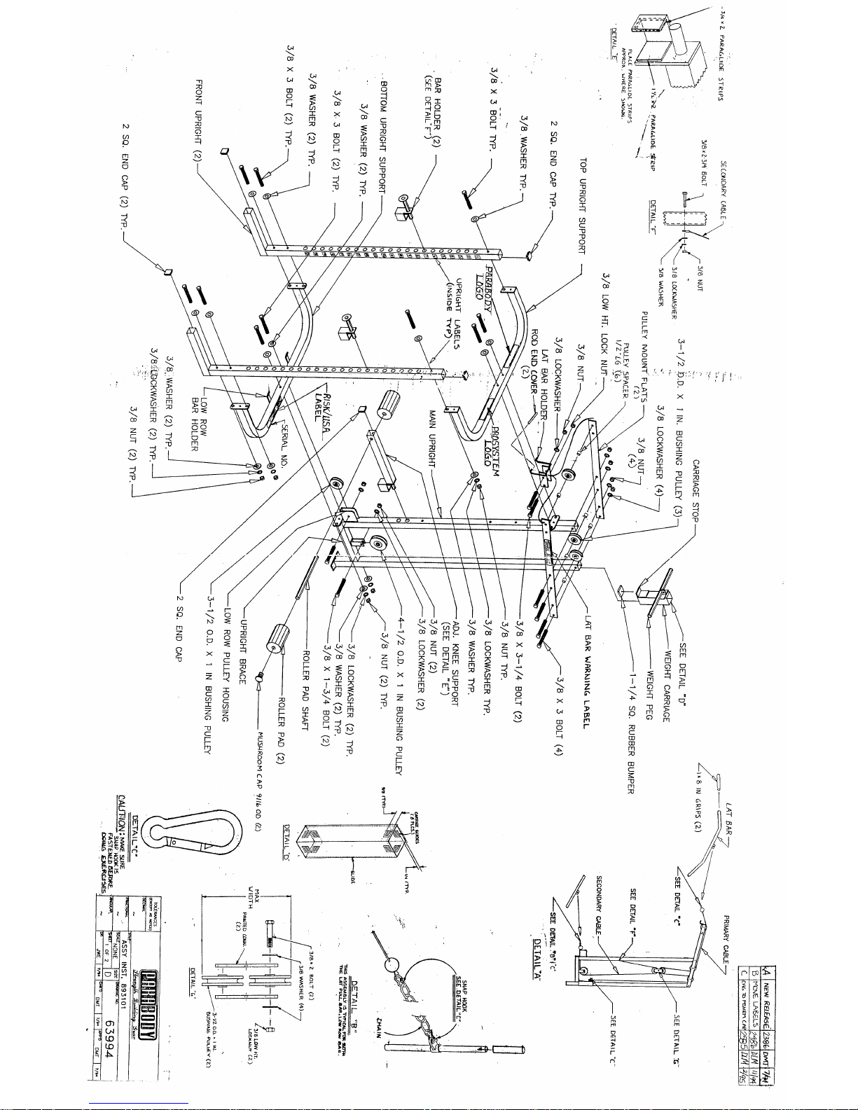
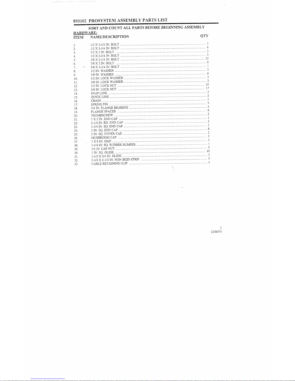
893102 PROSYSTEM ASSEMBLY PARTS LIST
SORT AND COUNTALL PARTS BEFORE BEGINNING ASSEMBLY
HARDWARE:
ITEM NAME/DESCRIPTION QTY
2.
3.
4.
5.
6.
7.
8.
9.
12.
13.
14.
15.
16.
17.
18.
19.
20.
21.
22.
23.
24.
25.
26.
27.
28.
29.
30.
31.
32.
33.
1/2X3-1/2IN.BOLT........................................................................................................ 1
i/2X3-1/4IN.BOLT........................................................................................................ 6
1/2X3IN.BOLT.............................................................................................................. 3
1/2X2-3/4.IN.BOLT........................................................................................................ 3
3/8X2-3/4IN.BOLT...................................................................................................... 12
3/8 X2 IN. BOLT.............. " ................................................................................................ 6
3/8X1-3/4IN.BOLT........................................................................................................ I
1/2IN.WASKER............................................................................................................... 3
3/8IN.WASHER............................................................................................................... 6
1/2IN.LOCKWASHER.................................................................................................... 3
3/8IN.LOCKWASHER................................................................................................. :.. 2
1/2IN.LOCKNUT.......................................................................................................... 10
3/8IN.LOCKNUT.......................................................................................................... 17
SNAPLINK....................................................................................................................... 3
QUICKLINK..................................................................................................................... 2
CHAIN............................................................................................................................... 1
SPRINGPIN.................................................................................................... : ................. 3
3/4IN.FLANGEBEARING............................................................................................... 4
FLANGESPACER..-. .......................................................................................................... 8
THUMBSCREW............................... ................................................................................. 2
3X2IN.ENDCAP........................................................................................................... 1
2-1/2IN.RD.ENDCAP.................................................................................................... 2
1-3/4IN.SQ.ENDCAP...................................................................................................... 1
2IN.SQ.ENDCAP........................................................................................................... 8
2IN.SQ.COVERCAP...................................................................................................... 2
2
MUSHROOMCAP............................................................................................................ 4
1X8IN.GRIP...................................................................................................................
1-1/4IN.SQ.RUBBERBUNfPER...................................................................................... 1
3/4IN.CAPNUT............................................................................................................... 10
1IN.SQ.GLIDE..............................................................................................................
1-1/2X3/4IN.GLIDE....................................................................................................... 3
2
5-1/2X2-1/2IN.NONSKIDSTRIP.................................................................................
CABLERETAININGCLIP............................................................................................... 4
2
12/06/95