manuals.online logo
Brands
  1. Home
  2. •
  3. Brands
  4. •
  5. Paradox
  6. •
  7. Keypad
  8. •
  9. Paradox Esprit 639 User manual

Paradox Esprit 639 User manual

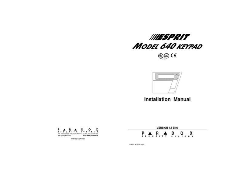
SECURITY SYSTEMS
PR DOX
780 Industrial Blvd. St-Eustache, Montreal, Quebec, Canada J7R 5V3
Fax: (514) 491-2313 http://www.paradox.ca
PRINTED IN CANADA
VERSION 1.8
ESPRIT
M
ODEL KEYPAD
639
Installation Manual
ARMED
READY
IM639 970204-0000
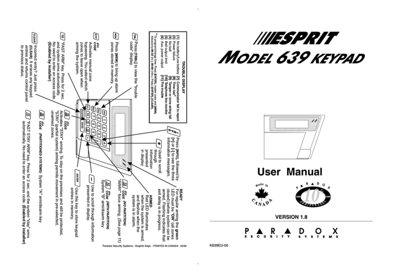
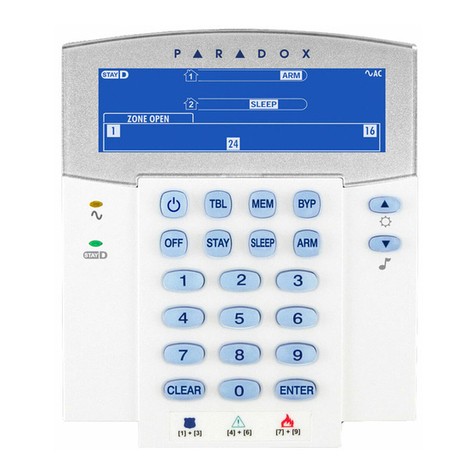
Esprit Model 639 LCD Keypad
Description
The Esprit Model 639 LCD Keypad is compatible with all Esprit
Series 8 control panels (version 3.0 onward). Standard prepro-
grammed information is presented in English, and most
installer-programmable information can be entered in the lan-
guage of your choice. The large 16-character LCD illuminated
display can be adjusted for brightness and contrast. Information
is easy to retrieve, and when correctly programmed, simple for
the end user to understand as it shows automatically all the
information you need to know about your panel.
The standard Esprit keypad layout is enhanced by the addition
of three more keys; [+], [INFO], and [-]. The [+] and [-] keys can
be used to scroll through information at sequential locations
(i.e. to scroll zones from 1-12 and 13-24). To reach zones to be
bypassed, press [2ND](i.e. if the display shows zones from 01-
12, pressing [2ND] displays zones 13-24 the
¯
indicates that
you are in the 13-24 zone display mode), pressing [2ND] again
displays zones 1-12. Enter the key numbers corresponding to
the zones you wish to "bypass". Press again on the zone key if
you wish to undo a zone selection.
When in Trbl display, pressing [2ND]provides a value for the
power supply voltage (0-255 in decimals). Multiply the value by
0.09 to get the actual power supply voltage.
Control panel programming is performed in the usual manner,
either from the keypad or from a computer, using Espload
up/downloading software. Keypad programming can be conduct-
IM639
1
ed by its own programming sections, by downloading from anoth-
er keypad or by Espload (upload/download), version 2.4 onward.
Keypad programming permits personalized information to be
entered into the LCD display. This information can include zone
descriptions, time and day of the week, and a special cus-
tomized message stored in the keypad which can then be acti-
vated by a computer download command from Espload.
(Important: The Esprit 639 LCD top view LCD display should
be installed at user eye level or lower to provide optimum dis-
play clarity and visibility.)
KEYPAD CONNECTION
The four keypad connections labeled 
RED
, 
BLACK
, 
GREEN
and

YELLOW
 should be connected to the corresponding colour termi-
nals on the control panel PC board. See the following diagram.
IM639
2
Installer Programming and End User Programming
Installer programming mode permits trained personnel to carry
out all programming functions of the 639 LCD keypad. In addition,
the end user has limited access to perform certain simple pro-
gramming functions. These functions, as well as basic program-
ming instructions, are described in a separate End User manual.
Teaching Programmed Information to Additional Keypads
A special serial cable, equipped with a 4 pin connector on each
end, is available for Esprit keypad programming. After one LCD
keypad in a system has been completely programmed, it can
be used to teach the programming to other keypads, by
means of this special cable. Complete instructions on how to
conduct this operation appear on page 18 of this manual.
Keypads can be uploaded or programmed by Espload through
a serial LCD adapter, see page 19 of this manual.
Day of the Week and Time of Day Display
Both day of the week and time of day can be viewed in the
LCD display, and are easily programmed in keypad program-
ming mode.
CUSTOM PROGRAMMING OF THE LCD KEYPAD
Installer Programming
The 639 LCD keypad contains its own microprocessor which
controls the display and other LCD display functions. This
processor operates independently of the control panel proces-
sor, and must be accessed separately, using a special Installer
Keypad Programming code.
IM639
3
The control panel should be programmed in either of the usual
ways, by means of standard keypad commands or using
Espload from a PC. (Please refer to your panel installation
manual for complete information on panel programming.)
Keypad programming must be conducted at the keypad. Once
control panel programming is complete, enter Keypad
Programming Mode in this way:
Press [CLEAR].
Press [
ENTER
] [
KEYPAD PROGRAMMING CODE
] (Default code is 0000)
A short series of beeps will be emitted by the keypad.
KEYPAD MODE SECTION: ______ appears in the display.
Enter three digits representing one of the programming
addresses, and program the required information.
Address 000 Day of the Week/Time of Day Programming
The display will read DAY: (followed by the currently pro-
grammed day of the week). The 2nd row of the display reads:
press [1] to [7]. To program the correct day, find the number
corresponding to the day of the week on the list below, and
press the single digit shown for that day, followed by [ENTER].
[1] = SUNday [5] = THUrsday
[2] = MONday [6] = FRIday
[3] = TUEsday [7] = SATurday
[4] = WEDnesday
IM639
4
Example: To program Thursday, in keypad programming
mode, at address 000, press [5] [ENTER].
After selecting the required day and pressing [ENTER], the key-
pad will advance to the time of day setting. The display now
reads TIME, followed by the currently programmed time of day.
The second row of the display reads: Enter in 24 Hrs.
To modify the time programmed, enter the four (4) digits corre-
sponding to the required time, according to the 24 hour clock.
After the 4 digits have been entered, you will hear a confirma-
tion beep, indicating that the time programmed has been auto-
matically saved in memory.
Ex.: To program 4:05 p.m, enter 16:05 by pressing [1] [6] [0] [5].
Once the correct keypad time has been programmed, press
[ENTER]. The LCD display will return to the KEYPAD MODE SEC-
TION: _____ message. Enter the next address.
IMPORTANT: Panel timeMUST ALSO be programmed.
One-key access programming can be used to set panel time.
Press [ENTER], followed by the panels installer, master or user
code 1. Press [MEM], then enter 2 digits (00 to 23) for hours,
and 2 digits (00 to 59) for minutes.
Streamline section (001-036, 100-201)
In this section, pressing [ENTER]saves the data and advances
to the next address automatically. By pressing [CLEAR], the key-
pad waits for an address: Keypad mode, Section:.
IM639
5
Address 001 - 024 Zone descriptions
Add. 001 = Zone 1 description Add. 013 = Zone 13 description
Add. 002 = Zone 2 description Add. 014 = Zone 14 description
Add. 003 = Zone 3 description Add. 015 = Zone 15 description
Add. 004 = Zone 4 description Add. 016 = Zone 16 description
Add. 005 = Zone 5 description Add. 017 = Zone 17 description
Add. 006 = Zone 6 description Add. 018 = Zone 18 description
Add. 007 = Zone 7 description Add. 019 = Zone 19 description
Add. 008 = Zone 8 description Add. 020 = Zone 20 description
Add. 009 = Zone 9 description Add. 021 = Zone 21 description
Add. 010 = Zone 10 description Add. 022 = Zone 22 description
Add. 011 = Zone 11 description Add. 023 = Zone 23 description
Add. 012 = Zone 12 description Add. 024 = Zone 24 description
Complete instructions on how to program zone description
information and other keypad messages are found below.
Special Function Keys
Entries at addresses 001 - 025 can be made in any language.
In order to enter information, the following function keys should
be used, in combination with the number keys on the keypad.
[11] Toggles between alpha and numeric modes. Ex.:
Pressing key [1] will cause the digit 1 to appear in the
display. By pressing key [11] before pressing key [1],
the keypad will switch to alpha mode and display an
a. (Pressing key [1] a second time will cause the dis-
play to show the letter b, and a third press of key [1]
will result in the letter c being displayed.)
[2ND]Toggles between UPPER and lower case on a letter.
IM639
6
[12]
If you press [12], you must enter the three digit code cor-
responding to the character or press [
CLEAR
]to exit
ASCII mode. The ASCII mode can be used to enter spe-
cial characters in the display, like asterisks, apostrophes,
arrows, etc. These characters may be chosen by entering
the three digit code corresponding to the required symbol
found in the chart on the last page of this manual.
[TRBL]Inserts a space between characters/words.
[MEM]Deletes a character.
[BYP]Deletes from the cursor position to the end of the line.
[+] Moves cursor to the right.
[-] Moves cursor to the left.
Programming Numbers in the Keypad Display
Numerals may be entered as follows:
Key [1] = 1 [2] = 2 [3] = 3 [4] = 4 [5] = 5
[6] = 6 [7] = 7 [8] = 8 [9] = 9 [10] = 0
Programming Words in the Keypad Display
Use key [11] to enter alpha mode. The letters of the alphabet
can then be programmed, according to the Alphabetical
Characters.
IM639
7
Example: Programming a Zone Description
To enter zone 7 description Patio Door, in Keypad Programming
mode, press the following keys in the order indicated.
a) [0] [0] [7] (Address for Zone 7)
b) [11] (switches to alpha mode)
c) [6] (letter p appears in display)
d) [2ND](p switches to upper case P)
e) [+] (Moves cursor one space to the right)
f) [1] (Letter A appears)
g) [2ND]A switches to lower case a
h) [+] (Moves cursor one space to the right)
i) [7] [7] (Letter t appears)
j) [+] (Moves cursor one space to the right)
k) [3] [3] [3] (Letter i appears)
l) [+] (Moves cursor one space to the right)
Alphabetical Characters
Key Press key once Press key twice Press key 3 times
[1] AB C
[2] DE F
[3] GH I
[4] JK L
[5] MN O
[6] PQ R
[7] ST U
[8] VW X
[9] YZ
IM639
8
m) [5] [5] [5] (Letter o appears)
n) [+] [+] (Cursor moves right two spaces)
o) [2] (letter d appears)
p) [2ND](d switches to upper case D)
q) [+] (Moves cursor one space to the right)
r) [5] [5] [5] (Letter O appears)
s) [2ND](O switches to lower case o)
t) [+] (Moves cursor one space to the right)
u) [5] [5] [5] (Letter o appears)
v) [+] (Moves cursor one space to the right)
w) [6] [6] [6] (Letter r appears)
x) [ENTER]
(Information is saved in memory and programming
advances to the next address.)
Address 025 Customized Message
A message with a length of up to 16 characters may be pro-
grammed at address 025, with the same character entry
method used in Zone Descriptions. This message will not
appear in the keypad display after exiting programming mode,
until the Espload command LCD MSG (LCD message) is
sent to the keypad during computer download. (Espload must
be in panel monitoring mode, and will indicate that the feature
has been activated by the message LCD message dis-
played.)
The preprogrammed message should be deactivated using
Espload. It will also be automatically deactivated when the
panel is powered down.
IM639
9
Address 026 Creating a New Installer Keypad
Programming Code
A new Installer Keypad Programming code should be created
to replace the factory default code of 0000. The new 4-digit
code permits access to keypad programming only, and must
be different from any other installer code used in the alarm sys-
tem and also different from any found on other LCD keypads in
the system.
To create an Installer Keypad Programming code, go to
address 026. The display will read KEYPAD CODE. The 2nd line
reads: NEW CODE followed by the current code. You must key
in the four digits of the new code and [ENTER]. If a 5th key is
pressed the code reverts to the original value.
Example: To create the Installer Keypad Programming code
9999, in programming mode, press [0] [2] [6], [9] [9] [9] [9],
followed by [ENTER]. The Installer Keypad Programming code is
now 9999, and programming advances to address 028.
Address 028 LCD Contrast Adjustment
At this address, the display reads Contrast Adj.00 and the 2nd
line reads: press (+, -). Press the [+] or [-] keys to increase or
decrease the contrast level as required. When the desired con-
trast level is reached, press [
ENTER
]. (The maximum contrast level
is 00, and on keypad reset, the level always reverts to 00.)
Address 029 LCD Backlight Adjustment
At this address, the first time the keypad is programmed, the dis-
play reads Backlite Adj.00 and the 2nd line shows: press (+, -).
Each time the [+] key is pressed, the number in the display will
IM639
10
change, and the display illumination level will increase. The maxi-
mum numeric reading is 07, and at this point the maximum illu-
mination is achieved. When the desired illumination level is
reached, press [
ENTER
]. Programming will advance to address 030.
Address 030 Chime Zone Selection/Keypad Mute
At address 30, the LCD message reads CHIME & MUTE and the
2nd line indicates key on = enabled. Zones 1 to 12 and key-
pad zones can be programmed on the Esprit 639 keypad.
Press the corresponding key to activate the chime zone. For
example, Key 1= chime zone 1, Key 2= chime zone 2, etc.
Chime zone is heard only when zones 1 to 12 are displayed.
Keypad zone chimes
The [TRBL]key must be pressed for the first keypad zones
chime feature to be activated, and the [2ND] key must be
pressed to activate the second keypad zones chime feature.
Keypad Mute
To mute the keypad, so that no sounds will be generated by
system activity unless keys are actually pressed, press [BYP].
(Press [BYP]again to deactivate mute feature).
Address 032 Keypad Options
At address 032, the number of keypad zones and assignment of
keypad zone numbers (1 or 2) can be selected. In addition, the
keypad zone supervision feature can be activated if required.
Desired options can be selected at address 032 by toggling on
or off necessary key(s). 
KEYPAD OPTIONS
 message appears in
the display. Second line shows 
KEY
:
ON
=
ENABLED
, if no options
IM639
11
are activated, or if options are activated, indicates which ones. The
on or off status of keys determines which keypad options are
enabled, according to the definitions found in the following table:
Address 032, key [1] KEYPAD ZONE CONNECTION
A single keypad zone (key [1] off) can be configured for
N.C. and/or N.O. contacts using 1 zone resistor (see page 23,
single keypad zone connection). Activation of ATZ keypad
zone doubling (key [1] on)reduces wiring and installation
requirements by permitting connection of two distinct zones per
input (loop) on the same pair of wires. Each zone can be
reported separately, using different resistor values. First key-
pad zone (regular zone) is identified by a 1K
W
resistor, and
second keypad zone (doubled zone) is identified by a 2.2K
W
resistor (see page 24, two keypad zones connection).
Key Feature Key light OFF Key light ON
[1] ATZ keypad zone doubling Disabled Enabled
[2] Keypad zone shown on Kpd 1 Kpd 2
keypad as Kpd1/Kpd2***
[3] Keypad zone supervision Disabled Enabled
[4] Keypad Clock mode
Refreshed by
Stand alone
panel
[5] Arming display
Panel with less Panel with more
than 12 zones than 12 zones
[6] Partitioning Disabled Enabled
[7] Operation mode Master Slave
IM639
12
Address 032, key [2] KEYPAD ZONE DISPLAY
This keys function is only applicable when key [1] is off (ATZ
zone doubling is disabled.) ***When zone doubling is dis-
abled, you can select which zone will be displayed as the key-
pad zone by the control panel. For keypad zone assignment,
refer to the following table. Activate or deactivate key [2]
according to which of the two possible keypad zones should be
reported and displayed as the keypad zone for the particular
control panel model being used.
Address 032, key [3] KEYPAD ZONE SUPERVISION
Key = on: Enable keypad zone supervision on control
panel (Address 090, key [11] on for keypad
zone 1, key [12] on for keypad zone 2) for each
keypad zone to be supervised. Refer to the panel
installation manual for further instructions.
Key = off: Disabled.
Address 032, key [4] KEYPAD CLOCK MODE
Key = on: Keypad clock runs independently.
Key = off: Keypad clock is refreshed by the panel.
Esprit panel model Kpd 1 Key [2] off Kpd 2 Key [2] on
728 Express 5 6
728 5 (no ATZ; 9(with ATZ)
6 (no ATZ; 10 (with ATZ)
738 Express 7 8
738 7 (no ATZ; 13 (with ATZ)
8 (no ATZ; 14 (with ATZ)
748 Express 13 14
748 13 14
748ES 13 14
IM639
13
Address 032, key [5] ARMING DISPLAY
Key = off: Arming display for panels with less than 12 zones.
Key = on:
Arming display for panels with more than 12 zones.
Option selection must correspond to the panel connected to
keypad.
Address 032, key [6]
CONTROL PANEL PARTITIONING
Key = off: If the control panel is armed in stay or away
mode, the display will read: STAY ARMED or SYS-
TEM ARMED.
Key = on: If control panel partitioning is enabled, when sys-
tem is armed, the display will read: A ARMED or
B ARMED or A&B ARMING.
Address 032, key [7] OPERATION MODE
This feature must only be activated with panels featuring more
than 12 zones (738, 748, 748EX, 748ES). Only one keypad can
be a master and an LED keypad must be used in mute mode.
Key = off: Master mode.
Key = on: Slave mode.
Address 034 Installer Keypad Lockout
To protect installer-programmed information in the 639 keypad
from unauthorized or accidental modification, enable the Installer
Keypad Lockout feature. When enabled, only individuals pos-
sessing the new Installer Keypad Programming code can gain
access to keypad programming mode. To erase programmed
information, enter programming address 034 and disable the
Installer Keypad Lockout feature. At address 034, the message

KEYPAD LOCK
,
PRESS
1, 4, 6
ONLY
 will appear in the LCD display.
IM639
14
Installer Keypad Lockout is enabled only when keys [1], [4] and
[6] are on at address 34, the state of the lower two rows of keys
is irrelevant. The display will read Keypad: locked. If any other
combination of keys is entered at this address, the Installer
Keypad Lockout feature is disabled. The display will read
Keypad: unlocked. If installer keypad lockout is disabled,
installer-programmed data can be erased in the following manner:
1. Place a jumper across the two pins on the bottom left side
of the back of the LCD keypad circuit board (to the left of
the bottom corner of the processor chip.)
2. Disconnect keypad from its power source.
3. Restore power to the keypad, wait until start up is finished.
4. Remove jumper.
The keypad will now automatically revert to factory default val-
ues, and all installer-programmed information from addresses
026 to 034, will be erased.
Address 036 Scrolling Delay
At this address, you can set the period of time during which a
message is displayed before the keypad advances to the next
message in the display. When you press [0] [3] [6] the display
will show: SCROLLING DELAY on the first line and DELAY: 002
SEC. on the second line. Key in desired time from 001-004 sec-
onds. After entering the 3 digit, press [ENTER]to save the value
in memory or enter a 4th digit to reset the original value.
Important: If you have more than one LCD keypad, the
scrolling delay must be the same on each one.
IM639
15
Addresses 100 - 201 Display Editing
Many of the LCD messages displayed can be edited to fit your
requirements. Enter the address corresponding to the mes-
sage to be edited, and make desired changes using the same
procedures as for zone name programming (addresses 001-
024). The following table shows a list of all available messages;
asterisks indicate empty spaces.
Address Prog. Message
100 ***Zones*Open***
101 **System*Ready**
102 ******ALARM*****
103 ***Exit*Delay***
104 **System*Armed**
105 ***Stay*Armed***
106 *Zones*Tamper***
107 *****A*Armed****
108 *****B*Armed****
109 ****A&B*Armed***
110 *Bypassing*Mode*
111 *Stay/*A*Arming*
112 *Away/*B*Arming*
113 **Bypass*Recall*
114 *Enter*Code*For*
115 Programming*Mode
116 *Alarm*in*Mem***
117 ***Press*[MEM]**
118 ****Trouble*****
119 **Power*Supply**
120 **Press*[TRBL]**
121 *Zones*Bypass***
122 Press*[BYP]+Code
123 Duress**********
Address Prog. Message
124 Address:********
125 Section:********
126 ***Clock*Mode***
127 Auto-Arming*Time
128 *Key*In*Address*
129 Streamline*Mode*
130 Enter*In*24*Hrs*
131 Press*[1]*To*[7]
132 ***Time***:*****
133 **Chime*&*Mute**
134 Contrast*Adj.***
135 Backlite*Adj.***
136 ***Press*(+,-)**
137 *****Battery****
138 **Power*Supply**
139 *****No*Bell****
140 Max*BELL*Output*
141 Max*AUX*Output
142 *Communication**
143 ***Timer*Loss***
144 *****Tamper*****
145 ***Phone*Line***
146 ****Fire*Loop***
147 Event*List*Mode*
IM639
16
Depending on the programming mode, some characters in the
previous list of messages are always used and may be over-
written. The characters are shown as # in the next table:
148 **PARADOX*LCD***
149 EMERGENCY*CALLS*
150 *****POLICE*****
151 ****AMBULANCE***
152 ******FIRE******
153 *Tel.:****-*****
154 *Tel.:****-*****
155 *Tel.:****-*****
156 ***Sun****:*****
157 ***Mon****:*****
158 ***Tue****:*****
159 ***Wed****:*****
160 ***Thu****:*****
161 ***Fri****:*****
162 ***Sat****:*****
163 ****Day*:*Sun***
164 ****Day*:*Mon
165 ****Day*:*Tue
166 ****Day*:*Wed
167 ****Day*:*Thu
168 ****Day*:*Fri
169 ****Day*:*Sat
170 Auxiliary****
171 Bell*********
172 Battery******
173 Power*Supply*
174 Fire*Loop****
175 Timer*Loss***
176 *Pwr*Sup*Lvl*
177 Disarming****
178 Arming*******
179 Alarm********
180 Restore******
181 Bypass*******
182 Tamper*******
183 Test*Report**
184 Panic********
185 Late*To*Close
186 No*Movement**
187 Partial*Arm**
188 Recent*Close*
189 Aux.*Restore*
190 Bell*Restore*
191 Batt*Restore*
192 Power*Restore
193 Fire*Restore*
194 Timer*Restore
195 Tamper*Rest.*
196 Phone*Restore
197 Phone*Line***
198 Communication
199 Alarm*Reset**
200 Prg*Espload**
201 Prg*Installer
IM639
17
Mode Original Message Characters (#)
All Section:******** Section:*****###
***Zones*Open*** ***Zones*Open###
***Time***:***** ***Time*##:##***
*Pwr*Sup*Lvl* #Pwr*Sup*Lvl#
***Sun***:****** ***Sun*##:##****
***Mon***:****** ***Mon*##:##****
***Tue***:****** ***Tue*##:##****
***Wed***:****** ***Wed*##:##****
***Thu***:****** ***Thu*##:##****
***Fri***:****** ***Fri*##:##****
***Sat***:****** ***Sat*##:##****
Bypass *Zones*Bypass*** #Zones*Bypass###
Memory *Alarm*in*Mem*** *Alarm*in*Mem###
Trouble ****Trouble***** #***Trouble**###
Teachinga Keypad Program to Another Keypad
Once the initial keypad in a system has been programmed, all
programmed information can be taught to other keypads by
doing the following:
1- Connect the special serial cable with four-pin connector to
four pins located in bottom left corner of the back of the
master or source 639 keypad. Similarly, connect the other
end of the cable to the four pins on the back of the slave or
destination 639 keypad. The master keypad requires no
other wires at this time; the slave keypad should be con-
nected to a panel.
2- The slave keypad should be in normal operating mode, not
in programming mode.
IM639
18
3- Press [ENTER] [INSTALLER KEYPAD CODE] [TRBL] on master
keypad.
4- Wait until the transfer is completed.
The programming information has now been taught to the
second keypad. Disconnect the serial cable and repeat these
steps as required for any additional keypads.
ESPLOAD UPLOAD/DOWNLOAD
This is available on Espload 2.4 onward. Refer to the following
illustration:
To program a keypad from Espload:
1. Connect cable on PC serial port to DB-9 female of LCD
adapter.
2. Connect special serial cable of the keypad between the key-
pad and LCD adapter (keypad must be in normal mode).
3. To download information to a keypad, set the keypad in nor-
mal mode. Press F4 after all messages have been pro-
grammed and select full download.
IM639
19
[STAY]Cancel communication attempts
(master code and user 1 can only stop calls to Espload),
(installer code - all communications)
Info Mode
If the [INFO] key is pressed, Emergency Calls will be dis-
played. Three emergency messages can be programmed
(addresses 150 to 155). follow the Display Editing procedures
to edit these messages.
Each emergency message consists of 2 lines containing 16
characters. Addresses are paired as follows:
Message #1: Addresses 150 and 153.
Message #2: Addresses 151 and 154.
Message #3: Addresses 152 and 155.
Enter the first line of the emergency message in the first address
and the second line of the message in the second address.
Power supply failure
The LCD display will alternate between:TROUBLE POWER SUP-
PLY and system status messages.
Power supply level
In normal mode, press
[
TRBL
]then
[2ND], multiply the decimal
value on the LCD display by 0.09 to get the exact power sup-
ply voltage level.
Viewing the event list (view event list mode)
In normal mode, pressing [MEM], followed by [INFO]switches
IM639
21
4. Use Espload software to download information to keypad. To
upload keypad, press F4 and select full upload (in Espload
software), enter into keypad programming and press [TRBL].
Key access programming
Several control panel features can be quickly programmed on
the keypad, without entering any programming addresses or
section numbers. Select one-key access programming by
pressing [ENTER], followed by the Installer code. Then press a
single key (from the following list) corresponding to the feature
you want to activate:
[MEM]Panel time and clear "trouble 8" (all 3 codes)
Enter two digits (00 to 23) for hours + 2 digits (00 to 59)
for minutes.
[BYP]Test report (all 3 codes)
Reporting is enabled at address 086 keys [11],[12]. A
value must be entered at address 512, and both tele-
phone and account numbers must be programmed.
[TRBL]Call Espload via telephone (all 3 codes)
Panel ID (addresses 004-005) and PC password num-
bers (addresses 006-007) and PC download phone
number (addresses 008-015) must be programmed.
[AWAY]Answer Espload (all 3 codes)
This feature is available when using the ADP-1 adapter.
In Espload, "blind dial" must be activated in "modem
setup" section, and panel phone number programmed
(works also without ADP-1).
IM639
20
IM639
23
the system to view event list mode. The display will indicate:
Event/Event number/Day/Time ex: ALARM 01A (1st line) / 001
Sun 12:52 (2nd line).
Pressing [+] starts from the current to the oldest event and
pressing [-] starts from the current to the most recent event.
Autoscrolling is started by pressing [+] or [-] for 2 seconds. You
have an adjustable delay (1 to 4 seconds) between each events
in autoscrolling (same as the scrolling delay, address 036).
When you reach the end of the event buffer, a beep is heard.
Autoscrolling is turned off by pressing again on [+] or [-]. If an
unlisted event occurs or there are no more events in the event
list, a fail beep is heard and not listed is displayed on the LCD.
Important: If timer loss message appears in the display, the time
and day indicated may not be accurate. If the time was repro-
grammed following power loss, all messages displayed before
timer restore message contain the correct time and day.
IM639
22
IM639
25
IM639
24
IMPORTANT
This security system should undergo frequent testing.
However, despite regular testing, and due to, but not
limited to, criminal tampering or electrical disruption, it is
possible for this product to fail to perform as expected.
WARRANTY
Warranty conditions for the Esprit may vary from
country to country. Please consult your local dealer for
complete warranty information. In all cases, the war-
ranty does not cover malfunctions arising from
installer error or failure to follow installation/operation
instructions, nor does it apply to damages due to
causes beyond the control of Paradox Security
Systems, such as lightning, excessive voltage,
mechanical shock or water damage.
LIABILITY
Under no circumstances shall Paradox Security
Systems be held liable for any direct or indirect dam-
ages, loss of anticipated profits, loss of time or any other
losses incurred by the buyer in connection with the pur-
chase, installation, operation or failure of this product.
IM639

Other manuals for Esprit 639

2

Other Paradox Keypad manuals

Paradox Digiplex EVO DGP2-641BL User manual

Paradox

Paradox Digiplex EVO DGP2-641BL User manual

Paradox K35 User manual

Paradox

Paradox K35 User manual

Paradox Spectra 1689 User manual

Paradox

Paradox Spectra 1689 User manual

Paradox Digiplex DGP2-641 User manual

Paradox

Paradox Digiplex DGP2-641 User manual

Paradox DigiplexNE DGP2-641 User manual

Paradox

Paradox DigiplexNE DGP2-641 User manual

Paradox Digiplex DGP-620 Assembly instructions

Paradox

Paradox Digiplex DGP-620 Assembly instructions

Paradox K70C User manual

Paradox

Paradox K70C User manual

Paradox Grafica DNE-K07 Operating instructions

Paradox

Paradox Grafica DNE-K07 Operating instructions

Paradox Digiplex EVO DGP2-641BL User manual

Paradox

Paradox Digiplex EVO DGP2-641BL User manual

Paradox IMPERIAL V32 User manual

Paradox

Paradox IMPERIAL V32 User manual

Paradox K656 Touch Sense User manual

Paradox

Paradox K656 Touch Sense User manual

Paradox K32LCD+ User manual

Paradox

Paradox K32LCD+ User manual

Paradox TM50 Touch User manual

Paradox

Paradox TM50 Touch User manual

Paradox K32LCD Troubleshooting guide

Paradox

Paradox K32LCD Troubleshooting guide

Paradox K641+ User manual

Paradox

Paradox K641+ User manual

Paradox 1686V User manual

Paradox

Paradox 1686V User manual

Paradox Spectra 1641 Assembly instructions

Paradox

Paradox Spectra 1641 Assembly instructions

Paradox DGP2-641 User guide

Paradox

Paradox DGP2-641 User guide

Paradox Digiplex DGP2-648 User manual

Paradox

Paradox Digiplex DGP2-648 User manual

Paradox Magellan MG32LRF Service manual

Paradox

Paradox Magellan MG32LRF Service manual

Paradox Esprit User manual

Paradox

Paradox Esprit User manual

Paradox K641 User manual

Paradox

Paradox K641 User manual

Paradox 1686V User manual

Paradox

Paradox 1686V User manual

Paradox Esprit+ 642 Assembly instructions

Paradox

Paradox Esprit+ 642 Assembly instructions

Popular Keypad manuals by other brands

Velux WLI 110 installation instructions

Velux

Velux WLI 110 installation instructions

Abus FUBE35000A manual

Abus

Abus FUBE35000A manual

Russound ST2-KP instruction manual

Russound

Russound ST2-KP instruction manual

urmet domus mikra 1086 Installation handbook

urmet domus

urmet domus mikra 1086 Installation handbook

Rosslare AC-F4 Series Installation and programming manual

Rosslare

Rosslare AC-F4 Series Installation and programming manual

NAPCO Magnum Alert RP2000LCD installation instructions

NAPCO

NAPCO Magnum Alert RP2000LCD installation instructions

Speco SG-100 Specifications

Speco

Speco SG-100 Specifications

Crestron CN-WP12FW Operation guide

Crestron

Crestron CN-WP12FW Operation guide

Xantech 598 installation instructions

Xantech

Xantech 598 installation instructions

Conlan C1000LP manual

Conlan

Conlan C1000LP manual

GE NX-148E - Security NetworX LCD Keypad user manual

GE

GE NX-148E - Security NetworX LCD Keypad user manual

Leroy-Somer Nidec Field RTC Keypad Installation and connections

Leroy-Somer

Leroy-Somer Nidec Field RTC Keypad Installation and connections

B&D tri-tran 062269 installation instructions

B&D

B&D tri-tran 062269 installation instructions

Mhouse DS1 easy instructions

Mhouse

Mhouse DS1 easy instructions

Helmer Horizon series user guide

Helmer

Helmer Horizon series user guide

Bewator M43 Installation note

Bewator

Bewator M43 Installation note

WEG HMI-03 user manual

WEG

WEG HMI-03 user manual

IEI Technology prox.pad Installation & programming manual

IEI Technology

IEI Technology prox.pad Installation & programming manual

manuals.online logo
manuals.online logoBrands
  • About & Mission
  • Contact us
  • Privacy Policy
  • Terms and Conditions

Copyright 2025 Manuals.Online. All Rights Reserved.