PASCO PAS Port PS-2103A User manual

®
Instruction Sheet
012-09625B
Motion Sensor
PS-2103A
+1 916-786-3800
Quick Start
1. Connect the Motion Sensor to your PASPORT-compatible
interface (such as the 850 Universal Interface or the SPARK
Science Learning System).
2. If you are using a computer, connect the PASCO interface to
it and start the data acquisition software (such as PASCO
Capstone or SPARKvue).
3. Place an object in front of the sensor at least 15 cm away.
4. Click “Record” or press “Start to begin recording data.
5. Move the object in a straight line directly away from or
toward the sensor.
Introduction
The PS-2103A Motion Sensor works with your PASCO interface
to measure and record position, velocity, and acceleration. It pro-
duces a series of ultrasonic pulses and detects the sound reflect-
ing back from an object in front of it. The interface measures the
times between outgoing pulses and returning echoes. From these
measurements, it determines the position, velocity, and accelera-
tion of the object.
This instruction sheet includes procedures for setting up the hard-
ware and software collecting data, changing the sample rate, cali-
brating the sensor, mounting the sensor on equipment, and
troubleshooting.
Theory of operation is described and specifications are listed at
the end of these instructions.
Note: Essential PASCO Capstone, SPARK SLS, and GLX tasks are
described briefly in this instruction sheet. For more information, refer to
the User’s Guide or the on-line help for the interface and/or the data acqui-
sition software.
Included Equipment Part Number
Motion Sensor PS-2103A
Additional Equipment Required
PASPORT-compatible Interface See PASCO catalog
or www.pasco.com
PASPORT Plug
Range
Switch
Ultrasonic
Transducer
Rotating
Head
Clips for
mounting
on track Hole for
mounting
on rod
Target
Indicator

®
Motion Sensor PS-2103A
2
Set-up
To Connect to a PASPORT-compatible Inter-
face
1. Connect the Motion Sensor's plug to a PASPORT input port
of your PASCO interface.
2. Turn on the interface. If you are using a computer, connect
the interface to it and start the data acquisition software.
PASCO Capstone
• PASCO Capstone will automatically prepare itself for data
collection. In the software, click the “Hardware Setup” icon
in the Tools palette to open the Hardware Setup panel.
• Confirm that the panel shows the icon of the Motion Sensor
connected to the icon of the interface.
• To create a graph display, double click a choice in the work-
book page, or drag the Graph icon from the Displays palette
to the workbook page.
SPARK Science Learning System (SLS)
• When the sensor is connected to a SPARK SLS, the screen
shows a list of the sensor’s parameters (such as position,
velocity, and acceleration).
• Press a measurements and then press the “Show” icon to cre-
ate a graph display.
Xplorer GLX
• The Xplorer GLX automatically detects the Motion Sensor
and opens a graph display of position on the vertical axis and
time on the horizontal axis.
PASPORT Input Port
Sensor
Plug
Alignment Tab
Motion Sensor icon
850 Universal Interface icon
PASCO Capstone
Hardware Setup Panel
Graph icon
Create a Graph Display
(1) Press a
measurement
(2) Press
“Show”
SPARKvue Motion
Sensor Screen
SPARKvue
Graph Display

®
Motion Sensor PS-2103A
3
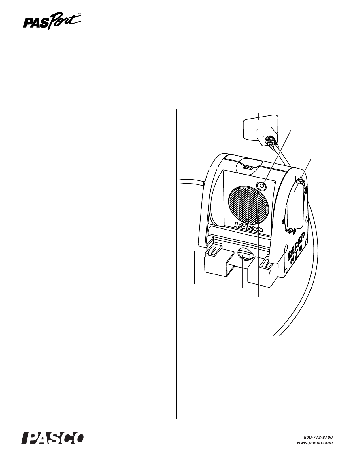
To Aim the Motion Sensor at an Object
1. Set the range switch to the short range ( ) or long
range ( ) setting.
• Select for measuring a cart on a track.
• Select for measuring most other objects.
2. Arrange the Motion Sensor and object so that the Motion
Sensor's transducer faces the object.
• The object should be at least 15 cm from the transducer.
• If the object will move, it should move directly toward
or away from the Motion Sensor.
• Aim the motion sensor slightly up to avoid detecting the
tabletop.
3. Remove objects that may interfere with the measurement.
These include objects between the sensor and target object,
either directly in front of the sensor or to the sides.
Data Collection
PASCO Capstone
1. Click Record.
The Motion Sensor starts clicking. If a target is in range, the
target indicator flashes with each click. PASCO Capstone
starts collecting and displaying data.
2. Click Stop to stop data collection.
SPARK SLS
1. Press Start to begin collecting and recording data.
2. Press Stop to end data collection.
Xplorer GLX (Standalone)
1. Press s.
The Motion Sensor starts clicking. If a target is in range, the
target indicator flashes with each click. The GLX starts
collecting and displaying data.
2. Click sto stop data collection.
3. Click sagain to start recording data in a new data run.
Sensor Configuration
To View Velocity and Acceleration
The Position measurement appears by default. You can also
enable Velocity and Acceleration measurements.
• In the PASCO Capstone graph, click the label of the vertical
axis and select Velocity or Acceleration from the Measure-
ments Menu.
• In the SPARKvue graph, press the Graph Tools icon to open
the Graph Tools palette. Press the Display Properties icon to
open the Line Graph Properties screen. Press Velocity or
Acceleration and then press OK.
• On the GLX while viewing any display screen, press c
twice to open a data source menu. Select More to expand the
menu. Select Velocity or Acceleration.
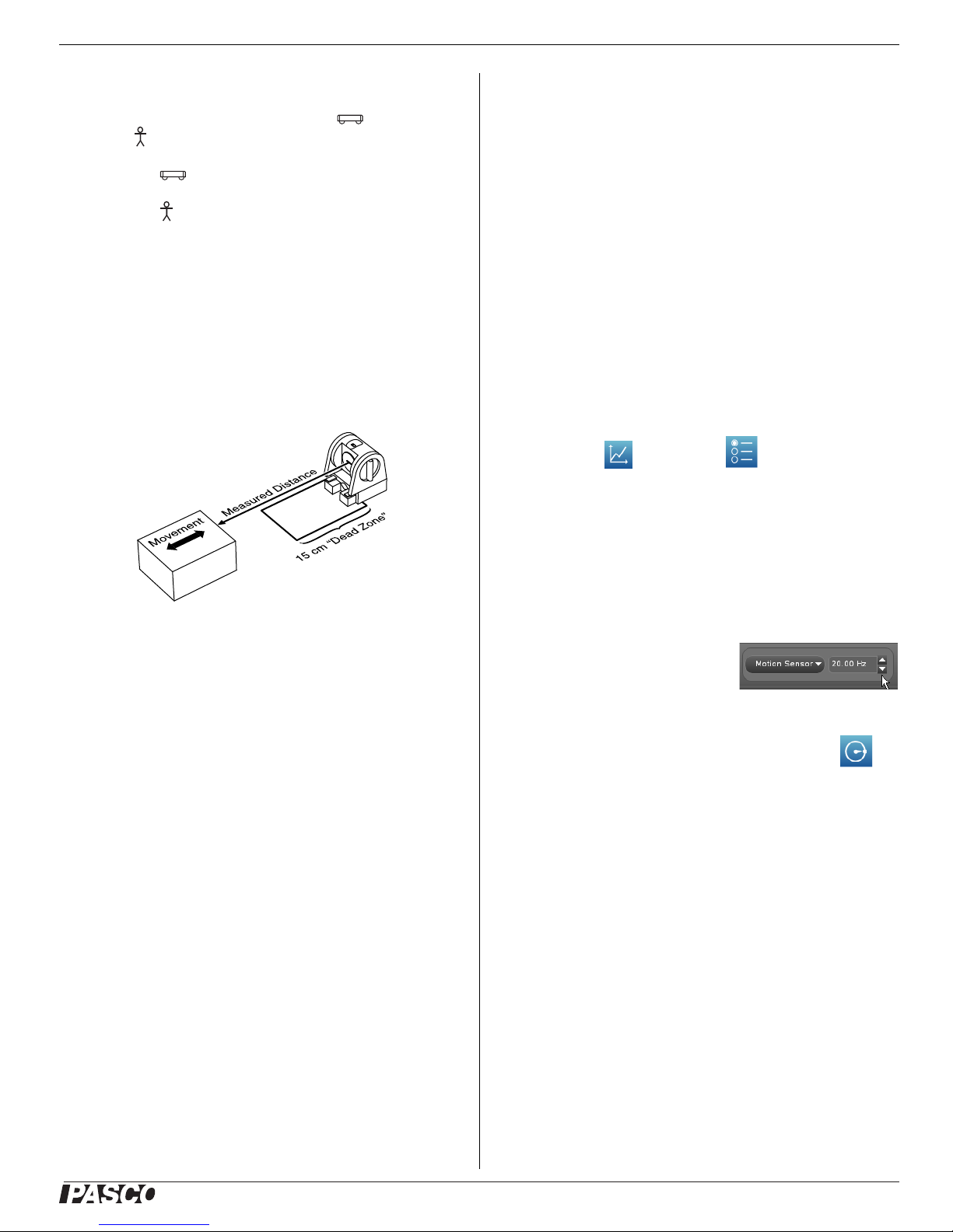
To Change the Sample Rate
• In PASCO Capstone, change the
Motion Sensor sampling rate by
clicking the up or down arrows
in the Sample Rate Control tool.
• In SPARKvue, press the Sampling Options
icon. Select the Sampling Mode, Sample
Rate, and Sample Rate Unit in the Sampling
Options screen, and then press OK.
• On the GLX, press h+ Ito open the Sensors screen.
Highlight the Sample Rate setting and press +or -.
The normal range of sampling rates is between 1 Hz and 50 Hz.
At the default rate, the Motion Sensor can measure distance up to
8 m. The maximum distance decreases with increasing sample
rate. At very high sample rates (between 50 Hz and 250 Hz), the
maximum distance is less than 2 m.
Display
Properties icon
Graph
Tools icon
Motion Sensor
Sample Rate
Sampling
Options icon

®
Motion Sensor PS-2103A
4
Equipment Mounting
Mount the Motion Sensor as illustrated on a vertical rod (a) or a
horizontal rod (b).
Integrated clips allow it to be attached to the end of a dynamics
track (c).
A threaded hole in the bottom of the unit (d) is provided for
attachment to the PS-2546 Magnetic Bracket (e), the ME-6743
Cart Adapter (f), and other 1/4-20 threaded mounting devices
such as a camera tripod.
To protect the Motion Sensor from being hit by an object, use a
device such as the SE-7256 Motion Sensor Guard (g) or
ME-9806 bracket with a rubber band (h). The Motion Sensor can
“see through” a wire screen or rubber band placed close to the
transducer.
Troubleshooting
If the Motion Sensor fails to perform satisfactorily, try these
steps:
• Ensure that the target object is no closer than 15 cm.
• Switch the range switch to the other setting.
• Adjust the aim left, right, up, or down. In some cases the
Motion Sensor works best when it is aimed slightly to the
side or above the target in order to exclude interfering
objects.
• Improve the target by adding a larger or harder surface to
reflect ultrasound. A small object can be a better reflector
than large object if it has a harder surface.
• Remove interfering objects near the target object or sensor.
• Increase or decrease the sample rate.
Theory of Operation
The Motion Sensor uses an electrostatic transducer as both a
speaker and a microphone. For each sample, the transducer trans-
mits a burst of 16 ultrasonic pluses with a frequency of about 49
kHz. This burst of pulses can be heard as a single click. The ultra-
sonic pulses reflect off an object and return to the sensor. The tar-
get indicator on the sensor flashes when the transducer detects an
echo.
Sound intensity decreases with distance; to compensate, the sen-
sor increases the gain of the receiver amplifier as it waits for the
echo. The increased gain allows the sensor to detect an object up
to 8 m away. The lower gain at the beginning of the cycle reduces
the circuit's sensitivity to echoes from false targets.
The sensor measures the time between the trigger rising edge and
the echo rising edge. It uses this time and the speed of sound to
calculate the distance to the object. To determine velocity, it uses
consecutive position measurements to calculate the rate of
change of position. Similarly, it determines acceleration using
consecutive velocity measurements.
(a)
(b)
(c)
(d)
(e)
(f)
(g) (h)

®
Motion Sensor PS-2103A
5
Specifications
Technical Support
For assistance with any PASCO product, contact PASCO at:
Limited Warranty For a description of the product warranty, see the
PASCO catalog.
Copyright The PASCO scientific 012-09625B Motion Sensor Instruction
Sheet is copyrighted with all rights reserved. Permission is granted to
non-profit educational institutions for reproduction of any part of this man-
ual, providing the reproductions are used only in their laboratories and
classrooms, and are not sold for profit. Reproduction under any other cir-
cumstances, without the written consent of PASCO scientific, is prohibited.
Trademarks PASCO, PASCO scientific, PASPORT, SPARK Science
Learning System, SPARKvue, and Xplorer GLX are trademarks or regis-
tered trademarks of PASCO scientific, in the United States and/or in other
countries. All other brands, products, or service names are or may be
trademarks or service marks of, and are used to identify, products or ser-
vices of, their respective owners. For more information visit
www.pasco.com/legal.
Product End of Life Disposal Instructions:
This electronic product is subject to disposal and recycling regu-
lations that vary by country and region. It is your responsibility to
recycle your electronic equipment per your local environmental
laws and regulations to ensure that it will be recycled in a manner
that protects human health and the environment. To find out
where you can drop off your waste equipment for recycling,
please contact your local waste recycle/disposal service, or the
place where you purchased the product.
The European Union WEEE (Waste Elec-
tronic and Electrical Equipment) symbol (to
the right) and on the product or its packag-
ing indicates that this product must not be
disposed of in a standard waste container.
Minimum Range 15 cm
Maximum Range 8 m
Transducer Rotation 360°
Range Settings Short Range: for distance measurement up
to 2 m with improved rejection of false target
signals and air-track noise
Long Range: for distance measurement up
to 8 m
Mounting Options • On rod up to 12.7 mm diameter
• Directly to PASCO dynamics tracks
• On table top
Address: PASCO scientific
10101 Foothills Blvd.
Roseville, CA 95747-7100
Phone: +1 916-786-3800 (worldwide)
800-772-8700 (U.S.)
Web: www.pasco.com
Email: suppo[email protected]
Table of contents
Other PASCO Accessories manuals

PASCO
PASCO Pasport PS-2111 User manual

PASCO
PASCO PS-3202 Guide

PASCO
PASCO PASPORT PS-2177 User manual

PASCO
PASCO PS-3213 User manual

PASCO
PASCO PS-3228 User manual

PASCO
PASCO PasPort PS-2106A User manual

PASCO
PASCO PS-3208 Guide

PASCO
PASCO AirLink PS-3200 User manual

PASCO
PASCO Pasport PS-2110 User manual

PASCO
PASCO PAS Port PS-2186 User manual

PASCO
PASCO UI-5101 User manual

PASCO
PASCO PS-2102 User manual

PASCO
PASCO PS-3227 Guide

PASCO
PASCO PS-3216 User manual

PASCO
PASCO PS-3208 User manual

PASCO
PASCO PS-3204 User manual

PASCO
PASCO ME-9838 User manual

PASCO
PASCO PS-3219 User manual

PASCO
PASCO PasPort PS-2195 User manual

PASCO
PASCO PASPort PS-2129 User manual