PI M-126 User manual

PI miCos GmbH, Freiburger Strasse 30, 79427 Eschbach, Germany
Phone +49 7634 5057-0, Fax +49 7634 5057-99, Email info@pimicos.com, www.pi.ws
MP42E
M
-126 Precision Microtranslation Stage
User Manual
Version: 3.0.0
Date: 20.01.2021
This document describes the following precision
micropositioning stages:
M-126.CG1, M-126.DG1:
With DC gear motor, rotary encoder
M-126.PD1, M-126.PD2:
With ActiveDrive DC motor, rotary encoder
M-126.2S1:
With 2-phase stepper motor
M-126.M0
For manual operation

The following company names and brands are registered trademarks of Physik Instrumente (PI) GmbH & Co.
KG:
PI®, NanoCube®, PICMA®, PILine®, NEXLINE®, PiezoWalk®, NEXACT®, Picoactuator®, PInano®, PIMag®,
Q-Motion®
The patents held by PI are found in our patent list: https://www.physikinstrumente.com/en/about-pi/patents
Notes on brand names and third-party trademarks:
BiSS is a registered trademark of iC-Haus GmbH.
© 2020 Physik Instrumente (PI) GmbH & Co. KG, Karlsruhe, Germany. The text, photographs, and drawings in
this manual are protected by copyright. With regard thereto, Physik Instrumente (PI) GmbH & Co. KG retains
all the rights. The use of any text, images and drawings is permitted only in part and only when indicating the
source.
Original instructions
First printing: 20.01.2021
Document number: MP42E, ASt, Version 3.0.0
Subject to change. This manual is superseded by any new release. The latest respective release is available for
download (p. 3) on our website.

1About this Document 1
1.1 Objective and Target Audience of this User Manual.................................................. 1
1.2 Symbols and Typographic Conventions...................................................................... 1
1.3 Definition of Terms..................................................................................................... 2
1.4 Figures ........................................................................................................................ 2
1.5 Other Applicable Documents ..................................................................................... 3
1.6 Downloading Manuals................................................................................................ 3
2Safety 5
2.1 Intended Use .............................................................................................................. 5
2.2 General Safety Instructions ........................................................................................ 5
2.3 Organizational Measures............................................................................................ 5
3Product Description 7
3.1 Model Overview ......................................................................................................... 7
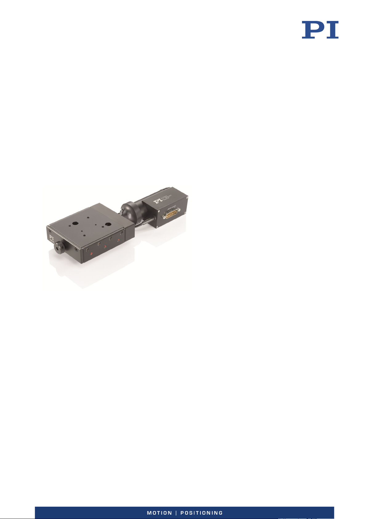
3.2 Product View .............................................................................................................. 8
3.3 Direction of Motion.................................................................................................... 9
3.4 Product Labeling....................................................................................................... 10
3.5 Scope of Delivery...................................................................................................... 11
3.6 Accessories ............................................................................................................... 11
3.7 Suitable Controllers .................................................................................................. 12
3.8 Technical Features.................................................................................................... 12
3.8.1 Encoder........................................................................................................ 12
3.8.2 Limit switches .............................................................................................. 12
3.8.3 Reference Switch......................................................................................... 12
3.8.4 Integrated PWM Amplifier .......................................................................... 13
4Unpacking 15
5Installation 17
5.1 General Notes on Installing ...................................................................................... 17
5.2 Turning the Connectors of the M-126...................................................................... 18
5.3 Mounting the M-126 onto a Surface........................................................................ 19
5.4 Fixing the Load to the M-126 ................................................................................... 20
5.5 Connecting the M-126 to the Controller.................................................................. 21
5.6 Connecting the Power Supply to the M-126 ............................................................ 22
6Startup 23
6.1 General Notes on Startup......................................................................................... 23
Contents

6.2 Starting and Operating the M-126 ........................................................................... 23
7Maintenance 27
7.1 General Notes on Maintenance ............................................................................... 27
7.2 Doing a Maintenance Run ........................................................................................ 27
7.3 Cleaning the M-126 .................................................................................................. 28
8Troubleshooting 29
8.1 Possible Causes and Correction................................................................................ 29
9Customer Service 31
10 Technical Data 33
10.1 Specifications............................................................................................................ 33
10.1.1 Data Table.................................................................................................... 33
10.1.2 Maximum Ratings........................................................................................ 35
10.1.3 Ambient Conditions and Classifications ...................................................... 35
10.1.4 Limit Switch Specifications .......................................................................... 36
10.1.5 Reference Switch Specifications.................................................................. 36
10.2 Dimensions ............................................................................................................... 37
10.2.1 M-126 .......................................................................................................... 37
10.2.2 Optional Accessories ................................................................................... 42
10.3 Pin Assignment ......................................................................................................... 44
10.3.1 D-sub 15 (m) Controller Connection............................................................ 44
10.3.2 Mini XLR3 (m) Power Supply Connection .................................................... 46
11 Old Equipment Disposal 47
12 EU Declaration of Conformity 49

1 About this Document
M-126 Precision Microtranslation Stage MP42E Version: 3.0.0 1
1.1 Objective and Target Audience of this User Manual
This manual contains information on using the M-126 as intended.
It assumes that the reader has a fundamental understanding of basic servo systems as well as
motion control concepts and applicable safety procedures.
The latest versions of the user manuals are available for download (p. 3) on our website.
1.2 Symbols and Typographic Conventions
The following symbols and typographic conventions are used in this user manual:
CAUTION
Dangerous situation
Failure to comply could lead to minor injury.
Precautionary measures for avoiding the risk.
NOTICE
Dangerous situation
Failure to comply could cause damage to equipment.
Precautionary measures for avoiding the risk.
INFORMATION
Information for easier handling, tricks, tips, etc.
Symbol/
Label
Meaning
1.
2.
Action consisting of several steps whose sequential
order must be observed
Action consisting of one or several steps whose
sequential order is irrelevant
List item
1
About this Document

1 About this Document
2 Version: 3.0.0 MP42E M-126 Precision Microtranslation Stage
Symbol/
Label
Meaning
p. 5 Cross-reference to page 5
RS-232 Labeling of an operating element on the product
(example: socket of the RS-232 interface)
Warning sign on the product which refers to detailed
information in this manual.
1.3 Definition of Terms
Term Explanation
Load Capacity Maximum load capacity in the vertical direction when the positioner
is mounted horizontally. The contact point of the load is at the center
of the platform.
Max. push/pull force Maximum force in the direction of motion. Some positioners may
have higher forces but this could limit the lifetime.
Incremental position
sensor
Sensor (encoder) for detecting changes of position or changes of
angle. Signals from the incremental position sensor are used for axis
position feedback. After the controller is switched on, referencing
must be done before absolute target positions can be commanded
and reached.
Pulse width modulation
(PWM)
PWM-controlled motors allow control of the motor performance with
a high-frequency-signal. This means that the power signal can be
separated from the digital control signal.
1.4 Figures
For better understandability, the colors, proportions, and degree of detail in illustrations can
deviate from the actual circumstances. Photographic illustrations may also differ and must not
be seen as guaranteed properties.

1 About this Document
M-126 Precision Microtranslation Stage MP42E Version: 3.0.0 3
1.5 Other Applicable Documents
The devices and software tools from PI mentioned in this documentation are described in
separate manuals.
Product Document
Positioners with Electric Motors MP119EK Short Instructions
C-863.12 Mercury Controller MS251 User Manual
C-884.xDC DC Motor Controller MS243 User Manual
C-663.12 Mercury Step Stepper Motor Controller MS241 User Manual
1.6 Downloading Manuals
INFORMATION
If a manual is missing or problems occur with downloading:
Contact our customer service department (p. 31).
Downloading Manuals
1. Open the website www.pi.ws.
2. Search the website for the product number (e.g., P-882) or the product family (e.g.,
PICMA® bender).
3. Click the corresponding product to open the product detail page.
4. Click the Downloads tab.
The manuals are shown under Documentation. Software manuals are shown under
General Software Documentation.
5. Click the desired manual and fill out the inquiry form.
The download link will then be sent to the email address entered.


2 Safety
M-126 Precision Microtranslation Stage MP42E Version: 3.0.0 5
2.1 Intended Use
The M-126 is a laboratory device as defined by DIN EN 61010. It is intended for indoor use and
use in an environment that is free of dirt, oil and lubricants.
In accordance with its design, the M-126 is intended for single-axis positioning, adjusting and
shifting of loads at different velocities. The M-126 is not intended for applications in areas
where failure could lead to considerable risk to people or the environment.
The M-126 is intended for horizontal or vertical mounting. For the load limits with vertical
mounting, see "General Notes on Installation" (p. 17).
It is only possible to use the M-126 as intended when completely mounted and connected.
The M-126 must be operated with a suitable controller (p. 12). The controller is not included in
the scope of delivery of the M-126.
2.2 General Safety Instructions
The M-126 is built according to state-of-the-art technology and recognized safety standards.
Improper use can result in personal injury and/or damage to the M-126.
Use the M-126 for its intended purpose only, and only when it is in perfect technical
condition.
Read the user manual.
Eliminate any malfunctions that may affect safety immediately.
The operator is responsible for the correct installation and operation of the M-126.
2.3 Organizational Measures
User manual
Always keep this user manual together with the M-126.
The latest versions of the user manuals are available for download (p. 3) on our
website.
Add all information from the manufacturer to the user manual, for example
supplements or technical notes.
If you give the M-126 to a third party, include this user manual as well as other relevant
information provided by the manufacturer.
2
Safety

2 Safety
6 Version: 3.0.0 MP42E M-126 Precision Microtranslation Stage
Do the work only if the user manual is complete. Missing information due to an
incomplete user manual can result in minor injury and damage to equipment.
Install and operate the M-126 only after you have read and understood this user
manual.
Personnel qualification
The M-126 may only be installed, started, operated, maintained, and cleaned by authorized and
appropriately qualified personnel.

3 Product Description
M-126 Precision Microtranslation Stage MP42E Version: 3.0.0 7
3.1 Model Overview
Product number Description
M-126.CG1 Microtranslation stage, 25 mm travel range, compact DC gear motor
M-126.DG1 Microtranslation stage, 25 mm travel range, DC gear motor
M-126.PD1 Microtranslation stage, 25 mm travel range, ActiveDrive DC motor,
including 24 V power adapter
M-126.PD2 Microtranslation stage, 20 mm travel range, ActiveDrive DC motor, ball
screw, including 24 V power adapter
M-126.2S1 Microtranslation stage, 25 mm travel range, 2-phase stepper motor
M-126.M0 Microtranslation stage, 25 mm travel range, manual
For further technical data, see the specifications (p. 33).
3
Product Description

3 Product Description
8 Version: 3.0.0 MP42E M-126 Precision Microtranslation Stage
3.2 Product View
Figure 1: Elements of the M-126 with electric drive, example: M-126.DG1
1. Base body with platform
2. Motor
3. Connectors (controller, for M-126.PDx additionally: supply voltage)
4. Rotary knob of the drive screw for moving the platform by hand

3 Product Description
M-126 Precision Microtranslation Stage MP42E Version: 3.0.0 9
3.3 Direction of Motion
Figure 2: Direction of motion of the M-126
Arrow direction: Direction of motion on positive (+) and negative (-) command

3 Product Description
10 Version: 3.0.0 MP42E M-126 Precision Microtranslation Stage
3.4 Product Labeling
Figure 3: Position of the product labeling
1. Manufacturer's logo
2. Product name, serial number, Manufacturer's address (website)
3. Connection label

3 Product Description
M-126 Precision Microtranslation Stage MP42E Version: 3.0.0 11
3.5 Scope of Delivery
The following items are supplied with the M-126 according to your order:
M-126.CG1, .DG1, .PDx models
Item number Component
000011348 Screw set for mounting the positioner and the load
6 socket head screws, M4×18 ISO 4762
Hex key, AF 3
MP119EK Short instructions for positioners with electric motors
Additionally for the M-126.PDx models:
Item number Component
C-501.24050H Wide input range power supply 24 V DC / 50 W
3763 Power cord
K050B0002 Adapter from 5.5 mm x 2.1 mm barrel connector to mini XLR3 (f) for the
power adapter connector
M-126.M0 model
Item number Component
2490 Screw set for mounting the positioner and the load
4 socket head screws, M4×20 ISO 4762
Hex key, AF 3
3.6 Accessories
The following articles are not in the scope of delivery of the M-126 and must be ordered
separately, if required.
Order number Description
M-126.80 Adapter plate for mounting M-126 stages onto honeycomb platforms
(metric and inches)
M-125.90 Vertical mounting bracket for M-126
To order, contact our customer service department (p. 31).

3 Product Description
12 Version: 3.0.0 MP42E M-126 Precision Microtranslation Stage
3.7 Suitable Controllers
The version of the M-126 with electric drive must be connected to a suitable controller. The
following controllers from PI are suitable for operating the M-126:
Models Controller
M-126.XG1, M-126.PDx C-863, C-884
M-126.2S1 C-663
The required PC software is included in the scope of delivery of the controllers from PI.
Operating the controllers is described in the corresponding user manuals.
Note that the cables required for connecting the M-126 to the controller and the required
adapter must be ordered separately.
To order, contact our customer service department (p. 31).
3.8 Technical Features
3.8.1 Encoder
The M-126.XG1 and M-126.PDs models are equipped with an incremental rotary encoder.
A rotary encoder is implemented at a rotating point in the drivetrain, e.g., the motor shaft. The
controller counts the encoder signals, (pulses), in order to determine the relative position.
3.8.2 Limit switches
The M-126.XG1 and M-126.PDx models are equipped with noncontact Hall effect limit switches.
Each limit switch sends its signal to the controller on a dedicated line. The controller then stops
the motion. If the controller does not stop the motion in time, the positioner runs into the hard
stop.
Refer to "Limit Switch Specifications" (p. 35) for further information.
3.8.3 Reference Switch
The M-126.XG1 and M-126.PDx models are equipped with a direction-sensing reference switch
positioned at approx. the midpoint of the travel range. This sensor sends a TTL signal that
indicates whether the positioner is on the positive or negative side of the reference switch.
The commands that use the reference signal are described in the user manual for the
controller.

3 Product Description
M-126 Precision Microtranslation Stage MP42E Version: 3.0.0 13
3.8.4 Integrated PWM Amplifier
The M-126.PDx models are equipped with a PWM amplifier ("ActiveDrive concept"). The PWM
amplifier only receives the PWM control signals from the controller, whereas the supply voltage
is provided via an external power adapter. The ActiveDrive concept allows high motor power
and dynamics at low power loss.


4 Unpacking
M-126 Precision Microtranslation Stage MP42E Version: 3.0.0 15
1. Unpack the M-126 with care.
2. Compare the contents with the scope of delivery according to the contract and the
delivery note.
3. Inspect the contents for signs of damage. If any parts are damaged or missing, contact
our customer service department (p. 31) immediately.
4. Keep all packaging materials in case the product needs to be returned.
4
Unpacking

This manual suits for next models
6
Table of contents
Other PI Industrial Equipment manuals

PI
PI H-845 User manual

PI
PI LS-270 User manual

PI
PI L-417. 9211E0B Series User manual

PI
PI L-417.**9211E1B Series User manual

PI
PI L-406 Series User manual

PI
PI NEXACT Stage N-565 Series User manual

PI
PI L-412.XX9232 Series User manual

PI
PI L-412 211E1 Series User manual

PI
PI P-616 NanoCube User manual

PI
PI H-811.D2 Instruction Manual