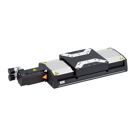
PI MS235E User manual

Physik Instrumente (PI) GmbH & Co. KG, Auf der Roemerstrasse 1, 76228 Karlsruhe, Germany
Phone +49 721 4846-0, Fax +49 721 4846-1019, Email info@pi.ws, www.pi.ws
MS235E
H
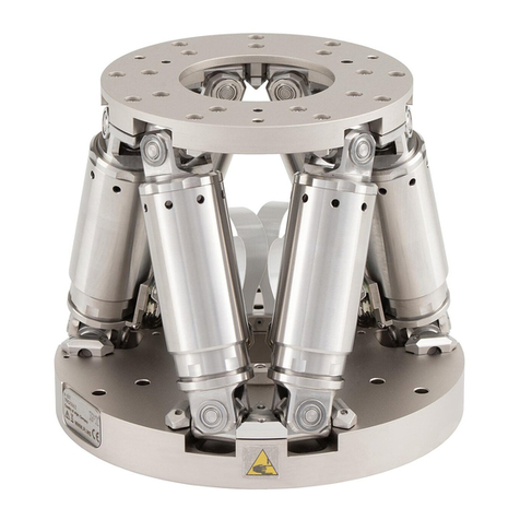
-811 Hexapod Microrobot
User Manual
Version: 2.4.0
Date: 24.08.2021
This document describes t
he following products:
H-811.I2
Miniature hexapod microrobot, brushless DC
motor, 5 kg load capacity, 10 mm/s max.
velocity, 0.5 m cable length. Connecting cables
are not in the scope of delivery and must be
ordered separately.
H-811.I2V
Miniature hexapod microrobot, brushless DC
motor, vacuum compatible to 10-6 hPa, 5 kg
load capacity, 10 mm/s velocity, cable set 2 m
vacuum side, feedthroughs. Air side connecting
cables are not included in the scope of delivery
and must be ordered separately.
H-811.F2
Miniature hexapod microrobot for optical
alignment, removable magnetic plate,
brushless DC motor, 5 kg load capacity, 10
mm/s max. velocity, 0.5 m cable length.
Connecting cables are not in the scope of
delivery and must be ordered separately.
H-811.S2
Miniature hexapod microrobot for high
dynamics applications, direct drive, 10 mm/s
maximum velocity, 1.5 kg load, 0.5 m cable
length. Connecting cables are not included in
the scope of delivery and must be ordered
separately.

The following company names and brands are registered trademarks ofPhysik Instrumente (PI) GmbH & Co.
KG:
PI®, NanoCube®, PICMA®, PILine®, NEXLINE®, PiezoWalk®, NEXACT®, Picoactuator®, PInano®, PIMag®,
Q-Motion®
The patents held by PI are found in our patent list: https://www.physikinstrumente.com/en/about-pi/patents
Notes on brand names and third-party trademarks:
BiSS isa registered trademark of iC-Haus GmbH.
©2021 Physik Instrumente (PI) GmbH & Co. KG, Karlsruhe, Germany. The text, photographs, and drawings in
this manual are protected by copyright. With regard thereto, Physik Instrumente (PI) GmbH & Co. KGretains
all the rights. The useofany text, images and drawings is permitted only in part and only when indicating the
source.
Original instructions
First printing: 24.08.2021
Document number: MS235E,Ewei, BRo, Version 2.4.0
Subject tochange. This manual is superseded byany new release. The latest respective release is available for
download (p. 3) on our website.

1About this Document 1
1.1 Objective and Target Audience of this User Manual.................................................. 1
1.2 Symbols and Typographic Conventions...................................................................... 1
1.3 Figures ........................................................................................................................ 2
1.4 Other Applicable Documents ..................................................................................... 2
1.5 Downloading Manuals................................................................................................ 3
2Safety 5
2.1 Intended Use .............................................................................................................. 5
2.2 General Safety Instructions ........................................................................................ 5
2.3 Organizational Measures............................................................................................ 5
2.4 Measures for Handling Vacuum-Compatible Products.............................................. 6
3Product Description 7
3.1 Features and Applications .......................................................................................... 7
3.2 Model Overview ......................................................................................................... 7
3.3 Suitable Controllers .................................................................................................... 8
3.4 Product View .............................................................................................................. 9
3.5 Scope of Delivery........................................................................................................ 9
3.6 Accessories ............................................................................................................... 12
3.7 Technical Features.................................................................................................... 12
3.7.1 Struts............................................................................................................ 12
3.7.2 Reference Switch and Limit Switches.......................................................... 12
3.7.3 Control......................................................................................................... 13
3.7.4 Motion ......................................................................................................... 13
3.7.5 ID Chip.......................................................................................................... 18
4Unpacking 19
5Installation 23
5.1 General Notes on Installing ...................................................................................... 23
5.2 Determining the Permissible Load and Workspace ................................................. 24
5.3 Grounding the Hexapod ........................................................................................... 25
5.4 Fixing the data transmission cable with the connector holder................................ 26
5.5 Mounting the Hexapod on a Surface ....................................................................... 27
5.6 Fixing the Load to the Hexapod................................................................................ 28
5.7 Connecting the Hexapod to the Controller .............................................................. 31
Contents
6Startup 37
6.1 General Notes on Startup......................................................................................... 37
6.2 Starting Up the Hexapod System ............................................................................. 38
6.3 Optional: Operating the Hexapod with a Separate 12 V Power Adapter ................ 39
7Maintenance 43
7.1 Performing a Maintenance Run ............................................................................... 43
7.2 Packing the Hexapod for Transport.......................................................................... 43
7.3 Cleaning the Hexapod .............................................................................................. 48
8Troubleshooting 49
9Customer Service 55
10 Technical Data 57
10.1 Specifications............................................................................................................ 57
10.1.1 Data Table.................................................................................................... 57
10.1.2 Specifications for Vacuum-Compatible Versions ........................................ 65
10.1.3 Maximum Ratings........................................................................................ 69
10.1.4 Specifications for Data Transmission and Power Supply Cables ................. 69
10.2 Ambient Conditions and Classifications ................................................................... 71
10.3 Dimensions ............................................................................................................... 72
10.3.1 H-811 Hexapod ............................................................................................ 72
10.3.2 000067899 Connector Holder ..................................................................... 75
10.4 Load Curves .............................................................................................................. 76
10.5 Dynamic Operational Area of the H-811.S2 ............................................................. 82
10.6 Pin Assignment ......................................................................................................... 84
10.6.1 Power Supply Connection............................................................................ 84
10.6.2 Data Transmission Connection.................................................................... 85
11 Old Equipment Disposal 87
12 Glossary 89
13 Appendix 93
13.1 Explanations of the Performance Test Sheet ........................................................... 93
13.2 EU Declaration of Conformity .................................................................................. 95

1 About this Document
H-811 Hexapod Microrobot MS235E Version: 2.4.0 1
In this Chapter
Objective and Target Audience of this User Manual..................................................................... 1
Symbols and Typographic Conventions ......................................................................................... 1
Figures............................................................................................................................................ 2
Other Applicable Documents......................................................................................................... 2
Downloading Manuals ................................................................................................................... 3
1.1 Objective and Target Audience of this User Manual
This manual contains information on using the H-811 as intended.
It assumes that the reader has a fundamental understanding of basic servo systems as well as
motion control concepts and applicable safety procedures.
The latest versions of the user manuals are available for download (p. 3) on our website.
1.2 Symbols and Typographic Conventions
The following symbols and typographic conventions are used in this user manual:
CAUTION
Dangerous situation
Failure to comply could lead to minor injury.
Precautionary measures for avoiding the risk.
NOTICE
Dangerous situation
Failure to comply could cause damage to equipment.
Precautionary measures for avoiding the risk.
1
About this Document

1 About this Document
2 Version: 2.4.0 MS235E H-811 Hexapod Microrobot
INFORMATION
Information for easier handling, tricks, tips, etc.
Symbol/
Label
Meaning
1.
2.
Action consisting of several steps whose sequential
order must be observed
Action consisting of one or several steps whose
sequential order is irrelevant
List item
p. 5 Cross-reference to page 5
RS-232
Labeling of an operating element on the product
(example: socket of the RS-232 interface)
Warning sign on the product which refers to detailed
information in this manual.
1.3 Figures
For better understandability, the colors, proportions, and degree of detail in illustrations can
deviate from the actual circumstances. Photographic illustrations may also differ and must not
be seen as guaranteed properties.
1.4 Other Applicable Documents
The devices and software tools from PI mentioned in this documentation are described in
separate manuals.
Device/program Document
no.
Document content
C-887.5xx controller
MS247EK
Short instructions for hexapod systems
MS244E
User manual
C887T0011
EtherCAT interface of the C-887.53 controller series
C887T0007
Coordinate Systems for Hexapod Microrobots
C887T0021
Motion of the Hexapod. Position and Orientation in Space,
Center of Rotation

1 About this Document
H-811 Hexapod Microrobot MS235E Version: 2.4.0 3
PI Hexapod Simulation
Tool
A000T0068
Determining the workspace and the permissible load of the
hexapod
PC software included in
the controller's scope of
delivery
Various
For details, see the user manual for the C-887.5xx
controller.
1.5 Downloading Manuals
INFORMATION
If a manual is missing or problems occur with downloading:
Contact our customer service department (p. 55).
Downloading Manuals
1. Open the website www.pi.ws.
2. Search the website for the product number (e.g., P-882) or the product family (e.g.,
PICMA® bender).
3. Click the corresponding product to open the product detail page.
4. Click the Downloads tab.
The manuals are shown under Documentation. Software manuals are shown under
General Software Documentation.
5. Click the desired manual and fill out the inquiry form.
The download link will then be sent to the email address entered.


2 Safety
H-811 Hexapod Microrobot MS235E Version: 2.4.0 5
In this Chapter
Intended Use.................................................................................................................................. 5
General Safety Instructions............................................................................................................ 5
Organizational Measures............................................................................................................... 5
Measures for Handling Vacuum-Compatible Products ................................................................. 6
2.1 Intended Use
The hexapod microrobot (short "hexapod") is a laboratory device as defined by DIN EN 61010-1.
It is built for indoor use and use in an environment which is free of dirt, oil, and lubricants.
In accordance with its design, the hexapod is intended for positioning, adjusting, and shifting of
loads on six axes at various velocities.
The hexapod can only be used as intended in conjunction with a suitable controller available
from PI (p. 8), which coordinates all motion of the hexapod.
2.2 General Safety Instructions
The H-811 is built according to state-of-the-art technology and recognized safety standards.
Improper use can result in personal injury and/or damage to the H-811.
Use the H-811 for its intended purpose only, and only when it is in perfect technical
condition.
Read the user manual.
Eliminate any malfunctions that may affect safety immediately.
The operator is responsible for the correct installation and operation of the H-811.
2.3 Organizational Measures
User manual
Always keep this user manual together with the H-811.
The latest versions of the user manuals are available for download (p. 3) on our
website.
2
Safety

2 Safety
6 Version: 2.4.0 MS235E H-811 Hexapod Microrobot
Add all information from the manufacturer to the user manual, for example
supplements or technical notes.
If you give the H-811 to a third party, include this user manual as well as other relevant
information provided by the manufacturer.
Do the work only if the user manual is complete. Missing information due to an
incomplete user manual can result in minor injury and damage to equipment.
Install and operate the H-811 only after you have read and understood this user
manual.
Personnel qualification
The H-811 may only be installed, started, operated, maintained, and cleaned by authorized and
appropriately qualified personnel.
2.4 Measures for Handling Vacuum-Compatible Products
When handling the vacuum version of the hexapod, attention must be paid to appropriate
cleanliness. At PI, all parts are cleaned before assembly. During assembly and measurement,
powder-free gloves are worn. Afterwards, the hexapod is cleaned once again by wiping and
shrink-wrapped twice in vacuum-compatible film.
Touch the hexapod only with powder-free gloves.
If necessary, wipe the hexapod clean after unpacking.

3 Product Description
H-811 Hexapod Microrobot MS235E Version: 2.4.0 7
In this Chapter
Features and Applications ............................................................................................................. 7
Model Overview............................................................................................................................. 7
Suitable Controllers ....................................................................................................................... 8
Product View.................................................................................................................................. 9
Scope of Delivery ........................................................................................................................... 9
Accessories................................................................................................................................... 12
Technical Features ....................................................................................................................... 12
3.1 Features and Applications
The various models (p. 7) of H-811 hexapod that are offered differ with respect to the
maximum velocity, and load capacity as well as suitability for use in a vacuum.
The parallel-kinematic design offers the following advantages:
Positioning operations in six independent axes (three translational axes, three
rotational axes) with short settling times
The center of rotation moves together with the motion platform
High accuracy and step resolution in all axes
No accumulation of errors of individual axes
No friction and torques from moving cables
The hexapod is controlled with a controller that can be ordered separately from PI (p. 8). The
position commands to the controller are entered as Cartesian coordinates.
3.2 Model Overview
Model Designation
H-811.I2
Miniature Hexapod microrobot, brushless DC motor, 5 kg load
capacity, 10 mm/s max. velocity, 0.5 m cable length. Connecting
cables are not in the scope of delivery and must be ordered
separately.
H-811.I2V
Miniature Hexapod microrobot, brushless DC motor, vacuum
compatible to 10-6 hPa, 5 kg load capacity, 10 mm/s velocity, cable set
2 m vacuum side, feedthroughs. Air side connecting cables are not
included in the scope of delivery and must be ordered separately.
3
Product Description

3 Product Description
8 Version: 2.4.0 MS235E H-811 Hexapod Microrobot
H-811.F2
Miniature-Hexapod microrobot for optical alignment, removable
magnetic plate, brushless
DC motor, 5 kg load capacity, 10 mm/s max.
velocity, 0.5 m cable length. Connecting cables are not in the scope of
delivery and must be ordered separately.
H-811.S2
Miniature hexapod microrobot for high dynamics applications, direct
drive, 10 mm/s maximum velocity, 1.5 kg load, 0.5 m cable length.
Connecting cables are not included in the scope of delivery and must
be ordered separately.
3.3 Suitable Controllers
Model Description
C-887.52
6-axis controller for hexapods, TCP/IP, RS-232, benchtop device, incl.
control of two additional axes
C-887.521
6-axis controller for hexapods, TCP/IP, RS-232, benchtop device, incl.
control of two additional axes, analog inputs
C-887.522
6-axis controller for hexapods, TCP/IP, RS-232, benchtop device, incl.
control of two additional axes, motion stop
C-887.523
6-axis controller for hexapods, TCP/IP, RS-232, benchtop device, incl.
control of two additional axes, motion stop, analog inputs
C-887.53
6-axis controller for hexapods, TCP/IP, RS-232, benchtop device, incl.
control of two additional axes, EtherCAT interface
C-887.531
6-axis controller for hexapods, TCP/IP, RS-232, benchtop device, incl.
control of two additional axes, EtherCAT interface, analog inputs
C-887.532 6-axis controller for hexapods, TCP/IP, RS-232, benchtop device, incl.
control of two additional axes, EtherCAT interface, motion stop
C-887.533
6-axis controller for hexapods, TCP/IP, RS-232, benchtop device, incl.
control of two additional axes, EtherCAT interface, motion stop, analog
inputs
To order, contact our customer service department (p. 55).

3 Product Description
H-811 Hexapod Microrobot MS235E Version: 2.4.0 9
3.4 Product View
Figure 1: Product view, H-811.F2 left, H-811.I2 right (applies to H-811.I2V and H-811.S2 also)
1Motion platform
2Strut
3Data transmission cable
4Power supply cable
5Base plate
6Mounting plate, held by magnets
3.5 Scope of Delivery
Order number Components
H-811
Hexapod according to your order (p. 7).
H-811.I2, F2, .S2: Cables with a length of 0.5 m are
installed permanently.
H-811.I2V: Cables with a length of 2 m are installed
permanently.
Note that the cables required for connecting the H-811 to the
electronics must be ordered separately.

3 Product Description
10 Version: 2.4.0 MS235E H-811 Hexapod Microrobot
H-811.I2V vacuum-compatible model only:
4668
Vacuum feedthrough for data transmission, HD D-sub
78 m/f
C887B0002
Vacuum feedthrough for power supply, LEMO 2-pole (f)
to M12 (m)
H-811.I2, .F2, .S2 models only:
000067899
Connector holder for fixing the data transmission cable
Packaging, consisting of:
Outer box
Inner box
Eight cushioned corners for inner box
Foam insert for inner box, with separate clamp
Pallet
Documentation, consisting of:
H811T0001
Technical note on unpacking the hexapod
MS247EK
Short instructions for hexapod systems
E712T0016
H-811.F2 model only:
Fast, multichannel alignment in photonics
Screw sets:
000020110
Mounting kit:
6 socket head screws, M4×25 ISO 4762
1 hex key 3.0 DIN 911
000036450
Accessories for connecting to the grounding system:
1 flat-head screw with cross recess, M4x8 ISO 7045
2 flat washers, form A-4.3 DIN 7090
2 lock washers, Schnorr Ø 4 mm N0110

3 Product Description
H-811 Hexapod Microrobot MS235E Version: 2.4.0 11
000070600
H-811.I2, .F2, .S2 models only:
Accessory for fixing the connector holder to the data
transmission cable:
2 socket head screws, M6×30 ISO 4762
1 hex key 5.0 DIN 911
Note that the cables required for connecting the H-811 to the electronics must be ordered
separately:
Order Number Data Transmission Cables, Available Lengths
C-815.82D02
Data transmission cable for hexapods, drag-chain compatible, HD D-sub 78
m/f, 2 m
C-815.82D03
Data transmission cable for hexapods, drag-chain compatible, HD D-sub 78
m/f, 3 m
C-815.82D05
Data transmission cable for hexapods, drag-chain compatible, HD D-sub 78
m/f, 5 m
C-815.82D07 Data transmission cable for hexapods, drag-chain compatible, HD D-sub 78
m/f, 7.5 m
C-815.82D10
Data transmission cable for hexapods, drag-chain compatible, HD D-sub 78
m/f, 10 m
C-815.82D20
Data transmission cable for hexapods, drag-chain compatible, HD D-sub 78
m/f, 20 m
Order Number Power Supply Cables, Available Lengths
C-815.82P02E
Power supply cable for hexapods, drag-chain compatible, M12 m/f straight,
2 m
C-815.82P03E
Power supply cable for hexapods, drag-chain compatible, M12 m/f straight,
3 m
C-815.82P05E
Power supply cable for hexapods, drag-chain compatible, M12 m/f straight,
5 m
C-815.82P07E
Power supply cable for hexapods, drag-chain compatible, M12 m/f straight,
7.5 m
C-815.82P10E
Power supply cable for hexapods, drag-chain compatible, M12 m/f straight,
10 m
C-815.82P20E
Power supply cable for hexapods, drag-chain compatible, M12 m/f straight,
20 m
To order, contact our customer service department (p. 55).

3 Product Description
12 Version: 2.4.0 MS235E H-811 Hexapod Microrobot
3.6 Accessories
Order number Description
H-811.12PS
Separate 12 V wide input range power supply (60 W/5 A) for use with line
voltages from 100 to 240 V AC and voltage frequencies of 50 or 60 Hz, with
4-pin M12 connector (f)
Optional power supply for the hexapod. Replaces the power supply from
the controller. Ideal for static applications that require increased position
stability.
For further information, see "Optional: Operating the Hexapod with a
Separate 12 V Power Adapter" (p. 39).
F-206.TMU
H-811.F2 model only: Mounting plate for fast replacement of different
assemblies
R-FMP-GSM
Fast, multi-channel gradient search routines
Available for hexapod mechanics H-811.F2 and H-811.I2 in combination
with a C-887 hexapod controller that features a high-resolution analog
input. Installation is done by a PI service engineer in a remote session.
Contact will be established by PI after purchase.
3.7 Technical Features
3.7.1 Struts
The hexapod has six adjustable-length struts. Each strut carries out linear motion. Each set of
settings of the six struts defines a position of the motion platform in six degrees of freedom
(three translational axes and three rotational axes).
Each strut is equipped with the following components:
One actuator
Reference and limit switches
Joints for connecting to the base plate and motion platform
The actuator contains a brushless DC motor with an incremental rotary encoder and a drive
screw.
3.7.2 Reference Switch and Limit Switches
The reference switch of a strut functions independently of the angular positions of the strut
ends and the lengths of the other struts.
When a limit switch is activated, the power source of the motor is switched off to protect the
hexapod against damage from malfunctions.

3 Product Description
H-811 Hexapod Microrobot MS235E Version: 2.4.0 13
3.7.3 Control
Der hexapod is intended for operation with a suitable controller from PI (p. 8). The controller
makes it possible to command motion of individual axes, combinations of axes or all six axes at
the same time in a single motion command.
The controller calculates the settings for the individual struts from the target positions given for
the translational and rotational axes. The velocities and accelerations of the struts are
calculated so that all struts start and stop at the same time.
Every time the controller of a hexapod equipped with incremental encoders is switched on or
rebooted, the hexapod must complete a reference move, in which each strut moves to its
reference switch. After the reference move, the motion platform is in the reference position
and can be commanded to move to absolute target positions.
For further information, see the user manual for the controller.
3.7.4 Motion
The platform moves along the translational axes X, Y, and Z and around the rotational axes U, V,
and W.
Using the controller, custom coordinate systems can be defined and used instead of the default
coordinate system.
Default and user-defined coordinate systems are always right-handed systems. It is not possible
to convert a right-handed system to a left-handed system.

3 Product Description
14 Version: 2.4.0 MS235E H-811 Hexapod Microrobot
The following is a description of how the hexapod behaves with the default coordinate system.
Work with user-defined coordinate systems is described in the C887T0007 technical note.
Figure 2: Coordinate system and rotations to the rotational coordinates U, V, and W. The coordinate
system is depicted above the platform for better clarity.
Translation
Translations are described in the spatially-fixed coordinate system. The translational axes X, Y,
and Z meet at the origin of the coordinate system (0,0,0). For further information, see the
glossary (p. 89).

3 Product Description
H-811 Hexapod Microrobot MS235E Version: 2.4.0 15
Rotation
Rotations take place around the rotational axes U, V, and W. The rotational axes meet at the
center of rotation (also referred to as "pivot point"). The rotational axes and therefore also the
center of rotation always move together with the platform of the hexapod (see also the
example below for consecutive rotations).
A given rotation in space is calculated from the individual rotations in the order U -> V- > W.
For further information on the center of rotation, see the glossary (p. 89).
INFORMATION
The dimensional drawing (p. 72) contains the following:
Orientation of the default coordinate system
Position of the default center of rotation
Example: Consecutive rotations
INFORMATION
For a clearer view, the figures have been adapted as follows:
Round platform replaced by T-shaped platform
Coordinate system shown shifted
Center of rotation in the top left corner of the platform
1. The U axis is commanded to move to position 10.
The rotation around the U axis tilts the rotational axes V and W.

3 Product Description
16 Version: 2.4.0 MS235E H-811 Hexapod Microrobot
Figure 3: Rotation around the U axis
Platform in reference position
Platform position: U = 10 (U parallel to spatially-fixed X axis)
1. The V axis is commanded to move to position –10.
The rotation takes place around rotational axis V, which was tilted during the previous
rotation.
The rotation around the V axis tilts the rotational axes U and W.
This manual suits for next models
1
Table of contents
Other PI Industrial Equipment manuals
Popular Industrial Equipment manuals by other brands

Siemens
Siemens SIVACON 8PS LX Series installation instructions

SMC Networks
SMC Networks EX510 Series manual

Festo
Festo HGP A-B Series operating instructions

Master
Master C150 Service and repair manual

SEW-Eurodrive
SEW-Eurodrive MOVIGEAR MGF-DBC Series operating instructions

Siemens
Siemens 3VW9727-0AB11 operating instructions