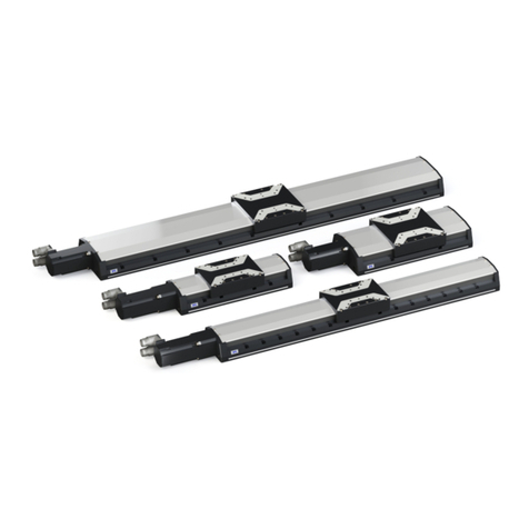
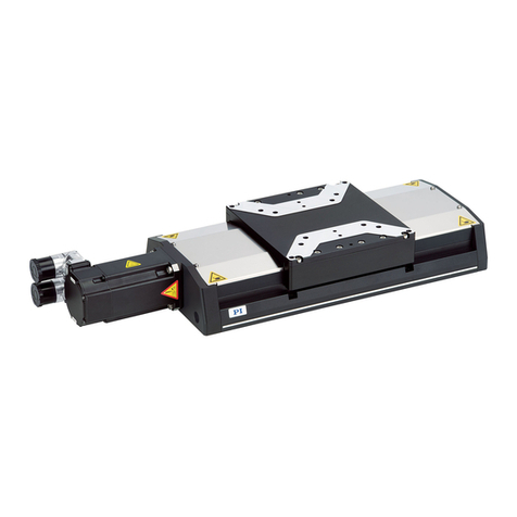
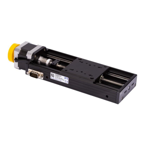
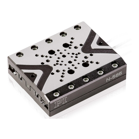
PI NEXACT Stage N-565 Series User manual

Physik Instrumente (PI) GmbH & Co. KG, Auf der Roemerstrasse 1, 76228 Karlsruhe, Germany
Phone +49 721 4846-0, Fax +49 721 4846-1019, Email [email protected], www.pi.ws
MP148E
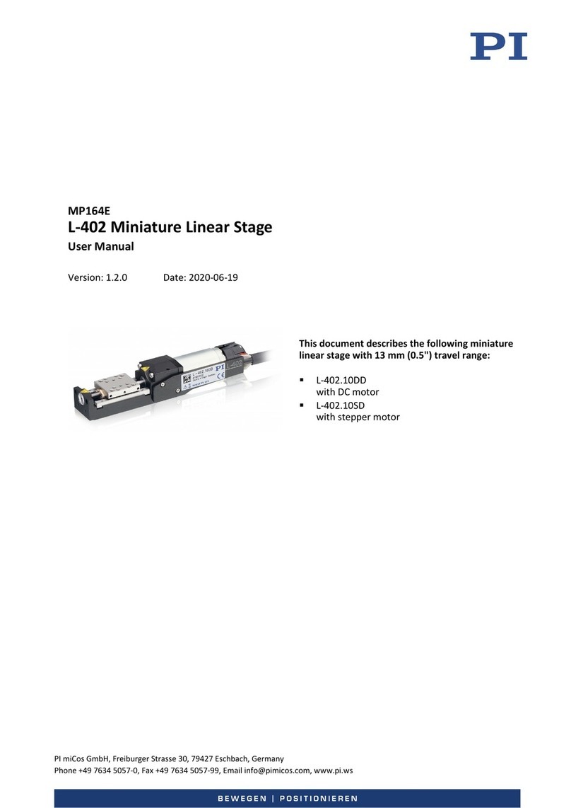
N-565 NEXACT® Linear Stage
User Manual
Version: 1.4.0
Date: 10.06.2020
This document describes the following products:
N-565.160
Precision linear stage, 13 mm travel range,
PIOne linear encoder, 0.5 nm resolution, 10 N
drive force, dimensions 65 × 80 × 20 mm (W × L
× H), NEXACT® piezoelectric walking drive
N-565.260
Precision linear stage, 26 mm travel range,
PIOne linear encoder, 0.5 nm resolution, 10 N
drive force, dimensions 65
× 110 × 20 mm (W ×
L × H), NEXACT® piezoelectric walking drive
N-565.360
Precision linear stage, 52 mm travel range,
PIOne linear encoder, 0.5 nm resolution, 10 N
drive force, dimensions 65 × 160 × 20 mm (W ×
L × H), NEXACT® piezoelectric walking drive

Physik Instrumente (PI) GmbH & Co. KG is the owner of the following trademarks:
PI®, PIC®, PICMA®, PILine®, PIFOC, PIMag®, PiezoWalk®, NEXACT®, NEXLINE®, NanoCube®, NanoAutomation®
© 2020 Physik Instrumente (PI) GmbH & Co. KG, Karlsruhe, Germany. The text, photographs and drawings in
this manual are protected by copyright. With regard thereto, Physik Instrumente (PI) GmbH & Co. KG retains
all the rights. The use of any text, images and drawings is permitted only in part and only when indicating the
source.
Original instructions
First printing: 10.06.2020
Document number: MP148E, LMo / CBo, Version 1.4.0
Subject to change without notice. This manual is superseded by any new release. The latest release is
available for download (p. 3) on our website.

1About this Document 1
1.1 Objective and Target Audience of this User Manual ................................................. 1
1.2 Symbols and Typographic Conventions ..................................................................... 1
1.3 Definition of Terms..................................................................................................... 2
1.4 Figures ........................................................................................................................ 2
1.5 Other Applicable Documents ..................................................................................... 2
1.6 Downloading Manuals................................................................................................ 3
2Safety 5
2.1 Intended Use .............................................................................................................. 5
2.2 General Safety Instructions ........................................................................................ 5
2.3 Organizational Measures............................................................................................ 6
3Product Description 7
3.1 Model Overview ......................................................................................................... 7
3.2 Product View .............................................................................................................. 8
3.2.1 Product Details .............................................................................................. 8
3.2.2 Product Labeling............................................................................................ 8
3.3 Scope of Delivery........................................................................................................ 9
3.4 Suitable Controllers .................................................................................................... 9
3.5 Technical Features.................................................................................................... 10
3.5.1 Linear Encoder (Sensor)............................................................................... 10
3.5.2 Reference Switch ......................................................................................... 10
4Unpacking 11
5Installation 13
5.1 General Notes on Installation................................................................................... 13
5.2 Mounting the N-565 onto a Surface......................................................................... 15
5.3 Building an XY System .............................................................................................. 18
5.4 Fixing the Load to the N-565 .................................................................................... 20
5.5 Connecting the N-565 to the Controller................................................................... 22
6Startup and Operation 23
6.1 General Notes on Startup and Operation ................................................................ 23
6.2 Operating Parameters .............................................................................................. 24
6.3 Operating the N-565................................................................................................. 25
Contents
6.4 Discharging the Piezo Actuators of the Drive........................................................... 25
7Maintenance 27
7.1 General Notes on Maintenance ............................................................................... 27
7.2 Cleaning the N-565................................................................................................... 27
8Troubleshooting 29
8.1 General Notes on Troubleshooting .......................................................................... 29
8.2 Possible Causes and Correction................................................................................ 30
9Customer Service 31
10 Technical Data 33
10.1 Specifications............................................................................................................ 33
10.1.1 Data Table.................................................................................................... 33
10.1.2 Ambient Conditions and Classifications ...................................................... 34
10.2 Maximum Ratings..................................................................................................... 35
10.3 Dimensions ............................................................................................................... 36
10.4 Pin Assignment ......................................................................................................... 37
10.4.1 Drive Connector........................................................................................... 37
10.4.2 Sensor Connector ........................................................................................ 38
10.4.3 Pin Assignment of the N664B0001 Adapter................................................ 39
11 Old Equipment Disposal 41
12 EU Declaration of Conformity 43

1 About this Document
N-565 NEXACT® Linear Stage MP148E Version: 1.4.0 1
In this Chapter
Objective and Target Audience of this User Manual ..................................................................... 1
Symbols and Typographic Conventions......................................................................................... 1
Definition of Terms ........................................................................................................................ 2
Figures............................................................................................................................................ 2
Other Applicable Documents......................................................................................................... 2
Downloading Manuals ................................................................................................................... 3
1.1 Objective and Target Audience of this User Manual
This manual contains information on using the N-565 as intended.
It assumes that the reader has a fundamental understanding of basic servo systems as well as
motion control concepts and applicable safety procedures.
The latest versions of the user manuals are available for download (p. 3) on our website.
1.2 Symbols and Typographic Conventions
The following symbols and typographic conventions are used in this user manual:
CAUTION
Dangerous situation
Failure to comply could lead to minor injury.
Precautionary measures for avoiding the risk.
NOTICE
Dangerous situation
Failure to comply could cause damage to equipment.
Precautionary measures for avoiding the risk.
INFORMATION
Information for easier handling, tricks, tips, etc.
1
About this Document

1 About this Document
2 Version: 1.4.0 MP148E N-565 NEXACT® Linear Stage
Symbol/
Label
Meaning
1.
2.
Action consisting of several steps with strict sequential order
Action consisting of one or more steps without relevant sequential
order
Lists
p. 5
Cross-reference to page 5
RS-232
Label on the product indicating an operating element (example:
RS-232 interface socket)
Warning signs on the product referring to detailed information in this
manual
1.3 Definition of Terms
Term Explanation
Load capacity
Maximum load capacity in the vertical direction when the positioner
is mounted horizontally. The contact point of the load is in the center
of the motion platform.
Linear encoder
The linear encoder is an incremental sensor for detecting changes in
position. Signals from the sensor are used for axis position feedback.
After switching the controller on, referencing must be done before
absolute target positions can be commanded and reached.
1.4 Figures
For better understandability, the colors, proportions, and degree of detail in illustrations can
deviate from the actual circumstances. Photographic illustrations may also differ and must not
be seen as guaranteed properties.
1.5 Other Applicable Documents
The devices and software tools from PI mentioned in this documentation are described in
separate manuals.
Product Document
E-861 NEXACT® Servo Controller
PZ205E User Manual
PIMikroMove SM148E Software Manual
PIUpdateFinder
A000T0028 User Manual

1 About this Document
N-565 NEXACT® Linear Stage MP148E Version: 1.4.0 3
1.6 Downloading Manuals
INFORMATION
If a manual is missing or problems occur with downloading:
Contact our customer service department (p. 31).
Downloading manuals
1. Open the website www.pi.ws.
2. Search the website for the product number (e.g., N-565) or the product family (e.g.,
NEXACT®).
3. Click the corresponding product to open the product detail page.
4. Click Downloads.
The manuals are shown under Documentation.
5. Click the desired manual and fill out the inquiry form.
The download link will then be sent to the email address entered.


2 Safety
N-565 NEXACT® Linear Stage MP148E Version: 1.4.0 5
In this Chapter
Intended Use.................................................................................................................................. 5
General Safety Instructions ........................................................................................................... 5
Organizational Measures ............................................................................................................... 6
2.1 Intended Use
The N-565 is a laboratory device as defined by DIN EN 61010-1. It is intended for indoor use and
use in an environment that is free of dirt, oil, and lubricants.
According to its design, the N-565 is intended for positioning, adjusting and shifting loads in one
axis at various velocities.
The N-565 is a positioner for nanopositioning technology. The feed is generated by NEXACT®
piezo actuators coupled to a ceramic rail (PiezoWalk® principle).
The N-565 is equipped with a linear encoder for direct position measuring.
It is only possible to use the N-565 as intended when it is installed and only in conjunction with
a suitable controller (p. 9). The controller is not included in the scope of delivery of the N-565.
2.2 General Safety Instructions
The N-565 is built according to state-of-the-art technology and recognized safety standards.
Improper use can result in personal injury and/or damage to the N-565.
Use the N-565 for its intended purpose only, and only when it is in perfect technical
condition.
Read the user manual.
Eliminate any malfunctions that may affect safety immediately.
The operator is responsible for the correct installation and operation of the N-565.
2
Safety

2 Safety
6 Version: 1.4.0 MP148E N-565 NEXACT® Linear Stage
2.3 Organizational Measures
User manual
Always keep this user manual together with the N-565.
The latest versions of the user manuals are available for download (p. 3) on our
website.
Add all information from the manufacturer to the user manual, for example
supplements or technical notes.
If you give the N-565 to a third party, include this user manual as well as other relevant
information provided by the manufacturer.
Do the work only if the user manual is complete. Missing information due to an
incomplete user manual can result in minor injury and damage to equipment.
Install and operate the N-565 only after you have read and understood this user
manual.
Personnel qualification
The N-565 may only be installed, started, operated, maintained, and cleaned by authorized and
appropriately qualified personnel.

3 Product Description
N-565 NEXACT® Linear Stage MP148E Version: 1.4.0 7
In this Chapter
Model Overview............................................................................................................................. 7
Product View.................................................................................................................................. 8
Scope of Delivery ........................................................................................................................... 9
Suitable Controllers ....................................................................................................................... 9
Technical Features ....................................................................................................................... 10
3.1 Model Overview
The N-565 is available in the following versions:
Model Description
N-565.160
Precision linear stage, 13 mm travel range, PIOne linear encoder, 0.5 nm
resolution, 10 N drive force, dimensions 65 × 80 × 20 mm (W × L × H),
NEXACT® piezoelectric walking drive
N-565.260
Precision linear stage, 26 mm travel range, PIOne linear encoder, 0.5 nm
resolution, 10 N drive force, dimensions 65 × 110 × 20 mm (W × L × H),
NEXACT® piezoelectric walking drive
N-565.360
Precision linear stage, 52 mm travel range, PIOne linear encoder, 0.5 nm
resolution, 10 N drive force, dimensions 65 × 160 × 20 mm (W × L × H),
NEXACT® piezoelectric walking drive
3
Product Description

3 Product Description
8 Version: 1.4.0 MP148E N-565 NEXACT® Linear Stage
3.2 Product View
3.2.1 Product Details
Figure 1: N-565 product view
1
Motion platform
2Cable exit (cable for sensor and drive connector)
3Base body
The arrow in the figure shows the positive direction of motion.
3.2.2 Product Labeling
Labeling Description
N-565 / N-565.x60
Product name. Characters following the period identify the
model exactly.
123456789
Serial number (example), individual for each N-565
Meaning of each position (from the left):
1 = internal information
2 and 3 = year of manufacture
4 to 9 = consecutive number
Warning sign "Pay attention to the manual!"
Old equipment disposal (p. 41)
Country of origin: Germany
Country of origin
Manufacturer's logo
www.pi.de
Manufacturer's address (website)
CE conformity mark

3 Product Description
N-565 NEXACT® Linear Stage MP148E Version: 1.4.0 9
Labeling Description
Symbol for the protective earth conductor, marks the position of
the holes via which the N-565 is to be connected to the
protective earth conductor
Notice of laser radiation (p. 29) (here: top of sensor socket)
Warning sign "Pay attention to the manual!" (here: top of sensor
socket)
Warning sign and values for the laser (p. 29) (here: bottom of
sensor socket)
3.3 Scope of Delivery
Product number Description
N-565
Positioner according to order (p. 7)
5860500028 Screw set for mounting of the N-565:
4 socket head screws, M3x12, ISO 4762
2 dowel pins, 3 m6 × 8, ISO 2338
N664B0001
Adapter D-sub 15 (m) to HD D-sub 15 (f) for sensor connector
MP137EK
Short instructions for NEXACT® positioners
3.4 Suitable Controllers
Product number Description
E-861.1A1
PiezoWalk® NEXACT® controller, 1 axis, benchtop device, linear encoder,
USB and RS-232 interfaces, I/O, connector for joystick
To order, contact our customer service department (p. 31).

3 Product Description
10 Version: 1.4.0 MP148E N-565 NEXACT® Linear Stage
3.5 Technical Features
3.5.1 Linear Encoder (Sensor)
The positioner is equipped with an optical linear encoder. Refer to the table in the
"Specifications" section (p. 33) for the encoder resolution.
Optical linear encoders measure the actual position directly (direct metrology). Therefore,
errors occurring in the drivetrain such as nonlinearity, backlash or elastic deformation, cannot
influence the measurement of the position.
3.5.2 Reference Switch
The positioner is equipped with a direction-sensing reference switch, which is located at about
the midpoint of the travel range. This sensor sends a TTL signal indicating whether the
positioner is on the positive or negative side of the reference switch.
See the controller user manual and/or associated software manuals for the commands that
make use of the reference point signal.

4 Unpacking
N-565 NEXACT® Linear Stage MP148E Version: 1.4.0 11
1. Unpack the N-565 with care.
2. Compare the contents with the scope of delivery according to the contract and the
delivery note.
3. Inspect the contents for signs of damage. If any parts are damaged or missing, contact
our customer service department (p. 31) immediately.
4. Keep all packaging materials in case the product needs to be returned.
Remove the protective foil
The top and bottom surfaces of the N-565 are scratch-sensitive. For this reason, the N-565 is
equipped with a protective foil.
Remove the protective foil from the top and bottom surfaces of the N-565 before using
for the first time.
N-565's delivery status Remove the protective foil N-565 without protective foil
4
Unpacking


5 Installation
N-565 NEXACT® Linear Stage MP148E Version: 1.4.0 13
In this Chapter
General Notes on Installation ...................................................................................................... 13
Mounting the N-565 onto a Surface ............................................................................................ 15
Building an XY System.................................................................................................................. 18
Fixing the Load to the N-565........................................................................................................ 20
Connecting the N-565 to the Controller ...................................................................................... 22
5.1 General Notes on Installation
NOTICE
Damage from changes in position due to external forces!
Moving the platform of the positioner by external forces can damage the drive. Changes in
position caused by external forces acting on the positioner can also damage the load or the
surroundings.
Make sure that forces acting the platform in the direction of motion do not exceed the
active push/pull force of the drive (p. 33) particularly when the positioner is mounted
vertically.
Trigger all motion by sending motion commands to the controller. Do not move the
platform by hand.
Figure 2: Accessible when the platform is moved out: Encoder scale
1
Bottom of the N-565's platform
2Scale of the linear encoder, do not touch!
5
Installation

5 Installation
14 Version: 1.4.0 MP148E N-565 NEXACT® Linear Stage
Figure 3: Accessible when the platform is moved out: Ceramic rail of the NEXACT® drive
1
Bottom of the N-565's platform
2Do not touch the ceramic rail of the NEXACT® drive!
NOTICE
Damage from mechanical actions!
The encoder scale of the linear encoder is scratch-sensitive and could be damaged by
mechanical actions, e.g., by pointed objects.
Treat the encoder scale with extreme care.
The encoder scale is not accessible in the reference position of the platform (delivery
condition). If necessary before installing and removing:
Start the positioner (p. 23) and do a reference move to the reference switch (refer to the
user manual for the controller).
NOTICE
Malfunction due to contamination!
Any type of contamination, e.g., dust, oil, lubricant or condensation, will render the N-565
inoperable.
Keep the N-565 free of dirt and condensation.
Avoid touching the ceramic rail of the NEXACT® drive and the encoder scale.
The ceramic rail and the encoder scale are not accessible in the reference position of the
platform (delivery condition). If necessary before installing and removing:
Start the positioner (p. 23) and do a reference move to the reference switch (refer to the
user manual for the controller).

5 Installation
N-565 NEXACT® Linear Stage MP148E Version: 1.4.0 15
NOTICE
Damage due to improper mounting!
Improper mounting of the N-565 or incorrectly mounted parts can damage the N-565.
Only use the holes or threads intended for the purpose of fixing the N-565 and loads.
Install the N-565 so that the platform and all parts attached to it can move freely withi
n the
entire travel range.
NOTICE
Warping of the N-565 when mounted on uneven surfaces!
The N-565 could warp if mounted on an uneven surface. Warping reduces the accuracy.
Mount the N-565 onto an even surface. The recommended flatness of the surface is
≤10 µm.
For applications with large temperature changes:
Mount the N-565 only onto surfaces that have the same or similar thermal expansion
properties as the N-565.
NOTICE
Damage due to unsuitable cables!
Unsuitable cables can damage the N-565 and the electronics.
Use cables provided by PI only to connect the N-565 to the electronics.
INFORMATION
For optimum repeatability, all components must be connected firmly together.
5.2 Mounting the N-565 onto a Surface
Options for mounting the N-565 onto an underlying surface
INFORMATION
The mounting holes in the base body of the positioner are only accessible from above when
the platform is in the reference position (delivery state). If necessary:
Start the positioner (p. 23) and do a reference move to the reference switch (refer to the
user manual for the controller).

5 Installation
16 Version: 1.4.0 MP148E N-565 NEXACT® Linear Stage
The mounting holes of the N-565 are intended for the following mounting options:
Mounting option Mounting holes, see "Dimensions" for details (p. 36)
Mounting from above
with M3x12 screws
Figure 4: N-565, top view: M4 holes (with core hole diameter Ø 3.4 mm
and counterbore), for mounting from above with M3 screws
Mounting from above
with M3x12 screws
For example, this
mounting is used when
building an XY system
consisting of two N-565
positioners (p. 18).
Figure 5: N-565, top view: holes with Ø 3.4 mm and counterbore, for
mounting from above with M3 screws
Mounting from below
with M4 screws
Figure 6: N-565, bottom view: M4 holes for mounting from below with
M4 screws
Other manuals for NEXACT Stage N-565 Series
2
This manual suits for next models
3
Table of contents
Other PI Industrial Equipment manuals
Popular Industrial Equipment manuals by other brands

Rohm
Rohm SuperLock HSK Series operating instructions

Thermo Scientific
Thermo Scientific CTS Xenon installation guide

Water Maze
Water Maze ALPHA-1500 Operator's manual

Buhler
Buhler GAS 222.10 Assembly, installation and operation instructions

Siemens
Siemens SIRIUS 3RT292 5A Series operating instructions

ABB
ABB TPS57-F33 Operation manual