Planet ICA-120 User manual

CMOS Box Internet Camera
ICA-120
User’s Manual
Version: 2.00
Date: April. 2009
1

Copyright
Copyright ©2009 by PLANET Technology Corp. All rights reserved. No part of this publication
may be reproduced, transmitted, transcribed, stored in a retrieval system, or translated into any
language or computer language, in any form or by any means, electronic, mechanical, magnetic,
optical, chemical, manual or otherwise, without the prior written permission of PLANET.
PLANET makes no representations or warranties, either expressed or implied, with respect to
the contents hereof and specifically disclaims any warranties, merchantability or fitness for any
particular purpose. Any software described in this manual is sold or licensed "as is". Should the
programs prove defective following their purchase, the buyer (and not PLANET, its distributor, or
its dealer) assumes the entire cost of all necessary servicing, repair, and any incidental or
consequential damages resulting from any defect in the software. Further, PLANET reserves the
right to revise this publication and to make changes from time to time in the contents hereof
without obligation to notify any person of such revision or changes.
All brand and product names mentioned in this manual are trademarks and/or
registered trademarks of their respective holders.
Federal Communication Commission Interference Statement
This equipment has been tested and found to comply with the limits for a Class B digital device,
pursuant to Part 15 of FCC Rules. These limits are designed to provide reasonable protection
against harmful interference in a residential installation. This equipment generates, uses, and
can radiate radio frequency energy and, if not installed and used in accordance with the
instructions, may cause harmful interference to radio communications. However, there is no
guarantee that interference will not occur in a particular installation. If this equipment does cause
harmful interference to radio or television reception, which can be determined by turning the
equipment off and on, the user is encouraged to try to correct the interference by one or more of
the following measures:
1. Reorient or relocate the receiving antenna.
2. Increase the separation between the equipment and receiver.
3. Connect the equipment into an outlet on a circuit different from that to which the receiver
is connected.
4. Consult the dealer or an experienced radio technician for help.
FCC Caution
To assure continued compliance. (example-use only shielded interface cables when connecting
to computer or peripheral devices). Any changes or modifications not expressly approved by the
party responsible for compliance could void the user’s authority to operate the equipment.
This device complies with Part 15 of the FCC Rules. Operation is subject to the Following two
conditions: ( 1 ) This device may not cause harmful interference, and ( 2 ) this Device must
accept any interference received, including interference that may cause undesired operation.
Federal Communication Commission (FCC) Radiation Exposure Statement
This equipment complies with FCC radiation exposure set forth for an uncontrolled
environment. In order to avoid the possibility of exceeding the FCC radio frequency exposure
limits, human proximity to the antenna shall not be less than 20 cm (8 inches) during normal
operation.
1

Safety
This equipment is designed with the utmost care for the safety of those who install and use it.
However, special attention must be paid to the dangers of electric shock and static electricity
when working with electrical equipment. All guidelines of this and of the computer
manufacture must therefore be allowed at all times to ensure the safe use of the equipment.
CE Mark Warning
This is a Class B product. In a domestic environment, this product may cause radio
interference, in which case the user may be required to take adequate measures.
WEEE Regulation
To avoid the potential effects on the environment and human health as a result of the
presence of hazardous substances in electrical and electronic equipment, end users
of electrical and electronic equipment should understand the meaning of the
crossed-out wheeled bin symbol. Do not dispose of WEEE as unsorted municipal
waste and have to collect such WEEE separately.
Revision
User’s Manual for PLANET CMOS Box Internet Camera
Model: ICA-120
Rev: 2.0 (April. 2009)
Part No. EM-ICA120v2
2

Table of Content
1. Introduction................................................................................................................ 5
1.1 Overview............................................................................................................. 5
1.2 Features.............................................................................................................. 5
1.3 Package Contents............................................................................................. 5
2. Basic Setup............................................................................................................... 6
2.1 System Requirements....................................................................................... 6
2.2 Physical Description.......................................................................................... 6
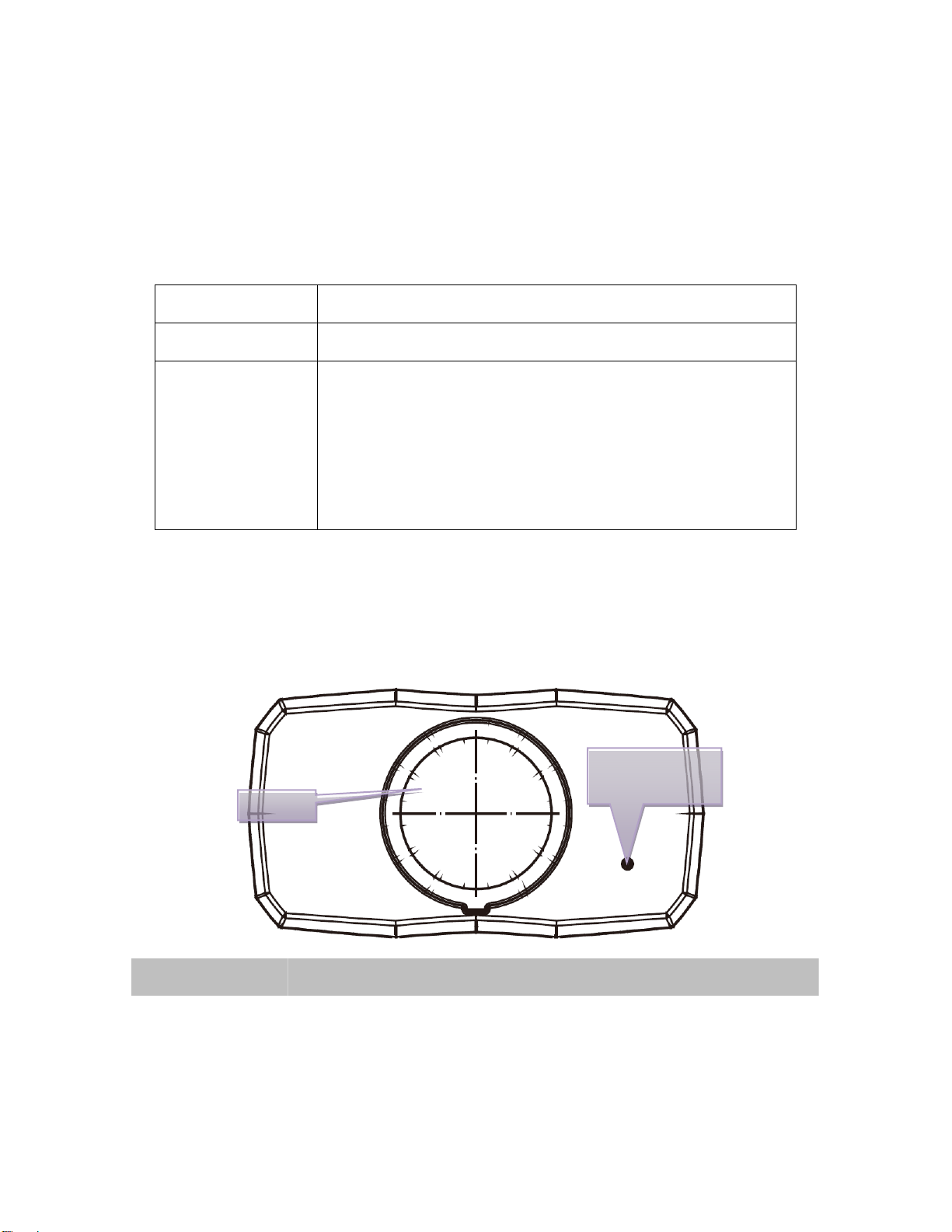
2.2.1 Front View ............................................................................................... 6
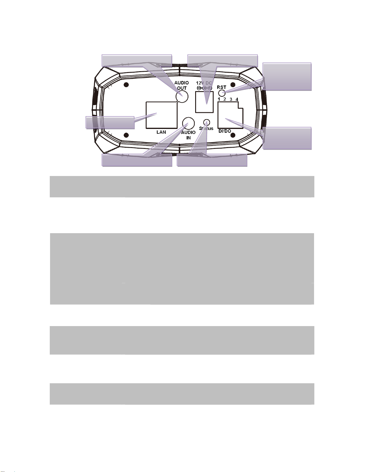
2.2.2 Rear View................................................................................................ 7
2.3 Hardware Installation........................................................................................ 8
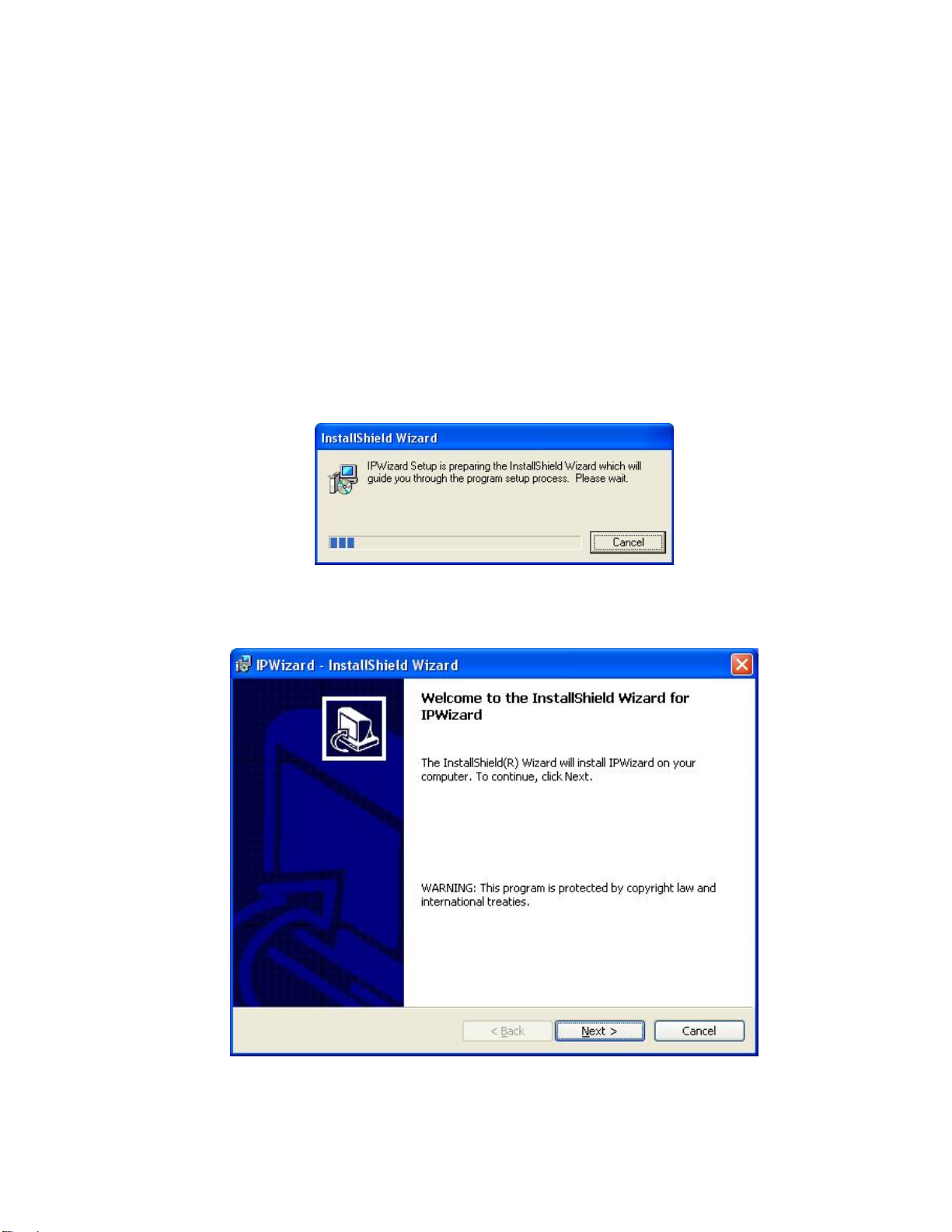
2.4 Initial Utility Installation ..................................................................................... 9
2.5 IP Wizard........................................................................................................... 12
2.6 Configure With IP Wizard............................................................................... 14
2.7 UPnP Function................................................................................................. 17
2.7.1 Windows XP.......................................................................................... 17
2.7.2 Windows Vista ...................................................................................... 21
2.8 Setup ActiveX to use the Camera................................................................. 23
2.8.1 Internet Explorer 6 for Windows XP.................................................. 23
2.8.2 Internet Explorer 7 for Windows XP.................................................. 24
2.8.3 Internet Explorer 7 for Windows Vista............................................... 25
3. Web-based Management...................................................................................... 26
3.1 Introduction....................................................................................................... 26
3.2 Connecting to Camera.................................................................................... 26
3.3 Live View........................................................................................................... 28
3.4 ActiveX Control ................................................................................................ 30
3.4.1 Digital Zoom.......................................................................................... 31
3.4.2 Record.................................................................................................... 31
3.4.3 Snapshot................................................................................................ 32
3.4.4 Voice....................................................................................................... 32
3.4.5 Statistics................................................................................................. 33
3.4.6 About...................................................................................................... 33
3.5 Network............................................................................................................. 34
3.5.1 Network.................................................................................................. 34
3.5.2 DDNS server......................................................................................... 35
3.5.3 PPPoE.................................................................................................... 37
3.5.4 Streaming .............................................................................................. 38
3.5.5 UPnP...................................................................................................... 40
3.5.6 IP Filter................................................................................................... 41
3.5.7 IP Notification........................................................................................ 42
3.6 Camera.............................................................................................................. 44
3.6.1 Picture.................................................................................................... 44
3.7 System............................................................................................................... 46
3.7.1 System................................................................................................... 46
3.7.2 Date & Time........................................................................................... 47
3.7.3 Maintenance.......................................................................................... 49
3

3.8 Video.................................................................................................................. 51
3.8.1 Common................................................................................................ 51
3.8.2 MPEG4/VGA......................................................................................... 52
3.8.3 MPEG4/QVGA...................................................................................... 53
3.8.4 MPEG4/QQVGA................................................................................... 54
3.8.5 VIDEO/JPEG......................................................................................... 55
3.9 Audio.................................................................................................................. 56
3.10 User................................................................................................................. 57
3.11 E-Mail............................................................................................................... 58
3.12 Object Detection............................................................................................ 59
3.13 Event Server .................................................................................................. 61
3.13.1 FTP Server.......................................................................................... 61
3.13.2 TCP Server.......................................................................................... 62
3.13.3 HTTP Server....................................................................................... 63
3.14 Event Schedule.............................................................................................. 64
3.14.1 Setting.................................................................................................. 64
3.14.2 Record ................................................................................................. 65
Appendix A: Reset Factory Default Settings.............................................................. 66
Appendix B: PING IPAddress...................................................................................... 67
Appendix C: Bandwidth and Video Size Estimation................................................. 68
Appendix D: DDNS Application.................................................................................... 70
Appendix E: Alarm I/O Connector................................................................................ 76
4

1. Introduction
Thank you for purchasing the CMOS Box Internet Camera. It is versatile and high image solution
of surveillance application for day and night. The CMOS Box Internet Camera is also a
stand-alone camera system with a built-in processor and web server that provides highest quality
video and system performance.
1.1Overview
This user’s manual explains how to operate the CMOS Box Internet Camera from a computer,
basically, the user’s manual is written to be read on the computer display. However, users might
consider printing it out to access easily and read it before you operate the Network Camera.
1.2 Features
•Supports CS mount lens
•Up to 30 FPS for all resolution
•Provides 4 motion detection area
•MPEG-4 and M-JPEG dual codec
•3GPP for 3G mobile remote applications
•External I/O trigger for various surveillance applications
•Cam Viewer - Central management software supported
•2-way audio with built-in microphone and adding external speaker
1.3Package Contents
ICA-120 x 1
Power Adapter x 1
Camera Mount Kit x 1
CD Disk x 1
Quick Installation Guide x 1
NOTE: 1. If any of the above items are missing, please contact your dealer immediately.
2. Using a power supply with a different voltage that the one included with the
ICA-120 will cause damage and void the warranty for ICA-120.
5

2. Basic Setup
This chapter provides details of installing and configuring the Internet Camera
2.1 System Requirements
Network Interface 10/100MBase-TX Ethernet
Monitoring System Recommended for Internet Explorer 6.0 or later
System Hardware · CPU: Pentium 4, 3.0GHz or above
· Memory Size : 512 MB (512 MB or above Recommended )
· VGA card resolution : 1024 x 768 or above
· VGA card memory : 64 MB or above
· Network bandwidth: In VGA resolution mode, minimum
upload bandwidth is 1Mbps.
NOTE: The listed information is minimum system requirements only. Actual requirement will
vary depending on the nature of your environment.
2.2 Physical Description
2.2.1 Front View
Internal
Microphone
Lens
Lens User could adjust the focus to get the best picture quality.
Internal
Microphone The Camera has built-in an internal microphone. This microphone is
hidden in the pinhole located on the front panel
6

2.2.2 Rear View
A
udio Out
p
ut Jack DC Power Jack Factory
Default
Reset
LAN Socket
Power & LAN LED
DI/DO
Connector
External MIC Jack
Audio Output Jack Audio-out Jack allows this device to output audio for two-way
communication or alerting sound.
The input power is 12VDC.DC Power Jack
NOTE Only use the power adapter supplied with ICA-120.
Otherwise, the product may be damaged.
The LAN socket is a RJ-45 connector for connections to 10Base-T
Ethernet or 100Base-TX Fast Ethernet cabling. This Ethernet port built
N-Way protocol can detect or negotiate the transmission speed of the
network automatically. Please use Category 5 “straight through” cable
to connect the Network Camera to a 100Mbps Fast Ethernet network
switch or hub.
LAN Socket
NOTE In case you need to connect the device to PC or notebook
directly, you should use “cross-over” cable instead.
Factory Default Reset This button is hidden in the pinhole. Please refer to the Appendix A in
this manual for more information.
Power & LAN LED
(green color) This LED is used to indicate whether DC power is on or not. In
addition, this LED will be flashing while network accessing via
Ethernet.
DI/DO Connector The Camera provides a terminal block with 4 pins of connectors for DI
and DO. Please refer to the Appendix E in this manual for more
information.
External Microphone The Camera also supports external microphone. User can plug in an
external microphone to pick up voice more.
7

2.3 Hardware Installation
1. Attach the camera with the included stand
2. Fix camera to desired location with stand
3. Plug an Ethernet cable into the camera
Connect an Ethernet cable to the LAN socket located on the camera’s rear and attach it to the
network.
4. Connect the external power supply to camera
Connect the attached power adapter to the DC power jack of the camera. Note: Use the power
adapter, 12VDC, included in the package and connect it to wall outlet forAC power.
Once you have installed the camera well and powered it on, the power LED will turn on. It
means the system is booting up successfully. Furthermore, if you have a proper network
connection, and access to the camera, the LED will flash green under wired mode.
5. Done
8

2.4 Initial Utility Installation
This chapter shows how to quick set up your internet camera. The internet camera is with the
default settings. However to help you find the networked camera quickly the windows utility-IP
Wizard can search the cameras in the network that shall help you to configure some basic setting
before you started advanced management and monitoring.
1. Insert the bundled CD into the CD-ROM drive to launch the autorun program. Once completed,
a welcome menu screen will appear. Please click the IP camera model to next page.
2. Click the “IP Wizard” hyperlink; you will see the InstallShield Wizard dialog box as below.
NOTE: If the welcome screen does not appear, click “Start” at the taskbar. Then, select
“Run” and type “D:\Utility\IPWizard\setup.exe”, assume D is your CD-ROM drive.
3. The “Welcome to the InstallShield Wizard for IP Wizard” will display on the screen and click
“Next” to continue.
9

4. Please click “Next” to install with original settings, or you may click “Change…” button to
modify the install folder then press “Next” to continue.
5. Please click “Install” to start the installation.
10

6. Please click “Finish” to complete the installation
. Please double-click the utility icon on the desktop then you will see the utility.7
11

2.5 IP Wizard
When you installed the camera on a LAN environment, you may execute IP Wizard to discover
s and set up related parameters in the camera.
ation Box. Click on the left button of the mouse and the
Information Box of the Listing Window will roll upward automatically; on the contrary, move the
cursor to the Information Box on the top of Listing Window and click on the left button of the mouse
and Listing Window will roll downward.
camera’s IP addres
Search Button:
When click Search button, a searching window will pop up. IP Wizard is starting to search camera
on the LAN. The message “No Network Devices Is Found” will appear on this window if IP Wizard
cannot find any camera on the LAN. Otherwise, existed cameras will be listed. If total quantity is
over, please move the cursor to Inform
12

Wizard Button:
When IP Wizard finds your camera, Wizard button will become available. Please select the device
you would like to configure in the Information Box. The device will turn into yellow which means
this device is selected; please press “Wizard” button. Or you could double click the mouse left key
on the selected camera. Relative settings will be carried out. Details of Install Wizard will be
specified as Section 2.6.
About Button:
When click “About” button, you will see the version information of IP Wizard shown in the pop-up
dialog box.
Exit Button:
Click “Exit” button will close the IP Wizard Program.
13

2.6 Configure With IP Wizard
After pressing Installation Wizard, please key in Username and Password of the device when login
dialog box appears on the screen. You can login the setup page if authorized name and password
is correct. Default username/password for machine login: admin/<no password>
Wizard Page 1: Username and Password
This page is about the change of the authorized user name and password of the selected device. If
you don’t want to change them, please click “Next” to move to the next page. Press “Exit” button if
you don’t want to set up right now. If you want to change authorized name or password, you have
to check the box in front of ID or New Password. Authorized Username should contain at least 5~
20 characters and New Password should contain at least 4~8 characters.
14

Wizard Page 2: LAN Setting
This page is about the select of Static IP or DHCP ON.
LAN You can configure this camera to obtain its address automatically or manually
assign. If there is a DHCP server in your network environment and you select
“DHCP ON”, camera can automatically obtain an IP address. If you don’t
have DHCP server or you want to use fixed IP address, please select “Static
IP” and fill in the following fields with proper parameters.
IP Address IP address is a unique number for identifies this device on the WAN or LAN.
These numbers are usually shown in groups separated by periods, for
example: 192.168.0.200
Subnet Mask Subnets allow network traffic between hosts to be separated based on the
network's configuration. In IP networking, traffic takes the form of packets. IP
subnets advance network security and performance to some level by
organizing hosts into logical groups. Subnet masks contain four bytes and
usually appear in the same "dotted decimal" data. For example, a very
common subnet mask in its binary demonstration 11111111 11111111
11111111 00000000 will usually be shown in the corresponding, more
readable form as 255.255.255.0.
Def. Gateway A gateway is a piece of software or hardware that passes information
between networks. You'll see this term most often when you either log in to
an Internet site or when you're transient email between different servers.
DNS1 When you send email or position a browser to an Internet domain such as
xxxxx.com, the domain name system translates the names into IP addresses.
The term refers to two things: the conventions for naming hosts and the way
the names are control across the Internet.
DNS2 The same function as DNS1. It is optional, not necessary
15

Note: If no IP address is assigned after 30 seconds, the camera will work with its default IP
address 192.168.0.20. User may now open your web browser, and key in http://192.168.0.20 in
the address bar of your web browser to logon camera’s web configuration page.
Wizard Page 3: Confirmation
This page shows the new configurations. If it is correct, please press “Submit” icon and the setting
information will be save to your camera. Click on “Exit” to close this window.
16

2.7 UPnP Function
NOTE: Windows 2000 does not support UPnP feature.
2.7.1 Windows XP
UPnP™ is short for Universal Plug and Play, which is a networking architecture that provides
compatibility among networking equipment, software, and peripherals. This device is an UPnP
enabled device. If the operating system, Windows XP, of your PC is UPnP enabled, the device will
be very easy to configure. Use the following steps to enable UPnP settings only if your operating
system of PC is running Windows XP.
Go to Start > Settings, and Click Control Panel
The “Control Panel” will display on the screen and double click Add or Remove Programs to
continue
17

The “Add or Remove Programs” will display on the screen and click Add/Remove Widows
Components to continue.
The following screen will appear, select Networking Services and click Details to continue
18

The “Networking Services” will display on the screen, select Universal Plug and Play and click
OK to continue.
Please click Next to continue
19
Other manuals for ICA-120
1
Table of contents
Other Planet IP Camera manuals

Planet
Planet ICA-3150 User manual

Planet
Planet ICA-500 User manual

Planet
Planet ICA-3250 User manual

Planet
Planet ICA-HM126 User manual

Planet
Planet ICA-E SERIES User manual

Planet
Planet ICA-501 User manual

Planet
Planet ICA-5350V User manual

Planet
Planet ICA-210 User manual

Planet
Planet ICA-151 User manual

Planet
Planet ICA-4500V User manual

Planet
Planet ICA-700 User manual

Planet
Planet ICA-HM316 User manual

Planet
Planet ICA-2200 User manual

Planet
Planet ICA-107 User manual

Planet
Planet ICA-106 User manual

Planet
Planet ICA-W7100 User manual

Planet
Planet ICA-8500 User manual

Planet
Planet ICA-W8100 User manual

Planet
Planet RS-21 KLMR User manual

Planet
Planet ICA-5250V User manual