manuals.online logo
Brands
  1. Home
  2. •
  3. Brands
  4. •
  5. Zamel
  6. •
  7. Controllers
  8. •
  9. Zamel exta MOM-02 User manual

Zamel exta MOM-02 User manual

CONTROL MODULE MOM-02 INSTRUCTION MANUAL
Zakład Mechaniki i Elektroniki
ZAMEL sp.j.
J.W. Dzida, K. Łodzińska
ul. Zielona 27, 43-200 Pszczyna, Poland
Tel. +48 (32) 210 46 65, Fax +48 (32) 210 80 04
www.zamelcet.com, e-mail: [email protected]
VER. 001_18.03.2010
FEATURES
TECHNICAL DATA
DESCRIPTION
APPERANCE
MOM-02
Input (supply) terminals: L, N
Input rated voltage: 230 V~
Input voltage tolerance: -15 ÷ +10 %
Nominal frequency: 50 / 60 Hz
Rated current for 10/20/30 versions: 22,5 mA / 32 mA / 32 mA
Load supply indicator: LED
Relay contacts parameters: 16 A NO/NC 4000 VA AC1
Numer of terminal clamps: 5
Section of connecting cables: 0,2 ÷ 2,50 mm2
Ambitne temperature range: -20 ÷ +45 oC
Operating position: freely
Mounting: rail TH35 (EN 60715)
Protection degree: IP20 (EN 60529)
Protective class: II
Overvoltage category: II
Pollution degree: 2
Dimensions: monomodular 90x17,5x66 mm
Weight: 0,071 kg
Reference standards: PN-EN 60669-1; PN-EN 60669-2-1
PN-EN 61000-4-2,3,4,5,6,11
● Applicable in control and signal-
ling systems,
● Bistable version,
● Voltage LED indicator built in a
button,
● Large LED for relay (load) state
signalling, three colour versions:
red, green, yellow,
● Relay voltage output, NO / NC,
● Monomodular casing,
● Mounted on TH 35 rail.
The MOM-02 control module is
used in control and signalling sys-
tems. The device is made as a bist-
able module. The module relay state
is being indicated by means of a
LED placed on a front panel. A LED
built in a button indicates the MOM-
02 power supply presence.
The device is designed
for single-phase installa-
tion and must be installed
in accordance with stan-
dards valid in a particu-
lar country. The device
should be connected
according to the details included in this
operating manual. Installation, connec-
tion and control should be carried out
by a qualied electrician staff, who act
in accordance with the service manual
and the device functions. Disassembling
of the device is equal with a loss of gu-
arantee and can cause electric shock.
Before installation make sure the con-
nection cables are not under voltage.
The cruciform head screwdriver 3,5 mm
should be used to instal the device. Im-
proper transport, storage, and use of the
device inuence its wrong functioning.
It is not advisable to instal the device in
the following cases: if any device part is
missing or the device is damaged or de-
formed. In case of improper functioning
of the device contact the producer.
CAUTION
The symbol means selective
collecting of electrical and electronic
equipment. It is forbidden to put the
used equipment together with other
waste.
Relayoutputterminals
Control key
Signalling LED
Power supply signalling
Power supplyterminal (L)Power supplyterminal (N)
VER. 001_18.03.2010
MOUNTING, FUNCTIONING
APPLICATION
1. Disconnect the electric network by
means of an appropriate cut-off, cur-
rent- limiting circuit-breaker or sepa-
rator.
2. Check if there is no any voltage
between power leads by means of
an appropriate gauge.
3. Mount the MOM-02 module on TH35
rail.
4. Connect the system leads according
to the electrical diagram.
5. Connect power supply circuit.
The device is ready to work just ri-
ght after its appropriate connecting. The
LED built in the control button lights in
case of the module power supply pre-
sence. The button pressing causes
switching the output relay ON / OFF al-
ternatively. The large LED indicates the
current relay state. When the LED lights,
the relay is ON (11–14 contacts closed)
and when it is OFF, the relay is OFF
(11–12 contacts closed).
CONNECTING TIME COURSES
RELAY CAPACITY
INNER DIAGRAM
DIMENSIONS
PRODUCT FAMILY
The MOM-02 control module is a mem-
ber of the MOM product family.
Device version:
01 - monostable
02 - bistable
Device type
Colour version:
10 - red LED
20 - green LED
30 - yellow LED
The PBM-01 bistable relays may be used for master switch-OFF the light. After the
MOM-02 switch-ON (the signalling LED lighted) the relays are OFF and the light bulbs
are disconnected from power supply. After MOM-02 successive key pressing the re-
lays and the light are ON.
Master
switch-OFF
L
N
L
N
WARRANTY CARD
There is 24 months guarantee on the product
Salesman stamp and signature, date of sale
1. ZMIE ZAMEL SP. J. assures 24 months guarantee for the product.
2. The manufacturer’s guarantee does not cover any of the following actions:
a) mechanical damage during transport, loading / unloading or under other circumstances,
b) damage caused by incorrect product mounting or misuse,
c) damage caused by unauthorised modications made by the PURCHASER or any third parties to the product or any other devices
needed for the product functioning,
d) damage caused by Act of God or any other incidents independent of the manufacturer.
3. The PURCHASER shall lay any claims in writing to the dealer or ZMIE ZAMEL SP. J.
4. ZMIE ZAMEL SP. J. is liable for processing any claim according to current Polish legislation.
5. ZMIE ZAMEL SP. J. shall process the claim at its own discretion: product repair, replacement or money return.
6. The manufacturer’s guarantee is valid in the Republic of Poland.
7. The PURCHASER’s statutory rights in any applicable legislation whether against the retailer arising from the purchase contract or
otherwise are not affected by this warranty.

Other Zamel Controllers manuals

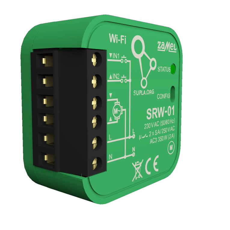
Zamel supla SRW-01 User manual

Zamel

Zamel supla SRW-01 User manual

Zamel RNK-02 User manual

Zamel

Zamel RNK-02 User manual

Zamel exta SRP-05 User manual

Zamel

Zamel exta SRP-05 User manual

Zamel Cet Ledix SLR-01 User manual

Zamel

Zamel Cet Ledix SLR-01 User manual

Zamel RTD-01 User manual

Zamel

Zamel RTD-01 User manual

Zamel NC60 User manual

Zamel

Zamel NC60 User manual

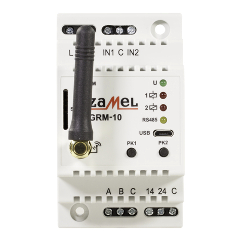
Zamel GRM-10 User manual

Zamel

Zamel GRM-10 User manual

Zamel exta life ROB-21 User manual

Zamel

Zamel exta life ROB-21 User manual

Zamel Exta RTM-02 User manual

Zamel

Zamel Exta RTM-02 User manual

Zamel RTD-02 User manual

Zamel

Zamel RTD-02 User manual

Zamel RNK-02 User manual

Zamel

Zamel RNK-02 User manual

Zamel exta RTM-20 User manual

Zamel

Zamel exta RTM-20 User manual

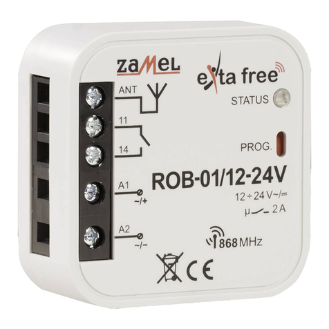
Zamel Extra Free ROB-01/12-24V User manual

Zamel

Zamel Extra Free ROB-01/12-24V User manual

Zamel Extra Free RZB-02 User manual

Zamel

Zamel Extra Free RZB-02 User manual

Zamel RTP-01 User manual

Zamel

Zamel RTP-01 User manual

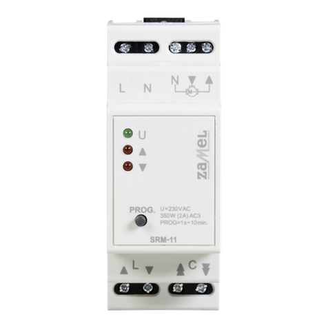
Zamel exta SRM-11 User manual

Zamel

Zamel exta SRM-11 User manual

Zamel RNK-02 User manual

Zamel

Zamel RNK-02 User manual

Zamel ledix SLR-11 User manual

Zamel

Zamel ledix SLR-11 User manual

Zamel Wi-Fi supla ROW-02 User manual

Zamel

Zamel Wi-Fi supla ROW-02 User manual

Zamel Extra Free ROB-01/12-24V User manual

Zamel

Zamel Extra Free ROB-01/12-24V User manual

Zamel RZB-05 User manual

Zamel

Zamel RZB-05 User manual

Zamel exta life SRM-22 User manual

Zamel

Zamel exta life SRM-22 User manual

Zamel SRP-02 User manual

Zamel

Zamel SRP-02 User manual

Zamel Extra Free RZB-02 User manual

Zamel

Zamel Extra Free RZB-02 User manual

Popular Controllers manuals by other brands

Eurotherm 2416 Installation and operation handbook

Eurotherm

Eurotherm 2416 Installation and operation handbook

thomann BOTEX SDC-6 user manual

thomann

thomann BOTEX SDC-6 user manual

iNels RF KEY quick start guide

iNels

iNels RF KEY quick start guide

Objective Imaging OASIS-4i installation guide

Objective Imaging

Objective Imaging OASIS-4i installation guide

bluelab Pro Controller Wi-Fi user manual

bluelab

bluelab Pro Controller Wi-Fi user manual

Afag SIGA B.7/65.1 V6 Operating and installation instructions

Afag

Afag SIGA B.7/65.1 V6 Operating and installation instructions

KM SVS2000 Installation & operation manual

KM

KM SVS2000 Installation & operation manual

Doepke DFA Series operating instructions

Doepke

Doepke DFA Series operating instructions

Vexve AM20-W Setup and user guide

Vexve

Vexve AM20-W Setup and user guide

Gamma Vacuum DIGITEL instruction manual

Gamma Vacuum

Gamma Vacuum DIGITEL instruction manual

National Instruments cRIO-9064 user manual

National Instruments

National Instruments cRIO-9064 user manual

Moxa Technologies ioThinx 4530 Series Quick installation guide

Moxa Technologies

Moxa Technologies ioThinx 4530 Series Quick installation guide

BENDIX EC-60 ABS-ATC ESP CONTROLLERS ADV introduction

BENDIX

BENDIX EC-60 ABS-ATC ESP CONTROLLERS ADV introduction

Crouzet Millenium Evo Series quick start guide

Crouzet

Crouzet Millenium Evo Series quick start guide

Leviton NE505 installation instructions

Leviton

Leviton NE505 installation instructions

Omega i Series user guide

Omega

Omega i Series user guide

Festo LR G Series operating instructions

Festo

Festo LR G Series operating instructions

PowerLed BLE-DIM instructions

PowerLed

PowerLed BLE-DIM instructions

manuals.online logo
manuals.online logoBrands
  • About & Mission
  • Contact us
  • Privacy Policy
  • Terms and Conditions

Copyright 2025 Manuals.Online. All Rights Reserved.