Plus N-314 User manual

1
Copyboard
N-314
SERVICE MANUAL
9/1.2016. Ver.1.1

2
CONTENTS
1. COMPLIANCE OF SAFE REPAIR ........................... 3
1-1. Cautions during Product Movement ....................3
1-2.
Cautions during disassemblying and assembling
...3
2.
SPECIFICATIONS
.....................................................4
2-1. Product Specications
...........................................4
2-2. Names of the Parts...............................................5
2-3. Control Panel .......................................................7
2-4. Numeric Panel
.....................................................8
2-5. Meaning of Error Messages ................................9
3. TROUBLE SHOOTING ............................................10
4. DISASSEMBLY AND ASSEMBLY ............................12
4-1. Tolls Required ......................................................12
4-2. Caution.................................................................12
4-3. Disassembly and Assembly Procedures .............10
4-4. Disassembly and Assembly ................................13
5. ADJUSTMENT...........................................................19
5-1. Calibration..........................................................19
5-2.
Changing the Internal Program of N-314 Main Set
....20
5-3. Test mode...........................................................21
6. DEVICE SETTING.....................................................22
6-1.
Basic setting operation
...........................................22
6-2.
T
able of Function Numbers and Setting
.................23
7. CABLE AND CABLE CONNECTION .....................25
8. PARTS LIST ............................................................26
1. PANEL SIDE ..........................................................26
2. MAIN BOARD CIS UNIT CABLE ...........................28
3. SHEET FRAME .....................................................30
4. ACCESSORIES .....................................................32
5. CARTON ...............................................................34
6. N-31-T
...................................................................36
7. N-18/N-20-T(USA Only) ........................................38
8. SCREWS & WASHERS ........................................40

3
1. COMPLIANCE OF SAFE REPAIR
Be sure to read this Service Manual before providing services. In the PLUS Copyboard, full consideration is taken
to ensure the safety for a re, electric shock, injury, harmful radiation, and substance. Therefore, observe the notice
described in this Service Manual so that the safety is kept when providing services. Moreover, be sure to observe the
notice described in the User’s Manual.
Pay attention to the following during service inspection.
1-1. Cautions during Product Movement
• It is necessary to remove the products when making the service of products put on the wall. At that time,
hold the product by two or more persons to prevent the product from dropping or a person from falling down.
1-2. Cautions during disassembling and assembling
1. When doing repairs, make sure that power plug is pulled out to insure safety.
2. Make sure that parts and screws and wiring, etc. are returned to their original positions. Tube, tape and other
insulation materials have been used for safety reasons. The internal wiring has been designed to avoid direct
contact with hot parts or parts under high voltage when using clamps or other tools.
3. The parts used in this device have special safety features such as ame-resistance and anti-voltage properties.
When replacing parts, always use parts supplied from the factory.
4. After nishing operations make sure that all parts and wires have been returned to their original position and that
there has been no deterioration of the area around the location that was worked on.
5. Be sure to use an earth band (wrist band) during repair and inspection.
6. Aluminum is used for this product as materials. During assembling and disassembling, be careful not to mistake the
type of screws. Depending on the screw used, the screw hole is damaged and parts may be unable to be xed
properly.
CAUTION: Never remove the two tension plates at the top and
bottom because they x a spring.
Tension Plate

4
2.SPECIFICATIONS
BOARD TYPE (Model name)
2-1. Product Specications
Standard (N-314)
Self-standing (T-shaped legs), or wall mounting
W1480 × D675 × H1947*² mm
Installation method
IExternal dimensions
(T-shaped legs*¹)
Form
Main unit weight
T-shaped legs weight
Panel size
Effective reading size
Number of Pages
Paging
Drive method
Reading method
Reading illumination light
source
Reading resolution
Reading time
Board
I
nterface
Added functions
Power supply
Operating
conditions
Operating
environment
Miscellaneous Ruled lines
Miscellaneous
50 mm cross-ruled squares
Dedicated markers (black, red, blue, and green)
Remarks
*1: The height is adjustable at 1747, 1847 and 1947 mm.
*2: The value indicated for “H” (height) is the maximum height.
*3: Not including the weight of the printer.
*4: USB Memory device not included. The memory capacity corresponds to 32GB or less.
*5: Some printer may not be compatible.
•
Please note that for quality improvement purposes, specications and design are subject to change without prior notice.
AC power adapter
File format
Type
Compatible FAT types
Printing resolution
LAN port
Supported protocol
Interface
No. print colors
Clock
Web browser
PC consumption
Printer interface
Supported network
printer
Screen size
Board
Printing
Network
External
memory
PC connection
Temperature:
Humidity:
10–35°C
30–85% (No condensation)
JPEG,PNG,PDF
Eight colors or two color monochrome
FAT 16, 32 *4
300 dpi or equivalent
USB Flash memory
USB2.0
Conforming to USB 2.0 standards / LAN port
FTP supported printer *5
Used for the timestamp and for le dating properties
Windows :Internet Explorer 8.0 or greater
Macintosh : Safari 5 or greater
* Enable JavaScript
Images can be acquired and device settings made via USB (using a browser)
RJ-45(10Base-T/100Base-TX)
TCP/IP (FTP/FTPS, HTTP/HTTPS, DHCP, NetBIOS Name Service)
In standby: 3W, During operation: 12W (not including printer)
12.5 kg
25 kg*³
H910 × W1300 mm
RGB,LED
Main scanning direction (vertical sheet surface) 1.92 dots/mm (50 dpi or equivalent)
Sub scanning direction (horizontal sheet surface) 1.92 dots/mm (50 dpi or
equivalent)
Input : AC100–240V/50–60 Hz, Max 0.75 A
Output : DC 12 V, 3.0 A
Black & white: approx. 15 s
Color: approx. 15 s
Standard type: 2458 x 1728 dots (xed)
Wide type:
3418 x 1728 dots (xed)
Bi-directional, endless (Horizontal scrolling)
4
Sheet movement
CIS (Contact Image Sensor)
H900 × W1280 mm

5
2-2. Names of the Parts
Front
SPECIFICATION
Main Unit
Sheet
Dedicated markers are used on the Sheet to
draw diagrams and to write.
Control Panel
Input/output terminals
(see next page)
* Located on the bottom surface.
Printer Table
The printer* is placed here. (See the Assembly
and Setup Manual.)
* The printer is sold separately.
AC Adapter Box
Store the AC Power Adapters of the Copyboard
and printer here. (See the Assembly and Setup
Manual.)
Stand
This Stand supports the Copyboard. (See the
Assembly and Setup Manual.)
Frame Cover
Pen Tray
* Depending on the product you have purchased, the printer may be
sold separately.
* This illustration does not show the connection cords.
Effective Reading Size
The area that can be copied is the gray area of
the diagram.
Note:
It might not be possible to print or copy
when storing to USB Memory or personal
computer any portions that are drawn outside
of this range.
approx. 10 mm
approx. 10 mm
Effective reading size
approx. 5 mm
approx. 5 mm
Numeric Panel

6
SPECIFICATION
Input/output terminals
Caster
Unlock
Lock
Locking/unlocking the stand's Casters
After installation, Lock the Casters with the stoppers. When
moving the stand, Unlock the Caster's stoppers.
The stoppers are locked when the bottom is pressed. Press
the top to Unlock them.
Personal computer (PC) dedicated USB
port (Type B)
Connect this with the USB port (type A) of the PC.
Personal computer (PC) dedicated USB port (Type B)
Used to connect the Copyboard to a computer to
make the Copyboard's device settings. Can also be
used to copy scanned images onto the computer.
DC input connector
Connect this with the DC plug end of the AC
Power Adapter. (Only connect the supplied AC
Power Adapter; nothing else.)
Printer connector (USB port Type A)
Connect this with the USB connector of the printer.
(The printer connector is dedicated for use with a
printer; use
it only with a printer.)
The connector is located on the bottom surface
of the Main Unit.
The diagram view is seen from the bottom.
* This illustration does not show the printer or
connection cords.
USB B
PC
USB A
MEMORY
MADE IN CHINA
SER.No.
I N P U T : 12V 3.0A
FACTORY
: SPI
MODEL : N-314
COPYBOARD
Pleaseconnectdedicated
orrecommendedprinter.
PRINTER
DC12V
LAN terminal (RJ-45)
Connect a commercially available LAN cable.
USB memory port (type A)
Connect a commercially available
USB
memory device here. Scanned
images
can be saved.
Rating label
(Serial number)
The figure is viewed from the back.

7
SPECIFICATION
2-3. Control Panel
When pressing a button, please press the center area (the square bulge). The button may not work if it is pressed on a corner.
N-314
Setup
Thumbnall
Continue
Number of Copies
Network
Save
Network Print On Board Print
Scroll/Stop Scroll/Stop
Color / B/W
ON/Standby
USB
Color Print
7 Network ( ) button
Scrolls and scans the sheet one screen’s worth and saves
the data in the folder for saving.
The data is saved either on the copyboard or in a folder on the
FTP server, as previously set.
• If you have set “Plural Registration”, go on to enter another
ID number using the keypad panel. For details, refer to “N-314
Series Network Manual”.
8 Save ( ) button (USB memory storage)
The sheet is moved by 1 screen and read, and the image is stored
on the USB Memory device.
When connected to a computer by USB Cable, the image is stored
in the Copyboard's internal memory.
9 Network Print ( ) button
The sheet is moved by 1 screen and read, and the image is printed
out to the network printer on the same network.
The number of copies is displayed on the display window.
* FTP supported printer
10 On Board Print ( ) button
The sheet is moved by 1 screen and read, and the image is
printed out to the printer connected with the network board.
The number of copies is displayed on the display window.
11 Scroll/Stop ( ) button
When the button is pressed, the sheet scrolls one screen’s
worth to the left (to the next screen) and stops automatically.
When the button is pressed, the sheet scrolls one screen’s
worth to the right (to the previous screen) and stops automatically.
When pressed during scrolling, scrolling stops.
12 Color / B/W ( ) button
Changes print color (Color / Monochrome).
Selection status is shown according to whether the Color Print
status indicator is lit or off and how it lights.
Color: Green steady light
Monochrome: Off
13 USB A Memory port (USB Type A)
Saves in commercially-available USB memory images that have
been read by the network board.
The USB status indicator lights green when the USB memory
device is recognized.
14 Status
Connection setting status is shown by turning on/off the indicator.
For details, see pages 23 and 24.
1 ON/Standby button
Turns the Copyboard’s power on and off (standby mode).
2 Display window
The number of copies, operating status and error messages
are displayed on the 7-segment LEDs.
3 Continue ( ) button
Used to select the number of screens when printing or storing
multiple screens consecutively.
Model: N-314 (single and double screens)
4 Consecutive printing number indicators
These light yellow to indicate the number of screens
selected with the consecutive button.
5 Thumbnail ( ) button
Used to select the layout for printing thumbnails of multiple
screens on a single page.
The selected layout is indicated on the display window.
6 Number of Copies ( ) /Test print button
Press this button to set the number of copies to be printed
(max. 10). The number of copies is displayed on the display
window.
* " " is displayed during test printing.
5
1
2
5
9
7
11
12
14
13
10
8
6
4
3
USB B
PC
USB A
MEMORY

8
SPECIFICATION
2-4. Numeric panel
1
2
5
4
3
12
56
789
0
4
3
N-314
ESC
Touch the card here
ICCard
1 IC card read/write part
Touch the supplied IC card here.
Reads or writes data to the IC card.
Touch the touch mark with the IC card. Touching other
places than the touch mark may cause an error.
2 Numeric (0 thru 9) button
Enter the ID number for network storage.
3 Escape (ESC) button
Cancels entries on the keypad panel.
4 Enter ( ) button
Starts network storage.
5 IC Card indicator
Shows status of read/write to the IC card according to
whether it is lit or off and how it lights.
IC Card indicator Status of IC card
Lit green Accept IC card
• Turning on the power lights green.
Flashing green Preparing for writing to IC card
Lit red
IC card error in read/write (3 seconds)
Off
Not accept IC card
The indicator lights off in the following
condition:
• “Network Setting” is not done.
• “Network Storage” in “Security
Setting” is set to “Invalid”.
• In operation
When pressing the button, press the center area (the square bulge). The button may not work if it is pressed on a corner.

9
N-314
Network-related errors indicate errors in access between the network board and network. In some cases they are
related to thenetwork system, so consult the network administrator.
SPECIFICATION
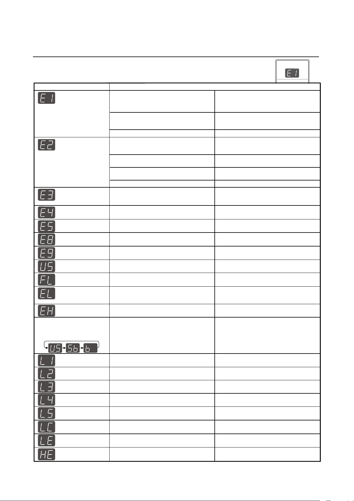
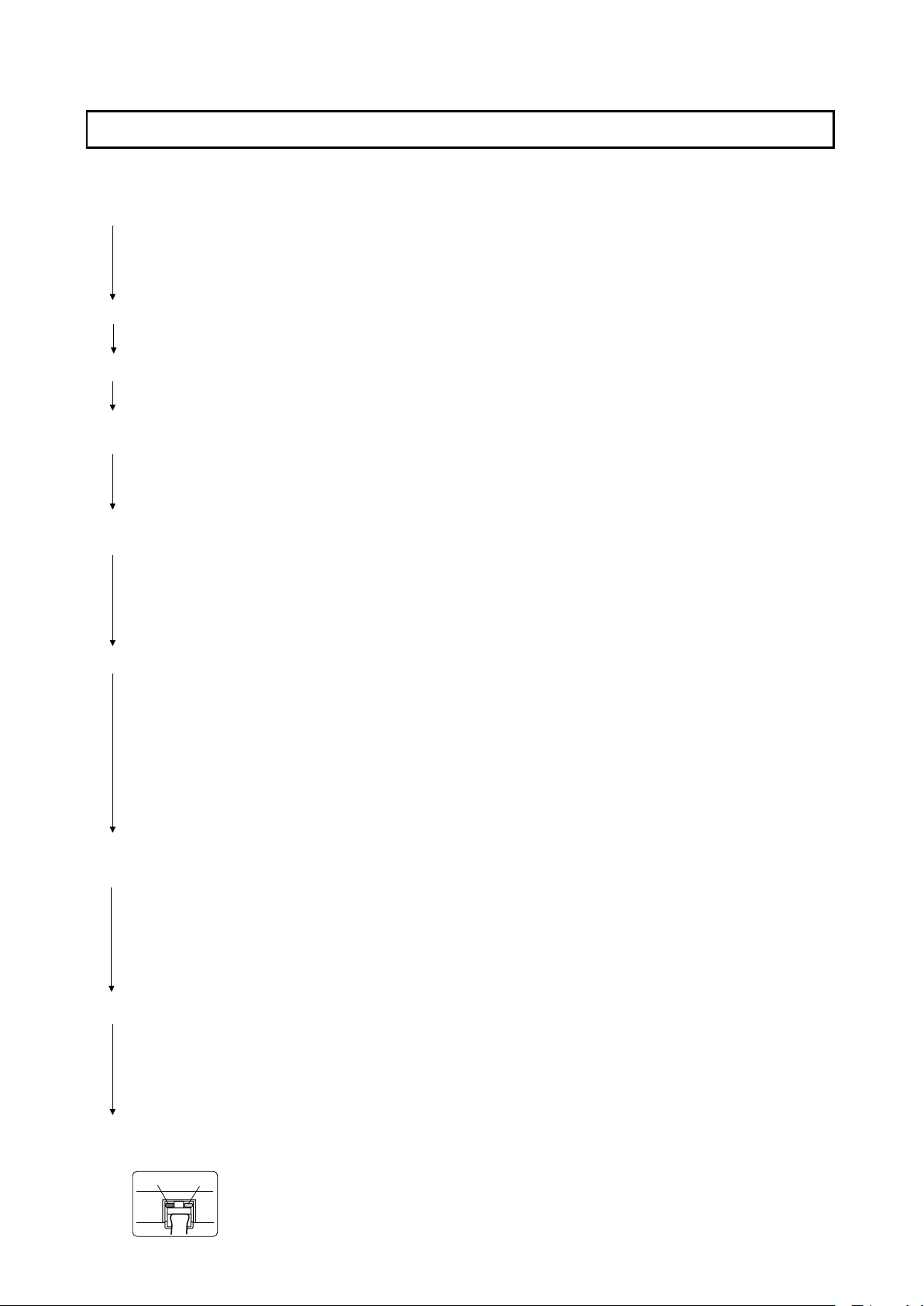
2-5. Meaninig of Error Messages
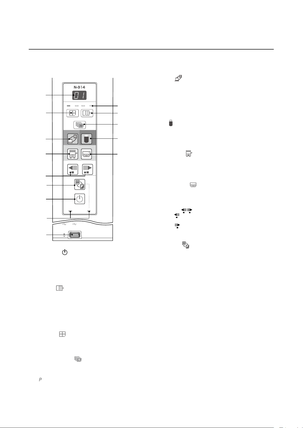
If any of the following ashing indications appear in the display window of the control
panel, please check the matters described below.
Error messages ash for 5 seconds, then stop ashing, remaining lit.
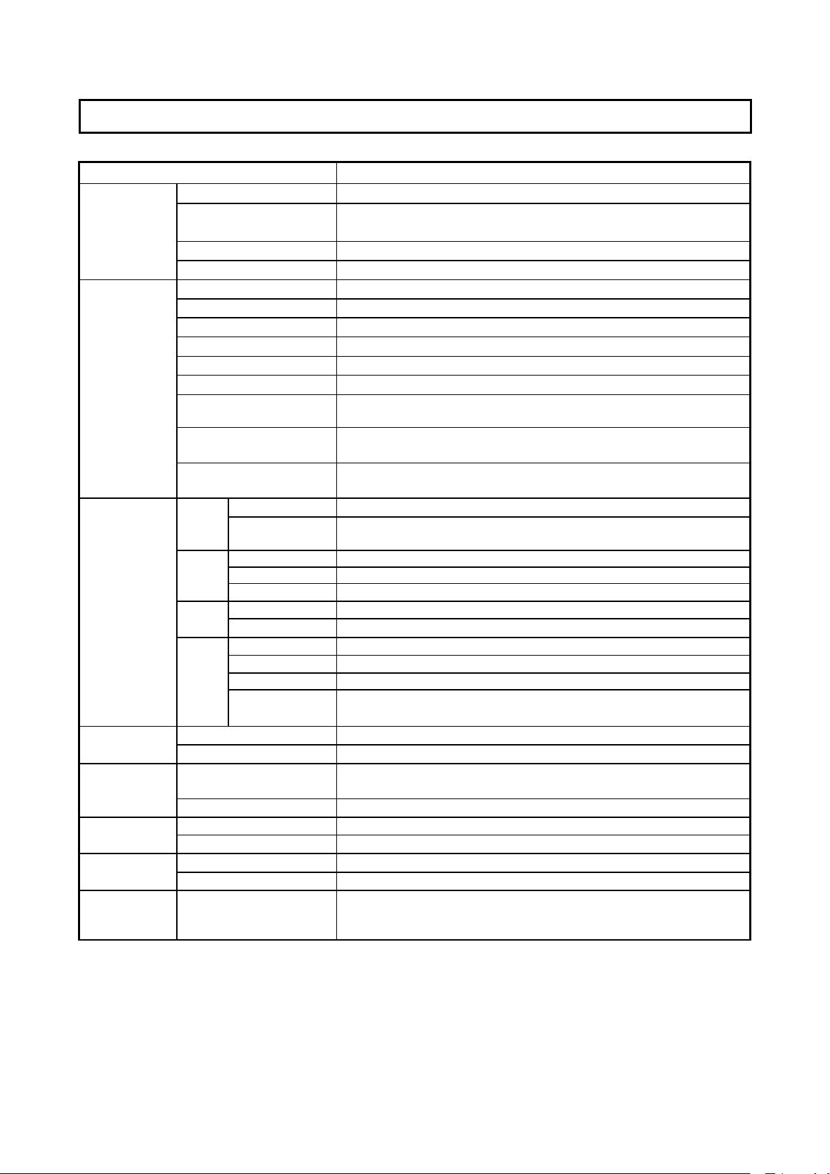
Problem and Solution
• Is the printer cable connected?
• Is power being supplied to the printer?
• When the printer uses an AC Power Ada-
pter, is the cable disconnected somewhere?
•
Check if the settings for FTP printing are correct.
• Has paper been set in the printer?
•
Is the printer error indicator ashing (or lit)?
• Is the USB Memory unformatted.
• Is a USB Memory that is not supported
by the Copyboard being used?
•
An error occurred during USB Memory st-
orage.
•
There is a lighting fault of the reading light
source, or a read signal error.
•
The operation is set to “Disable” in the
security settings.
• There is a Memory or internal fault.
• Coloring printing is set to “Disable”.
• USB Memory device is not plugged
into the Main Unit.
• There is no available space.
•
A printer that is not supported by the
Copyboard has been connected.
•
Did you press the ON/Standby button while
the USB Memory device was plugged into
the Main Unit?
•
A USB Memory device is plugged into the
main unit. When the USB Memory device
is disconnected, the power will be switched
off and the unit will enter the standby mode.
•
An error has arisen when setting the
time.
•
Unplug the power plug from the power
outlet and then plug it in again.
• Unplug the power plug from the power
outlet and then plug it in again.
•
Change the setting of the desired item to
“Enable”.
• Connect the LAN cable properly.
•
Input the correct user name and password.
•
No cable is connected to the LAN terminal.
• The user name or password is wrong.
• The FTP server’s IP address is wrong.
• There is no FTP storage folder.
• An error other than one indicated by L1
to L4 has occurred.
• The FTP printing error has occurred.
• An error has occurred in resetting the
network settings.
• This occurs when the size of the inserted
image is too large.
• Consult the network administrator then
set the FTP server’s IP address.
• Consult the network administrator then
set the FTP storage folder.
• Unplug the power cord from the power
outlet then plug it back in.
•
The network reset number is wrong. Input
the correct number and repeat the operation.
•
Adjust the image then repeat the operation.
operation.
•
C
hange the color printing setting to “Enable”.
•
Plug the USB Memory device into the
USB port.
•
Please delete unnecessary data using
a personal computer.
•
Start setting the date/time over from
the beginning.
•
Press the ON/Standby button and switch off
the power. When a record is required, switch
on the power and save to USB Memory.
•
Is the USB Memory device plugged in fully?
• Is the USB Memory damaged? —
• This unit supports the FAT and FAT 32
formats. Perform the formatting with
the personal computer.
•
The le formats for USB memory devices that
can be used on this copyboard areFAT and FAT32.
• Please check the operation with a
personal computer.
•
Please perform USB Memory storage again.
•
Do not insert or remove the USB Memory
during processing.
Printer not conne-
cted
No printing
paper Printer
problem
USB Memory
not recognized
USB Memory
storage problem
Reading problem
System error
USB Memory not
connected
Memory is full
Security
protection
Color printing
prohibited
LAN cable discon-
nected
FTP server recog-
nition error
FTP server conne-
ction failure
Network settings
reset errorfailure
Header/footer
writing errorfailure
FTP server writing
failure
IP address not set,
other network error
IP address not set,
other network error
Time setting error
When the “USB” letter
display is flowing...Warning
that disconnection of USB
Memory has been forgotten
An unsupported
printer is conne-
cted
•
Connect the printer properly and sw-
itch on the printer power.
•
Turn the power of the printer off and th-
en on again, and load the printer with
A4 or Letter size paper.
• Read the printer instruction manual.
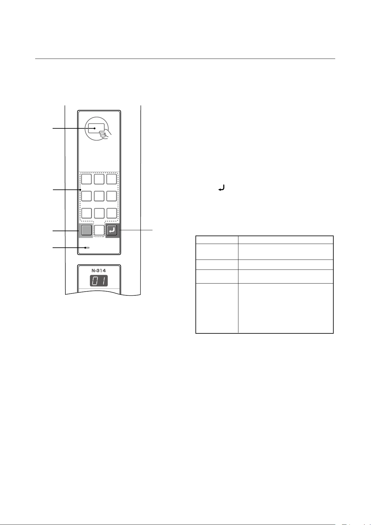
Error Display Number

10
By checking operations, it is possible to carry out judgments on malfunction to a certain extent. Carry out the following
checks before disassembling the equipment.
1. Press the Standby (On) button and turn on the power.
Is the power turned on?
2. Press the Scroll / Stop button.
Does the sheet operate normally?
3. Press the Print button (when a printer is used).
Does the error display (E1) appear?
4. Press the Save button (when a USB Memory is used).
Do the error displays (E2, E3 and US) appear?
5. Conrm the Main board Assy and LAN Port, (RJ-45), LED display. (During network connection)
*The LED (green, orange) of a LAN port can be conrmed when you remove the cable cover of a main board.
The current communication state can be grasped by conrming the LED.
Is the object written in the board printed normally?
Is the object written in the board stored normally?
Does the Error display appear?
Flashing indicator keeps "rotating" sequentially.
No →
No →
No →
No →
Yes →
Yes →
Yes →
Yes
Yes
Yes
Yes
No
No
No
• The AC Adapter is disconnected from the wall outlet.
• The AC Adapter is defective.
• The Main Board Assy DC jack part is defective.
• The SW Board Assy is defective.
• The connectors of the SW Harness is disconnected.
• The connectors of the Motor Harness is disconnected.
• The loser of the Timing Belt, the slack.
• The Sheet Motor Unit is defective.
• The Main Board Assy is defective.
Printer failure. (See section 2-5. Error Messages)
• The printer is defective. (See the Instruction manual of a printer.)
• The power of a printer is not turned on.
• Printer paper is exhausted.
• A Printer is not connected denitely.
• The Main Board Assy is defective.
Error display: E2 is displayed. (See section 2-5. Error Messages)
• A USB Memory is not formatted.
• An incompatible USB Memory is used.
• A USB Memory is defective.
• A USB Memory port is defective.
Error display: E3 is displayed.
• Memory storage error: Repeat save operation again.
• The Main Board Assy is defective.
A part of image is displayed black.
• The Main Board Assy is defective.
• Misalignment of CIS Unit: Replace the CIS Unit for improvement.
• Foreign matter adheres to the CIS Unit.
An image (print) is rubbed.
• Deterioration of CIS Unit.
• The marker (written character) becomes blurred.
• The ink cartridge (Drum Unit) is exhausted.
A specic color is not printed or the printed color is improper (when a color printer is used).
• The ink of a printer is exhausted.
• The ink cartridge of a printer is defective.
black line is put in a picture.
• Foreign matter adheres to the CIS Unit.
• The CIS Unit is defective: Replace the CIS Unit for improvement.
An image is rubbed.
• Deterioration of CIS Unit.
• The marker (written character) becomes blurred.
•
When a network can be connected normally →
Green blinks, Orange Off (During 10Base-X)
•
When a network can be connected normally →
Green blinks, Orange Lit (During 10Base-X)
• When a network cannot be connected
→Green Off, Orange Off (During non-connection
such as disconnection the LAN cable)
The error display (E5) appears. (See section 2-5. Error Messages)
• The Main Board Assy is defective.
• The SW Board Assy is defective.
3.TROUBLE SHOOTING
Orange Green

11
6. Conrm the LED display of the Numeric Panel Unit (during network connection).
*Conrm that a network is set so that an IC card can be used.
Bring an operation conrmation IC card (not including any data) in touch with an IC card reader/writer.
• Does an IC card indicator light (in the order of ①green →② red →③ green)?
No →The Numeric Panel Unit is defective.
Yes →Normal operation
→Test/adjustment mode segment display: <A.P>
Press any numeric key.
No →The Numeric panel cable is disconnected.
The Numeric Panel Unit is defective.
Yes →Normal operation
*Are numeric characters changed in a test/adjustment mode using a numeric button (of 0 to 9)?
• Insert the plug of an AC adapter into the main set to apply an electric current (in the Standby state).
• Press the “Save” button three times while pressing and holding the “Power” button.
TROUBLE SHOOTING
12
5
ICカード
6
789
0
4
3
ESC
Touchusingacard.
PLUS
cardICCard
ICcard
0
ESC
ICcard
0
ESC
ICcard
0
ESC
Touchusingacard.
①Green ②Red ③Green
N-314
12
56
789
0
4
3
ESC
N-314
T
est/adjustmentmode<A.P>
Setup
Setup
Thumbnall
Continue
・Pressanykeypad. Displayondisplaywindow
(Numericcharacter)

12
4-1. Tools Required
• Phillips screwdriver (+) No. 2
• Phillips screwdriver (–)
4-2. Caution
• See “1. Compliance of Safety Repair and Safety Inspection” before disassembling and assembling.
• Put on gloves so that you do not cut your hand at the sharp edge of a frame during disassembly and assembly.
• See “7. Wiring Diagram” and “8. Parts List” for the parts name or wiring.
• The point especially requiring attention when handling parts or performing disassembly and assembly contains a
caution. Be sure to follow this caution.
4-3. Disassembly and Assembly Procedures
4.DISASSEMBLY AND ASSEMBLY
START
Sheet Frame Unit
Frame CAP
USB Board
Panel Side (L) Panel Side (R)
Back Panel Unit
Numeric Panel Unit
Switch Board
CIS Unit
Rear Frame
Panel Front
Panel Rear (U)
Panel Rear (L)
Main Board Assy

13
4.4. Disassembly and Assembly
This section describes one example of disassembly and assembly procedures. For the actual operation, disassemble
and assemble the required parts with reference to “4-3. Disassembly and Assembly Procedures”.
* Remove the main set from the stand and proceed with the Endless Sheet. (Perform the operation on a mat.)
* Remove the Pen Tray before performing the procedure below.
1) Remove the Main Board Assy. (See Figs. 1 and 2.)
1.Remove the”S-1" screws shown in the figure 1 and then
remove the Cable Cover.
2.Remove the”S-1" screws shown in the figure 2 and then
remove the Main Board Shield.
Note:
If a screw is tightened too tightly, a screw hole may be
broken.
3.Disconnect the connector (CN1,2,3,6) connected to the
Main Board Assy shown in the gure 3.(See Figs. 3 and 4,5.)
4.Remove the”S-1" screw shown in the figure 4 and then
remove the Main Board Assy from the Main Board Shield.
5.When replacing the Main Board Assy shown in the gure 5,
insert the Main Board Assy from the oblique direction so
that the parts mounted at the rear of the Main Board Assy
are not damaged.
Fig.1
Fig.4
Fig.2
Fig.3
Fig.5
DISASSEMBLY AND ASSEMBLY
S-1
Main Board Assy
S-1
Cable Cover
S-1
Main Board Shield
CN1
CN2
CN3
CN6
Main Board Assy

14
3) Remove the Frame Cap. (See Fig. 9.)
1.Remove the “S-2” screws shown in the figure 9 and then
remove the Frame Cap.
4) Remove the Panel side L. (See Fig. 10)
1.Remove the “S-4” screws shown in the gure10.
Disconnect the connector connected to the Switch Board
and then remove the Panel Side L.
DISASSEMBLY AND ASSEMBLY
Fig.7
Fig.10
Fig.8
Fig.6
Fig.9
2) Remove the Frame Cap PC. (See Fig. 6.)
1.Remove the “S-2” screws shown in the gure 6 and then
remove the Frame Cap PC.
2.Disconnect the connector connected to the USB Board
shown in the gure 7.
3.Remove the “S-3” screws shown in the gure 8 and then
remove the USB Board.
Note:Fix an insulating sheet to the screws when installing the
USB Board Cover.
CN1
USB Board
USB Board Cover
USB Board
S-3
USB Board Cover
Frame Cap
S-2
S-4
S-4
Panel Side L
S-2
Frame Cap PC

15
8) Remove the SW Board. (See Fig. 15.16)
1.Remove the SW Panel shown in the gure15.
2.Slide the white protrusion (resin) at the rear of a SW Panel from the top of the SW Panel surface to the bottom
while pushing it with fingers.
7) Remove the Back Panel Unit. (See Fig. 14)
1.Remove the “S-5” screws shown in the gure12.
Remove 2 screws which are located on both sides of the Back Panel center.
2.Slide the Back Panel and remove it while pushing the Back Panel Unit corner shown in the gure 13 forward.
5) Remove the Panel Side R. (See Fig. 11)
1. Remove the “S-4” screws shown in the figure 11 and
then remove the Panel Side R.
7) Remove the Numeric Panel. (See Fig. 14)
1.Push the (ve) hooks of the resin shown in Figure 14 and
remove the Numeric Panel Unit on the front side.
2.Disconnect the connector of a Numeric panel cable.
DISASSEMBLY AND ASSEMBLY
Fig.12
Fig.15
Fig.13
Fig.16
Fig.14
Fig.11
S-4
S-4
Panel Side R
S-5
Back Panel Unit
Back panel Center
pushing
connector
slide
protrusion
N-314
SW Board
Setup
Thumbnall
Continue
Number of Copies
SW Panel
USB
保存
N-314
Setup
Number of Copies
Network Print On Board Print
Scroll/StopScroll/Stop
Color / B/W
ON/Standby
Color Print
Network Save
Thumbnall
Continue
N-314
Numeric Panel Unit
Connector
Setup
Thumbnall Continue
(five)hooks

16
DISASSEMBLY AND ASSEMBLY
Fig.19
Fig.17 Fig.18
Fig.21 Fig.22
Fig.20
9) Remove the CIS Unit. (See Fig. 19.20)
1.Disconnect the CIS Cable (FFC), shown in the gure 16, from a connector.
2.Remove the “S-2” screws shown in the gures19 and 20 and then remove the CIS Unit.
* At that time, operate while holding it with hands so that the CIS Unit does not fall.
Pay attention to the top and bottom when installing the CIS Unit.
* The CIS Unit with a CIS Support (see Fig. 22) is located in the upper position.
* When a CIS Unit is replaced, be sure to perform White level calibration.
See page 21 3.White level calibration
3.Remove the “S-3” screws shown in the figure
17 and then remove the SW Board.
Note: Pay attention to the wire drawing of the SW Cable
during assembling.
1.Put the protrusion from the bottom of the SW Panel when
returning the SW Panel to the former position.
2.Slide the protrusion in the direction indicated by the arrow.
3.Conrm that the hook of the SW Panel is completely put in
the notch of the Panel Side (L).
S-3
SW Board
CIS Unit
CIS Cable
CN1
S-2
S-2
CIS Support
USB
Number of Copies
Network Print On Board Print
Scroll/StopScroll/Stop
Color / B/W
ON/Standby
Color Print
Network Save
Hook
ステータス
USB
ON/Standby
Color Print
N-314
Setup
Thumbnall
Continue

17
11) Remove the Panel Upper. (See Fig. 24)
1.
Remove the “S-4” screws shown in the gure 24 and
then remove the Panel Front.
12) Remove the Panel Rear.
(See Fig. 25.26)
1.Remove the “S-4” screws shown in the figure 25 and then
remove the Panel Rear (U).
2.Remove the “S-4” screws shown in the figure 26 and then
remove the Panel Rear (L).
DISASSEMBLY AND ASSEMBLY
Fig.24
Fig.23
Fig.26
Fig.25
10) Remove the Rear Frame. (See Fig. 23)
1.Remove the “S-6” screws shown in the gure 23 and then
remove the Rear Frame (two).
Rear Frame
This sideis
locatedupwards.
S-6
Panel Front
S-4
S-4
Panel Rear (L)
S-4
PanelRear (U)

18
DISASSEMBLY AND ASSEMBLY
13) Replace the Endless sheet.
1.Remove the “S-2” screws shown in the gure 27.
2.Remove the Panel Plate shown in the gure 28.
3.Remove the stopper “S-4” screws in the (two upper and lower)
Tension Roller Bases shown in the gure 29.
4.Push the Tension Roller Base block shown in the gure 30 into the inside and x the Tension Roller Bases.
Notes:
• Be careful not to damage or fold it when handing the Endless Sheet.
• Replace it by two persons during replacement of the Endless Sheet.
Fig.28Fig.27
S-2
S-2
Panel Plate

19
Verticalline(black)
Cleaningplace
Cleaningplace
5. ADJUSTMENT
5-1. Calibration
[Calibration]
[Preparation]
Enter a vertical line (black) between the upper and lower ends of an Endless Sheet.
* Clean the (both sides of) endless sheet and then perform calibration.
[Calibration mode]
• Insert the plug of an AC Adapter into the main set so as to apply an electric current (in the Standby state).
• Press the Save button three times while pressing and holding the Power (ON/Standby) button.
Segment display in test adjustment mode: <AP>
• Press the Feed/Stop button. Segment display: “01”.
• Press the Save button.
• Segment display appears when the Endless Sheet rotates for normal termination: <AA>
1) Calibration is started, ·······························································<1. >
2) Initialization,··············································································<1.0>
3) The rst vertical line is being detected,····································<1.1>
4) The vertical line after one cycle is being detected,···················<1.2>
5) When no vertical line can be detected, and······························<1.2.>
6) When calibration succeeds·······················································<AA >
Calibration is required in the following cases.
• When a Main Board Assy is replaced
• When a Sheet Frame Unit is replaced
For the replacement of a CIS Unit in the market, usually, use a unit that has been adjusted at a factory.
* Be sure to replacing the CIS Unit when any failure occurs in an image.

20
5-2. Changing the Internal Program of N-314 Main Set
[How to rewrite program using PC]
Equipment used
1) Firmware data for N-314(PX26H_N314_**_**.brn)
2) PC main set (OS: Windows 7/8/8.1/10)
3) USB Cable
Preparation
Save the extracted N-314 program holder on the desktop screen of PC used.
1. Connect the PC and Copyboard main set using a
USB Cable.
2. Insert the plug of an AC Adapter into the DC jack of
the Copyboard main set and turn on the power.
3. A screen appears when the Copyboard is recognized
as a removable disk.
If any screen is not opened, open the removable
disk of the Copyboard using Explorer.
5. The display window of the Copyboard main set automatically changes to “UP” blinking display.
6. Press the Save button. The display window changes to rotation display. A program then begins to be rewritten.
7. Rewrite operation is completed when the display window changes to “AA” blinking display.
8. Pull out the plug of the AC Adapter once, turn on the power gain, and then conrm the version of rmware in a
test mode.
4.
Copy the firmware data “PX26H_N314
_**_**.brn
.
brn”,
to be updated, to the removable disk. (Drag & Drop)
ADJUSTMENT
File Edit View Favorites Tools Help
Back Search Folders
D:
/
Address Go
Removable Disk(D)
setup
Make a new folder
Publish this folder to the web
Share this folder
File and Folder Tasks
Other Places
Details
My Computer
My Documents
Shared Documents
My Network Places
File Edit View Favorites Tools Help
Back Search Folders
D:
/
Address Go
Removable Disk(D)
setup
Make a new folder
Publish this folder to the web
Share this folder
File and Folder Tasks
Other Places
Details
My Computer
My Documents
Shared Documents
My Network Places
UPIC
Recycle Bin
UPIC
Tounch&Draw
Adobe Reader
9
paint
PX,8L_01_...
Start Remoyable Disk (D:) 2:15 PM
EN
Table of contents
Other Plus Office Equipment manuals
Popular Office Equipment manuals by other brands

Stretch Now
Stretch Now Mobel Motion MK 2 user guide

Neopost
Neopost IM 30 Operator's manual

Eurobib Direct
Eurobib Direct Info Pod E4383 user manual

Canon
Canon Puncher Unit-BE1 Service manual

OfficeSource
OfficeSource EVH100BGG Assembly instructions

LDI Spaces
LDI Spaces Safco Onyx 6451 Assembly instructions