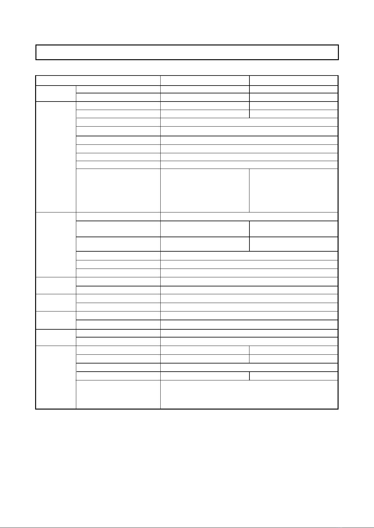
K-10S K-10W
W1480 x D675 x H1847 W1980 x D675 x H1847
W1300 x H910mm W1800 x H910mm
W1280 x H900mm W1780 x H900mm
2
External dimensions
weight
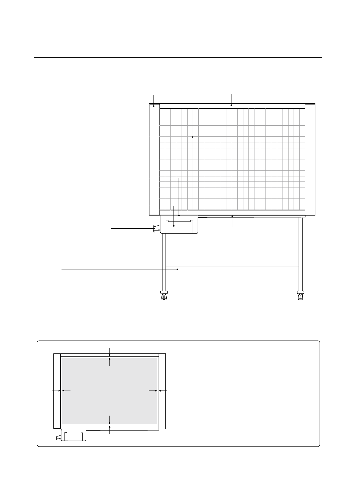
Board surface dimension
Effective reading dimensions
No. of board sufaces
Sheet feeding
Drive system
Reading method
Reading illumination light source
Reading resolution
Reading and printing time
(* Print time will vary according
to the amount of data.)
Reading method
Reading size
Reading paper size
Reading color
Print resolution
No. sheets printed
Clock
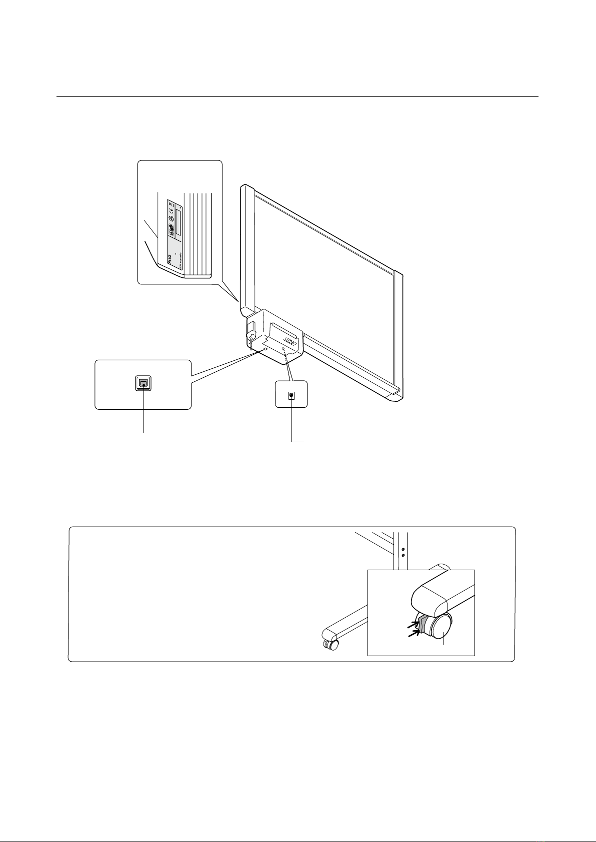
Computer connection
AC power adapter
Power consumption
Temperature
Humidity
Ruled lines
Writing tool
Equal ratio printing
2-sheet printing
Recording density adjustment
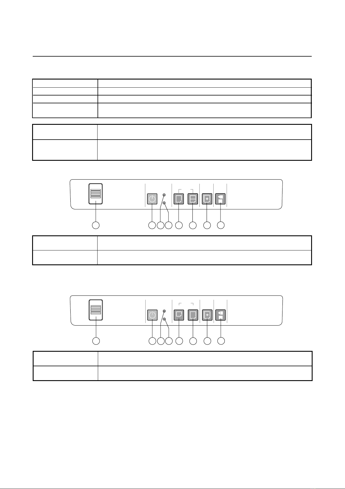
Manual board surface moving function
Accessories
○○
○
○
○—
Unidirectional, endless (Horizontal scrolling)
Sheet moving method
CIS (Contact Image Sensor)
RGB LED
1.92 dots/mm
A4 size (W210 x H297 mm) A4 size (W210 x H297 mm)
A4-L-size (W210 x H405 mm)
1-sheet printing
Approx. 10 seconds reading, approx.
11 seconds printing
2-sheet printing:
Approx. 20 seconds reading, approx.
22 seconds printing
1 sheet (A4 equal ratio), 2 sheets
compressed (A4 compression)
1 sheet (A4 compression, A4-L
equal ratio)
Thermal head thermosensitive recording
Monochrome
200 dpi
1 sheet
Used for time stamps
Device settings
Input: AC 100-240V, 50/60Hz, 1.5A Output: DC 24V, 2.5A
In power-saving mode: 1W Operating: 50W
10°C-35°C
30 to 85% (with no condensation)
50 mm grid
White board markers (black and red)
A4 compressed printing
Approx. 14 seconds reading, approx.
15 seconds printing
A4-L equal ratio printing:
Approx. 14 seconds reading, approx.
15 seconds printing
31.5kg 35.5kg
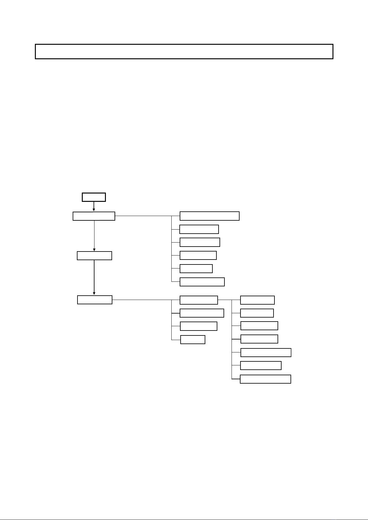
2.SPECIFICATIONS
2-1. Product Specications
Exterior
Board
Printer
Additional
functions
Power supply
Others
Functions
3 levels of adjustment in the device settings
Dedicated white board markers (back and red), dedicated eraser,
2 eraser replacement sponges, dedicated the rmosensitive paper
(30 m roll), AC power adapter (with 2.5 m power cord), instruction
manual
Usage conditions
BOARD TYPE (Model name)
*
Please note that product specications and appearance are subject to change without notice.