Plus BF-041S User manual

COPY BOARD
BF-041S/BF-041W
SERVICE MANUAL
SMH0061E-A

1. COMPLIANCE OF SAFE REPAIR ................................ 1
1-1.Cautions during Product Movement ........................ 1
1-2. Cautions during disassembling and assembling .... 1
2. SPECIFICATIONS ......................................................... 2
2-1. Product Specifications............................................ 2
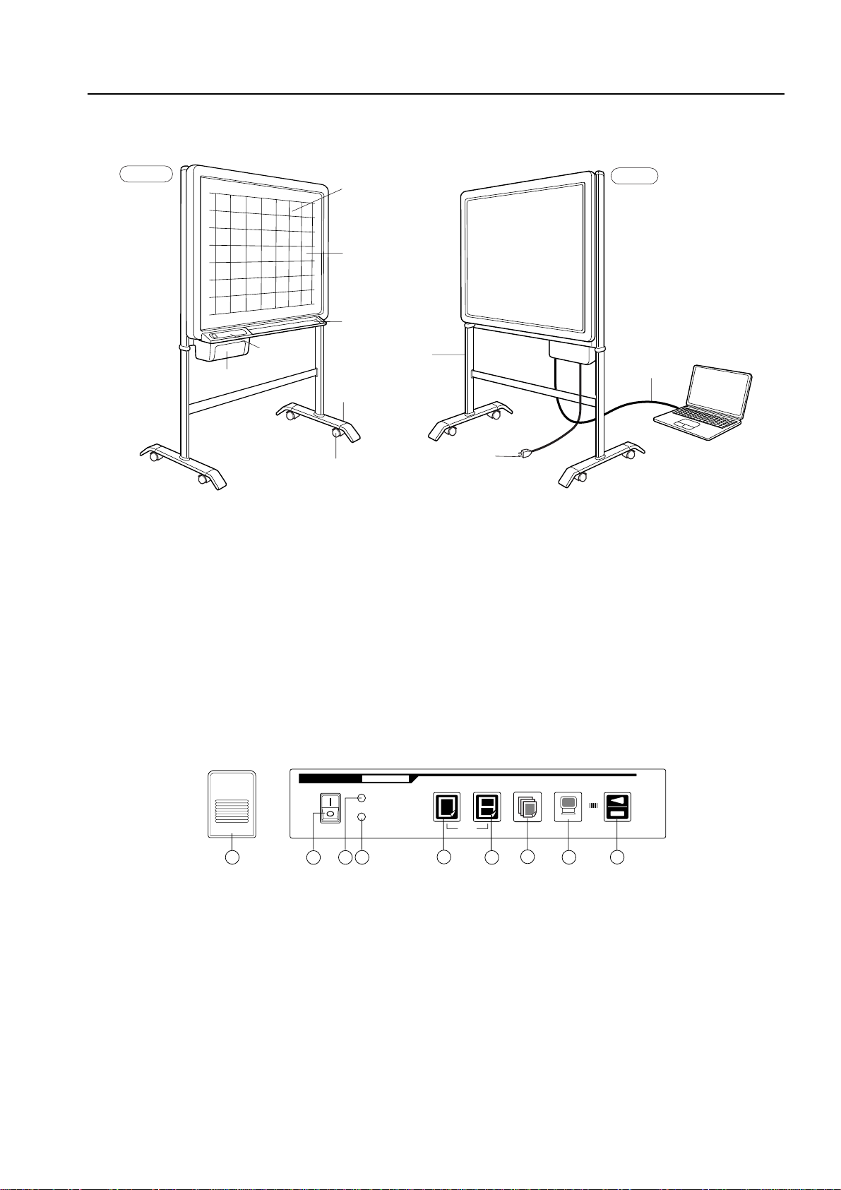
2-2. Location of Main Set............................................... 3
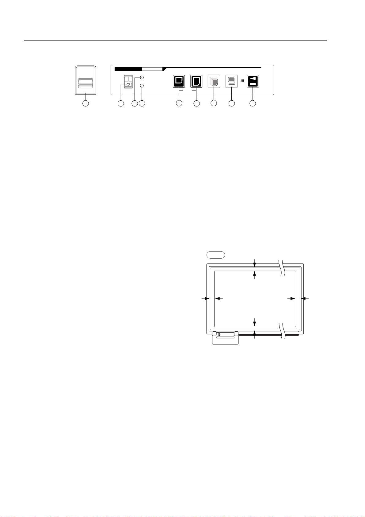
2-3. Operation Panel ..................................................... 4
2-4. Scanning Area ........................................................ 4
3. TROUBLE SHOOTING.................................................. 5
3-1. Trouble Shooting .................................................... 5
4. DISASSEMBLY AND ASSEMBLY ................................ 7
4-1. Caution ................................................................... 7
4-2. Tools needed .......................................................... 7
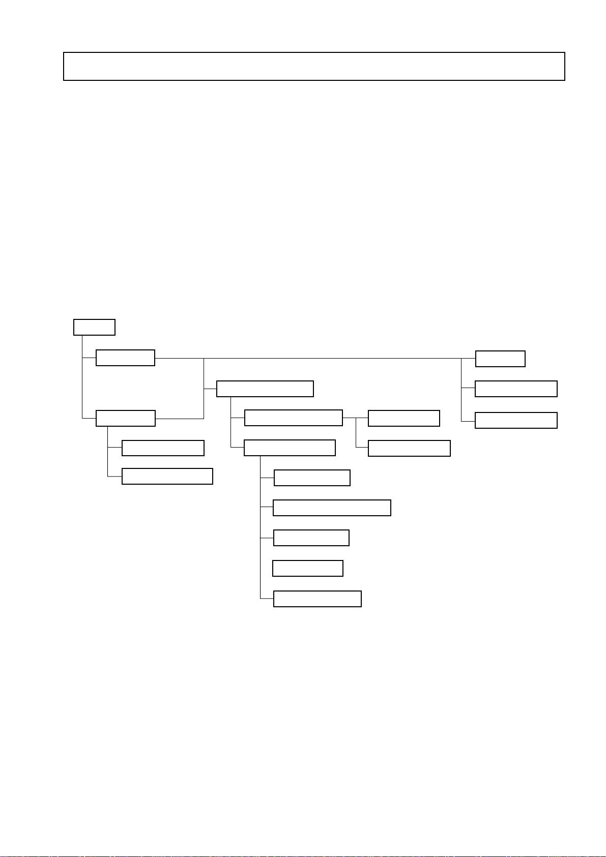
4-3. Disassembly and Assembly Order ......................... 7
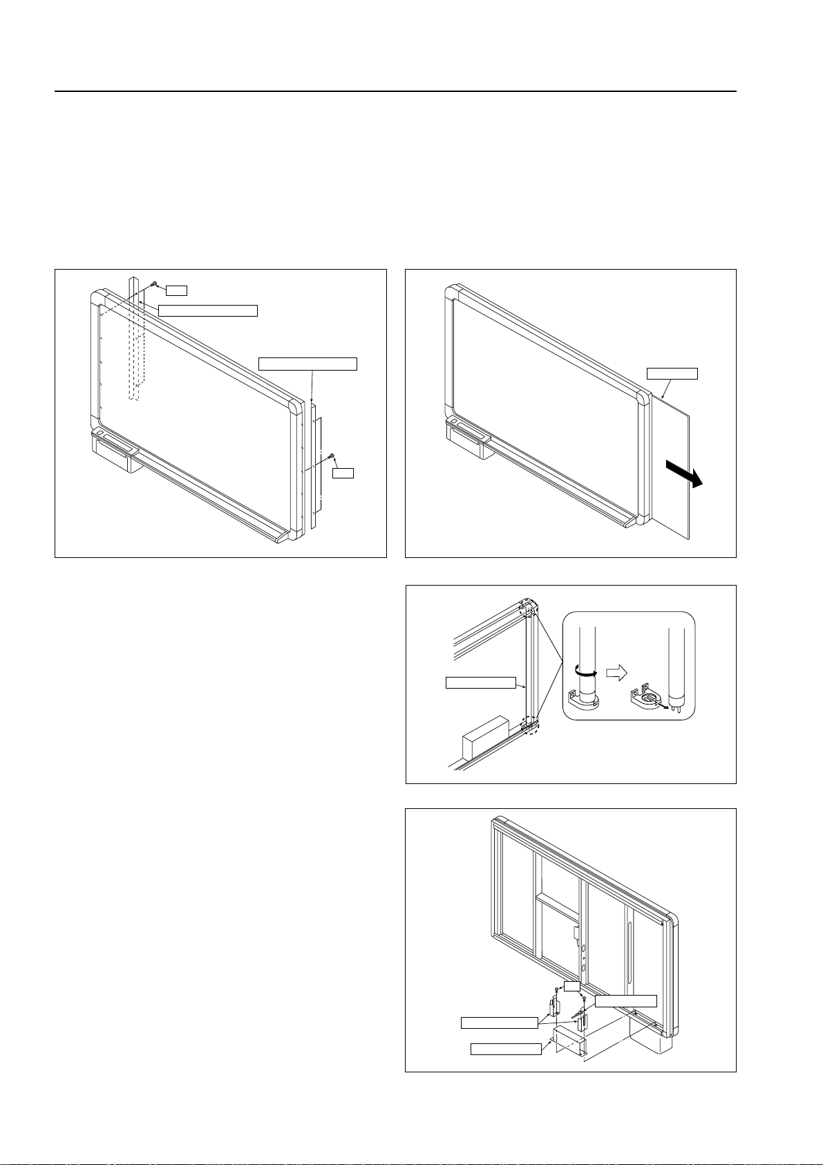
4-4. Disassembly and Assembly.................................... 8
5. ADJUSTMENT............................................................. 15
5-1. Quick Calibration .................................................. 15
5-2. Calibration ............................................................ 16
5-3. CCD Unit Adjustment ........................................... 17
5-4. TensionAdjustment of Timing Belt ....................... 22
6. CABLE AND CABLE CONNECTION ........................... 23
CONTENTS
7. PARTS LIST .................................................................. 24
7-1. BOARD UNIT SECTION (BF-041S)..................... 24
7-1. BOARD UNIT SECTION (BF-041W).................... 26
7-2. FRAME COVER SECTION (BF-041S) ................ 28
7-2. FRAME COVER SECTION (BF-041W) ............... 29
7-3. SHEET FRAME SECTION (BF-041S) ................. 30
7-3. SHEET FRAME SECTION (BF-041W) ............... 31
7-4. BOARD FRAME SECTION (BF-041S) ................ 32
7-4. BOARD FRAME SECTION (BF-041W) ............... 34
7-5. PRINTER UNIT SECTION 1(BF-041S/W) ........... 36
7-6. PRINTER UNIT SECTION 2 (BF-041S/W) .......... 38
7-7. STAND SECTION ............................................... 40
7-8. WALL MOUNTING SECTION .............................. 42
7-9. ACCESSORIES SECTION................................... 43
7-10. PACKING SECTION .......................................... 44
7-11. SCREWS & WASHERS SECTION .................... 46
8. SERVICE NOTE .......................................................... 47
8-1.
Replacement Procedure of Dedicated Recording Paper .....
47
8-2. Updating the Firmware ......................................... 48
8-3. Thermal Head Test ............................................... 51
9. REVISION HISTORY ................................................... 52

1
1. COMPLIANCE OF SAFE REPAIR
Be sure to read this Service Manual before providing services. In the PLUS Copyboard, full consideration is
taken to ensure the safety for a fire, electric shock, injury, harmful radiation, and substance. Therefore, observe
the notice described in this Service Manual so that the safety is kept when providing services. Moreover, be sure
to observe the notice described in the Instruction Manual.
Pay attention to the following during service inspection.
1-1. Cautions during Product Movement
·It is necessary to remove the products when making the service of products put on the wall.At that time, hold
the products by two or more persons to prevent the products from dropping or a person from falling down.
1-2. Cautions during disassembling and assembling
1. This equipment contains parts under high voltage. When doing repairs, make sure that power plug is pulled
out to insure safety.
2. Make sure that parts and screws and wiring, etc. are returned to their original positions. Tube, tape and other
insulation materials have been used for safety reasons. The internal wiring has been designed to avoid
direct contact with hot parts or parts under high voltage when using clamps or other tools.
3. The parts used in this device have special safety features such as flame-resistance and anti-voltage proper-
ties.
When replacing parts, always use parts supplied from the factory.
4. After finishing operations make sure that all parts and wires have been returned to their original position and
that there has been no deterioration of the area around the location that was worked on.
5. Be sure to use an earth band (wrist band) during repair and inspection.

2
2. SPECIFICATIONS
2-1. Product Specifications
Item Specification (BF-041S) Specification (BF-041W)
Board surface size W1300 x H920 mm W1800 x H920 mm
(51.2 x 36.2 inches) (70.9 x 36.2 inches)
Effective reading area W1240 x H880mm W1740 x H880mm
(48.8 x 34.6 inches (68.5 x 34.6 inches)
Number of pages 2 pages 2 pages
Sheet driving method One direction endless drive One direction endless drive
Grid 50 mm (2 inches) squares 50 mm (2 inches) squares
Writing instruments Dry Erase Whiteboard markers Dry Erase Whiteboard markers
(black/red/blue) (black/red/blue)
Reading method CCD sensor CCD sensor
Print method Thermal printing Thermal printing
Print density 8 dot/mm 8 dot/mm
Print paper Special thermal sensitive paper Special thermal sensitive paper
(30 m/98 ft roll) (30 m/98 ft roll)
Size of print paper A4 size (210✕297 mm) A4 size (210✕297 mm)
Letter size (8.5✕11 inches) Letter size (8.5✕11 inches)
Print color Black Black
Scan speed 1-page copy : 11 sec/copy 1-page copy : 15 sec/copy
Two-in-one page copy : 22 sec/copy
Temperature : 10-35°CTemperature : 10-35°C
Operating conditions Humidity : 30-85% Humidity : 30-85%
(No condensation) (No condensation)
100-120 V, 220-240 V 100-120 V, 220-240 V
Power Source The condition is subject to change The condition is subject to change
depends on sales area depends on sales area
Power consumption 60W at stand-by, 120 W at operation 60W at stand-by, 120W at operation
Outer dimensions W1470✕D600✕H1885 mm W1970✕D600✕H1885 mm
(W57.9✕D23.6✕H74.2 inches) (W77.6✕D23.6✕H74.2 inches)
Weight 37 kg/81.5 lb 43 kg/94.7 lb
Thermal print paper Thermal print paper
Others Consumables (30 m/98 ft) (30 m/98 ft)
Markers Markers
Eraser Eraser
* Specifications are subject to change without notice for improvement.

3
SPECIFICATIONS
2-2. Location of Main Set
Note: Please fix supplied stabilizer at each end of the dedicated atand when you mount the BF-041 on it for
stable and safe usage.
Sheet
Dust tray
T-shaped stand
(*optional)
Stabiliser
Caster Power cable
Printer
Operation
panel
PC
FRONT REAR
50mm x 50mm
(2 x 2 inches)
gridded effective
reading area
USB cable
2-3. Control Functions
A common function parts
A: Opening button ........... Press this button to open the printer cover when replacing the thermal paper.
B: Power switch ............... Press " I " to turn ON the power of the copyboard.
C: Power lamp .................. Press the ON switch, and the green lamp will blink on and off. The lamp will stay lit
(green) when the copyboard is ready for operation.
D: Paper warning lamp.... When the thermal paper has run out, the red lamp will light, Load a new roll of print
paper (30 m/98 ft length).
Operation Panel (BF-041S)
POWER
POWER ON
PAPER OUT
OPEN COPY REPEAT PC STOP
FEED
PLUS BOARDFAX
KISS-10S
BF-041S
ABCDEFHI
G
E: One-page copy key ..... This is used when one page of the sheet is copied onto A4/Lette paper.
F: Two-in-one page key ... This is used when copying two pages of the sheet at a reduced size ontoA4/Letter
paper. At this time, the image is compressed horizontally.
G: Repeat key ................... Use this to make additional copies after making a one-page copy. During this opera-
tion, the sheet does not move.
H: PC key .......................... Use this to capture the image on one page onto the computer. During this opera-
tion, the image is being scanned into the PC. It is not printed.
I: Feed/stop key................
This is used to move the sheet, Pressing this key scrolls the sheet to the left by one page
and then automatically stops.
Pressing the key while the sheet is moving stops it immediately. This can also be
used when paper has run out and must be refilled.
If this key is pressed during the copying operation, the copying operation end and
the printer stops.

4
SPECIFICATIONS
Operation Panel (BF-041W)
POWER ON
PAPER OUT
POWER
OPEN COPYA4 L REPEAT PC STOP
FEED
PLUS BOARDFAX
KISS-10W
BF-041W
ABCDEFHI
G
2-4. Scanning area
10mm 10mm
25mm
25mm
FILL
·Enter in the read effective size.
NOTE: Data may not be able to be printed when it is
entered in the area except this range.
E: A4 size copy key ......... This is used when copying one page of the sheet at a compressed size onto A4/
Letter paper. At this time, the image is compressed horizontally.
F: A4-L copy key .............. This is used when one page of the sheet is copied ontoA4-L paper. The copyboard
produces a copy with the same aspect ratio as of that of the original image.
G: Repeat key ................... Use this to make additional copies after making a one-page copy. During this op-
eration, the sheet does not move.
H: PC key .......................... Use this to capture the image on one page onto the computer. During this opera-
tion, the image is being scanned into the PC. It is not printed.
I: Feed/stop key................ This is used to move the sheet, Pressing this key scrolls the sheet to the left by
one page and then automatically stops.
Pressing the key while the sheet is moving stops it immediately. This can also be
used when paper has run out and must be refilled.
If this key is pressed during the copying operation, the copying operation end and
the printer stops.

5
3. TROUBLE SHOOTING
3-1. Trouble Shooting
Make repairs while referring to "Table 2 Cause and Remedy" when the failure shown in "Table 1 Symptoms of
failure" occurs.
(For the item numbers in Tables 1 and 2, item 1 in Table 1 corresponds to item 1 in Table 2.)
Tables 1: FAILURE OCCURS
Item FAILURE OCCURS
1The power lamp does not light (blink) and operate even if the power switch is turned on.
2The power lamp does not light, but operation (sheet feed or print) is performed.
3The power lamp remains turned on and off and does not light. (The fluorescent lamp does not light.) *1
4Asheet does not move even if the print button and sheet feed button are pressed.
5Print cannot be done. (Recording paper feed defect)
6Print cannot be done. (Recording paper is delivered, but nothing is printed.)
7Ablack line (dark line) put in a printing (the image read to a recording paper and personal computer).
8Printing (the image read to a recording paper and personal computer) is thin and becomes blurred or
ruled lines are read.
9Data cannot be read to a personal computer. (A personal computer does not recognize BF-041.)
*1: Notice that the power lamp blinks for 8 (minimum) to 128 seconds (maximum) because of the change in the
operating environment setting (light quantity stabilization time) for which setup utility was used.
Tables 2: CAUSE AND REMEDY
Item Cause Remedy
1) Electricity does not come into on outlet. 1) Confirm the power supply breaker.
2) The Power Cable is defective. 2) Replace the Power Cable.
3) Connectors are defective in contact and 3) Insert the connectors again.
disconnected.
4) Parts and harnesses connecting the 4) Replace the parts.
1parts are defective.
· Power Socket Assy
· Power SW Assy
· Power Board Assy
· Main Board Assy
· SW Board Assy
21)SW Board Assy is defective (LED). 1) Replace the SW Board Assy.
1) Fluorescent Lamp does not light 1) Insert or replace the Fluorescent Lamp again.
2) Out-of-adjustment of the CCD Unit. 2) Readjust the CCD Unit.
3) Each connector is disconnected. 3) Insert the connectors again.
34) Parts and harnesses connecting the 4) Replace the parts.
parts are defective.
· Out-of-adjustment of the CCD Unit.
· Power Board Assy
· Main Board Assy
1) A sheet is attached by static electricity. 1) Remove the static electricity.
2) Out-of-adjustment of theTiming Belt. 2) Readjust the Timing Belt.
3) Each connector is disconnected. 3) Insert the connectors again.
44)Parts and harnesses connecting the 4) Replace the parts.
parts are defective.
· The Sheet Motor Assy is defective.
· The Main BoardAssy is defective.

6
TROUBLE SHOOTING
Item Cause Remedy
1) The paper run-out lamp lights. 1) Recording paper feed.
(The paper is exhausted.)
2) The paper run-out lamp lights. 2) The printer hatch is closed firmly.
(The printer hatch is not closed firmly.)
3) The paper run-out lamp lights. 3) Replace the Paper Sensor Board Assy.
(Paper Sensor Board Assy is defective.)
4) Each connector is disconnected. 4) Insert the connectors again.
55) Parts and harnesses connecting the parts 5) Replace the parts.
are defective.
· Printer Motor Assy
· Main Board Assy
· Middle Gear
· Platen Gear
· Platen Roller
6) Paper jamming 6) Eliminate the jammed paper.
1)
Recording paper is wound in the reverse direction.
1)
Wind the recording paper in the forward direction.
2) Each connector is disconnected. 2) Insert the connectors again.
63) The each is defective. 3) The each is replace.
· Thermal Head
· CCD Unit
· Main Board Assy
1) The Board frame mirror is dirty. 1) Clean the mirror.
(Adhesion of garbage.)
72) CCD reading is defective. 2) Start calibration and adjustment.
· Slightness · Start quick calibration and calibration.
· Severe · Start the CCD Unit adjustment.
1) CCD reading is defective. (Slightness) · Start quick calibration and calibration.
2)
Varies depending on the operating envir onment.
2) Adjustment of setup utility.
· Adjustment of light and shade.
8·Adjustment of light quantity stabilization time
3) The paper run-out lamp lights. 3) The printer hatch is closed firmly.
(The printer hatch is not closed firmly.)
4) Thermal Head is defective. 4) Replace the Thermal Head.
1)
BF-041 is not put into the operation-enable state.
1) Put BF-041 into the operation-enable state.
92) The USB driver is not registered correctly. 2) Delete the driver and install it again.
3) Connection is made via a USB hub. 3)
Make connection without passing through the USB hub.
4) The USB cable is disconnected. 4) Replace the USB cable.

7
4. DISASSEMBLY AND ASSEMBLY
4-1. Preparation
·Screwdrivers (+) Nos. 1, 2
·Electrostatic elimination list band
·Nipper
· Cable tie (SG-90 considerable article)
· Screw lock
4-2. Caution
· Refer to “1 Compliance of Safe Repair” before disassembling and assembling.
· Refer to “7 Parts List” and “6 Wiring Diagram” for the parts name or wiring.
· The point especially requiring attention when handling parts or performing disassembly and assembly con-
tains a caution. Be sure to follow this caution.
· Wear gloves not to cut a hand in a sharp edge of a frame when disassembling and assembling.
4-3. Disassembly and Assembly order
START
Back Panel
Rear Cover
Power Socket Assy
Main Board Assy
Frame Cover Section
Sheet Frame Section
Printer Unit Section
Endless Sheet
Shhet Motor Assy
CCD Unit
Fluorescent Lamp
Power Board Assy
SW Board Assy
Power SW Assy
Thermal Head
Printer Motor Assy
Paper Sensor Board Assy

8
Fig. 1
Fig. 3
DISASSEMBLY AND ASSEMBLY
4-4. Disassembly and Assembly
This section describes one example of disassembly and assembly procedures. For the actual operation, disas-
semble and assemble the required parts with reference to Section 4-3.
1) Remove the Back Panel. (See Figures 1 and 2.)
1. Remove the "S-14" screws and then remove the Back Panel Corner Side. (Tightening torque : 8±2.4kgfcm)
(Do not mind in right and left either.)
2. Slide the Back Panel and remove it as shown in Figures 2.
Back Panel Corner Side
S-14
S-14
Fig. 2
Back Panel
2) Remove the Fluorescent Lamp. (See Figure 3.)
1. Rotate the Fluorescent Lamp as shown in Figure
3 and remove it from the lamp socket.
Note: ·Be careful not to knock it against are main
bodies and damage it when the Fluorescent
Lamp is removed.
Fluorescent Lamp
GND Harness
Power Board Cover
Power Board Assy
S-5
Fig. 4
3) Remove the Power BoardAssy. (See Figure 4.)
1. Remove the "S-5" screws as shown in Figure 4
and then remove the Power Board Cover. (Tight-
ening torque : 8±2.4kgfcm)
2. Disconnect the connectors connected to the Power
Board Assy.
3. Remove the Power Board Assy.
Note: ·Be careful not to forget install the GND Har-
ness, Power Board Cover.

9
Fig. 5
Fig. 6
Fig. 7
DISASSEMBLY AND ASSEMBLY
4) Remove the CCD Unit. (See Figure 5.)
1. Remove the "S-5" screws as shown in Figure 5
and then remove the CCD Unit.
Note: ·The CCD Unit requires adjustment when it is
removed. (See 5-3. CCD Unit Adjustment.)
CCD Unit
CCD Harness
S-5
S-5
Main Board Assy
Rear Cover
S-3 S-14
S-3
S-2
S-1
Power Socket Assy
Power Socket plate
GND Harness
S-2
A
5) Remove the Main Board Assy. (See Figure 6.)
1. Remove the "S-3" and "S-14" screws as shown in
Figure 6 and then remove the Rear Cover. (Tight-
ening torque S-3 : 12±2.0kgfcm, S-14 :
8±2.4kgfcm)
2. Disconnect the connectors connected to the Main
Board Assy.
3. Remove the "S-2" screws shown in Figure 6 and
then remove the Main Board Assy. (Tightening
torque : 8±2.4kgfcm)
4. Remove the "S-1" screws. (Tightening torque :
8±2.4kgfcm)
Note: · Be careful not to forget install the "S-1"
screws when installing the Main BoardAssy.
6) Remove the Power SocketAssy. (See Figure 7.)
1. Remove the "S-2" screws as shown in Figure 7.
(Tightening torque : 8±2.4kgfcm)
2. Disconnect the connectors connected to the Power
Socket Assy.
3. Remove the Power Socket Assy from the Power
Socket Plate. (Push the hook as shown in portion
A of Figure 7. )
Note: · Be careful not to forget to put the GND Har-
ness.
·For the screw with which a GND Harness is
not tightened together, notice that the GND
cable of the Power Socket Assy is tightened
together.

10
Fig. 8
DISASSEMBLY AND ASSEMBLY
Fig. 9
Fig. 10
7) Remove the Frame Cover Section. (See Figure 8.)
1. Remove the "S-8" and "S-15" screws (S : tow
screws, W : three screws) as shown in Figure 8.
(Tightening torque S-8 : 14±2.2kgfcm, S-15 :
12±2.0kgfcm)
2. Slide the Frame Cover Section in the direction in-
dicated by the arrow as shown in the enlarged pic-
ture in portion A in Figure 8 and remove it.
Note: ·Pay attention to the cables wired to the Printer
Section when assemble and disassemble the
Frame Cover Section.
8) Disassemble the Frame Cover Section. (See Fig-
ure 9.)
1. Remove the "S-13" screws as shown in Figure 9
and remove the parts. (Tightening torque :
11±1.0kgfcm)
Frame Cover Section
Frame Cover Section
S-8 S-15
S-15
S-15
Wide Only
Frame Cover Upper Unit
Corner Cover Upper
Corner Cover Upper
Corner Cover R
Printer Section
Frame Cover Side Unit
Frame Cover Lower
S-13
S-13
S-13
S-13
S-13
S-13
S-13
S-13
Printer Rear Cover
Paper Sensor Board Assy
S-12
S-9
9) Remove the Paper Sensor BoardAssy. (See Figure
10.)
1. Remove the "S-12" screws as shown in Figure 10
and remove the Printer Rear Cover. (Tightening
torque : 8±2.4kgfcm)
2. Remove the "S-9" screws as shown in Figure 10
and remove the Paper Sensor Board Assy. (Tight-
ening torque : 4±1.2kgfcm)

11
Fig. 12
DISASSEMBLY AND ASSEMBLY
Fig. 13
Fig. 11
10) Remove the SW Board Assy. (See Figure 11.)
1. Push the hook of the SW Panel Section as shown
in the enlarged picture in portion A of Figure 11,
and slide it in the direction indicated by the arrow
and remove it.
2. Remove the "S-10" screws as shown in Figure 11
and remove the SW BoardAssy. (Tightening torque
: 6±1.8kgfcm)
3. Remove the Power SW Assy from the SW Panel
Section.
Note: ·The Power SW Assy cables is fixed to the
Printer Frame using a cable tie. Be careful
not to forget fixed in a cable tie when assem-
bly.
Power SW Assy
SW Panel Section
SW Board Assy
S-10
A
A
Front Cover Spring
Hinge Plate Assy
S-16
B
BB
A
AA
Front Cover Unit
S-11
S-11
11) Remove the Front Cover Unit. (See Figures 12 and
13.)
1. Remove the Front Cover Spring as shown in por-
tion A of Figure 12.
2. Remove the "S-16" E-ring in portion B of Figure
12 and remove the Hinge Plate Assy.
3. Remove the "S-11" screws as shown in Figure 13
and remove the Front Cover Unit. (Tightening
torque : 8±2.4kgfcm)

12
Fig. 14
DISASSEMBLY AND ASSEMBLY
Fig. 15
12) Remove the Printer Frame Section. (See Figure 14.)
1. Remove the "S-10" screws as shown in Figure 14.
(Tightening torque : 6±1.8kgfcm)
2. Push the Lock Button and remove the Printer
Frame Section from the Printer Cover.
3. Remove the Lock Button from the Printer Frame
Section.
Note: ·Be careful not to forget install the Lock But-
ton Plate during assembling.
Lock Button Plate
Lock Button
Printer Frame Section
Printer Cover
S-10
S-10
S-10
Thermal Head Spring A
Thermal Head Spring B
Thermal Head Base
Thermal Head Control Harness (9P)
Thermal Head Power Harness (10P)
S-4
S-4
S-7
Thermal Head
Thermal Head Collar
Fig. 16
Lock Base
S-6
S-6
A'
A
B'
B
Lock Spring
Lock Spring
Lock Base Collar
Lock Base Collar
13) Remove the Thermal Head. (See Figure 15.)
1. Remove the "S-7" screws as shown in Figure 15.
(Tightening torque : 8±2.4kgfcm)
2. Remove the Thermal Head Base being careful to
the Thermal Head SpringA/B.
3. Remove the "S-4" screws as shown in Figure 15
and remove the Thermal Head from the Thermal
Head Base. (Tightening torque : 8±2.4kgfcm)
4. Disconnect the Harness connected to the Ther-
mal Head.
Note: ·Be careful not to forget install the Thermal
Head Collar during assembling.
14) Remove the Lock Base. (See Figure 16.)
1. Remove the "S-6" screws as shown in Figure 16.
(Tightening torque : 8±2.4kgfcm)
2. Remove the Lock Spring is fixed to the A~ A’, B ~
B’ as shown in Figure 16.
Note: ·Be careful not to forget to put the Lock Base
Collar during assembling.

13
Fig. 17
DISASSEMBLY AND ASSEMBLY
Fig. 18
S-2
S-16
Printer Frame Unit
Middle Gear
Printer Motor Assy
A
S-15
S-15
S-15
W Only
S-15
S-15
Sheet Frame Section
Sheet Motor Assy
Sheet Frame Section
S-15
W Only
Fig. 19
15) Remove the Printer MotorAssy, Middle Gear. (See
Figure 17.)
1. Remove the "S-2" screws as shown in Figure 17
and remove the Printer Motor Assy. (Tightening
torque : 6±1.8kgfcm)
2. Remove the "S-16" E-ring as shown in Figure 17
and remove the Middle Gear.
16) Remove the Sheet Frame Section. (See Figure 18.)
1. Disconnect the connectors connected to the Sheet
Motor Assy.
2. Remove the "S-15" screws (S : four screws, W :
six screws) as shown in Figure 18. (Tightening
torque : 12±2.0kgfcm)
3. Slide the Sheet Frame Section in the direction in-
dicated by the arrow as shown in the enlarged pic-
ture in portion A in Figure 18 and remove it.
Note: ·Be careful not to damage the Sheet Motor
Assy when the Sheet Frame Section is in-
stalled and removed.
·Be careful fall of the Sheet Frame Section.
17) Remove the Sheet Motor Assy. (See Figure 19.)
1. Remove the "S-5" screws as shown in Figure 19
and remove the Sheet Motor Assy.
Note: ·Adjustment is required the tension of the Tim-
ing Belt when removing and replacing the
Sheet MotorAssy. (See 5-4. Tension Adjust-
ment of the Timing Belt)
S-5
Sheet Motor Assy

14
Fig. 21
DISASSEMBLY AND ASSEMBLY
Fig. 20
18) Remove the Endless Sheet. (See Figures 20 and 21, 22.)
1. Push the Sheet Roller Section inside as shown in Figures 20 and 21.
2. Remove the Endless Sheet as shown in Figure 22.
Note: ·Be careful not to fold or damage it when handling the Endless Sheet. (The Endless Sheet exchange
work in more than two by all means.)
Sheet Roller Section
Endless Sheet
Fig. 22
Endless Sheet

15
5. ADJUSTMENT
5-1. Quick Calibration
Quick calibration is required in the following case
·When an error (such as a dark line or rubbing) occurs during print and read operation. (After the installation
position is changed.)
Procedure
1) Clean the sheet. (See Figure 1.)
As shown in Figure 1, keep clean the width of about 20 cm (maximum) (four ruled lines or more) from the left
end of the sheet surface.
(Wipe completely so that no left note and dust remain. The optimum read sensitivity cannot be adjusted if
any dust exists.)
2) Turn OFF the POWER. (Connect the Power Cable.)
3) Start the quick calibration. (See Figure 2.)
·Turn ON the POWER while pressing and holding the COPY button as shown in portionA of Figure 2.
The POWER ON lamp blinks, and the fluorescent lamp lights after four or five seconds.
Note: To stabilize the fluorescent lamp, the stop state continues for about 5 minutes.
Do not move a sheet manually while the stop state is continued.
Fig. 1
More than
4 blocks
Fig. 2
POWER
POWER ON
PAPER OUT
COPY
COPY
REPEAT PC STOP
FEED
PLUS BOARDFAX
KISS-10S
BF-041S
A
POWER ON
PAPER OUT
POWER
COPYA4 L REPEAT PC STOP
FEED
PLUS BOARDFAX
KISS-10W
BF-041W
·Asheet automatically moves (by about three ruled lines) to adjust the read sensitivity.
·When adjustment is terminated normally, the current state automatically return to the ordinary state.
*When adjustment is not terminated normally, the POWER ON and PAPER OUT lamps blink alternately.
Start quick calibration again. Execute calibration when improvement is not made. (See 5-2 Calibration.)
4) Make a copy and confirm the print and read state.
*Start calibration when an error (such as a dark line and rubbing) occurring during print and read operation
cannot be improved. (See 5-2. Calibration.)

16
ADJUSTMENT
5-2.Calibration
Calibration is required in the following case.
·When the fluorescent lamp is replaced.
·When the Main Board Assy is replaced.
·When a CCD Unit is adjusted and replaced.
·
When an error occurring during print and read operation cannot be improved even if quick calibration is performed
.
*Auto power-off time, light quantity stabilization time, and density adjustment are set as default when calibra-
tion is executed.
Calibration procedure
1) Clean the sheet.
Clean the sheet surface sufficiently. The read range cannot be normally adjusted when any dust or left note
remains.
2) Write test patterns on the sheet surface. (See Figures 1, 2, and 3.)
Write adjustment patterns on the sheet surface using a black marker as shown in Figure 1.
·
Write horizontal lines of 100 mm (two ruled lines) in the upper, middle, and lower positions according to the ruled line.
·Write vertical lines of 100 mm (two ruled lines) in the middle position, 100 mm (two ruled lines) away from
the horizontal lines in the middle position.
*For the letter size, write vertical lines of 100 mm (two ruled lines) in the middle position, 100 mm (two ruled
lines) away from the vertical lines in the middle position. (See Figure 2.)
·Write them so that the horizontal lines in the upper and lower positions are put in the ruled lines as shown
in Figure 3.
Fig. 1 Fig. 2
Fig. 3
3) Turn OFF the POWER. (Connect the Power Cable.)
4) Start the calibration. (See Figure 4.)
·
Turn ON the power while pressing and holding the COPY and FEED buttons as shown in portion A of Figure 4.
·The POWER ON and PAPER OUT lamps begin to blink at the same time.
·Push the FEED button. Calibration is started.
·
When adjustment is terminated normally, the current state automatically returns to the ordinary POWER ON state.
*When adjustment is not terminated normally, the POWER ON and PAPER OUT lamps blink alternately.
Confirm that nothing except adjustment patterns is written on the sheet surface, adjustment patterns are
correctly written, and the fluorescent lamp lights and execute calibration again.
Perform CCD Unit adjustment when improvement is not made. (See 5-3. CCD Unit Adjustment.)
5) Confirmation of print and read operation
·Confirm that the data written in the ruled lines (scanning area) is printed using a three color markers.
*Perform the CCD Unit adjustment when an error (such as a dark line and rubbing) occurring during print
and read operation is not improved. (See 5-3. CCD Unit Adjustment.)
Fig. 4
POWER
POWER ON
PAPER OUT
COPY
COPY FEED
REPEAT PC STOP
FEED
PLUS BOARDFAX
KISS-10S BF-041S
A
POWER ON
PAPER OUT
POWER COPYA4 L REPEAT PC STOP
FEED
PLUS BOARDFAX
KISS-10W BF-041W

17
ADJUSTMENT
5-3. CCD Unit Adjustment
CCD Unit Adjustment is required in the following case.
·When a CCD Unit is replaced.
·When an error occurring during print and read operation is not improved even if calibration is executed.
Note: Start the calibration after CCD Unit adjustment is completed.
Preparation
·Oscilloscope
·Phillips screwdriver No.2
·Allen wrench (Across flat has 1.5 mm)
Procedure
1) Remove the Back Panel.
2) Connect the probe on the oscilloscope to the CCD Unit (CCD board).
(See the figure on the right.)
·Connect GND in Ch2 (ExtTRG) to J4.
·Connect the measurement pin in Ch2 to J3 (TRG).
·Connect GND in Ch1 to J1.
·Connect the measurement pin in Ch1 to J2.
3) Setting of oscilloscope
·Set the Ch1 mode to 2 V/DIV AC.
·Set the Ch2 (ExtTRG) mode to 1 V/DIV DC.
·Set the sweep to 500µsec/DIV.
*Set the trigger to EXT or Ch2. Only Ch1 is displayed.
J4
J3
J2
J1
CCD Unit

18
ADJUSTMENT
4) Write test patterns on the sheet surface. (Same as calibration test patterns.)
Clean the sheet surface sufficiently. The read range cannot be normally adjusted when any dust or left note remains.
Write test patterns on the sheet surface. (See Figures 1, 2, and 3.)
As shown in Figure 1, write test patterns on the plate surface using a black marker.
·Write horizontal lines of 100 mm (two ruled lines) in the upper, middle, and lower positions according to the
ruled line.
·Write vertical lines of 100 mm (two ruled lines) in the middle position 100 mm (two ruled lines) away from
the horizontal lines in the middle position.
*For the letter size, write vertical lines of 100 mm (two ruled lines) in the middle position 100 mm (two ruled
lines) away from the vertical lines in the middle position. (See Figures 2.)
·Write them so that the horizontal lines in the upper and lower positions are put in the ruled lines as shown
in Figure 3.
5) Temporary lens focus adjustment of CCD Unit. (See Figures 4.)
Fix screw A temporarily so that the distance between the lens unit and holder is 2.5±1 mm.
6) Put the set into the adjustment mode. (See Figures 5.)
·Turn OFF the POWER. (Connect the Power Cable.)
·Turn ON the power while pressing and holding the COPY and FEED buttons as shown in portionAof Figures 5.
·The POWER ON and PAPER OUT lamps begin to blink at the same time.
·Press the PC button.
The set is put into the CCD adjustment mode, so a fluorescent lamp turns on.
Fig. 1 Fig. 2
Fig. 3
Fig. 4
A
2.5
Fig. 5
POWER
POWER ON
PAPER OUT
COPY
COPY FEED
PC
PC
REPEAT PC STOP
FEED
PLUS BOARDFAX
KISS-10S
BF-041S
A
POWER ON
PAPER OUT
POWER
COPYA4 L REPEAT PC STOP
FEED
PLUS BOARDFAX
KISS-10W
BF-041W
Other manuals for BF-041S
1
This manual suits for next models
2
Table of contents
Other Plus Office Equipment manuals