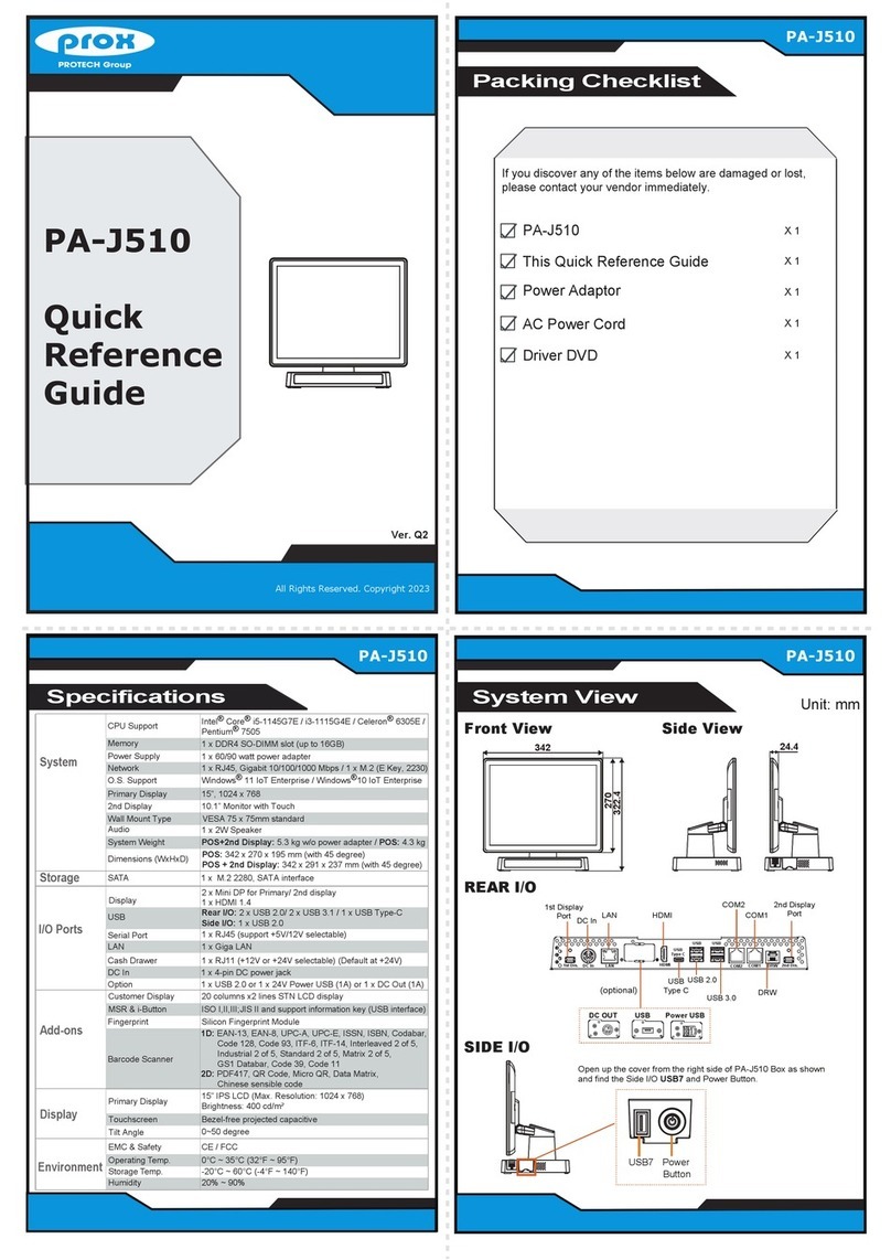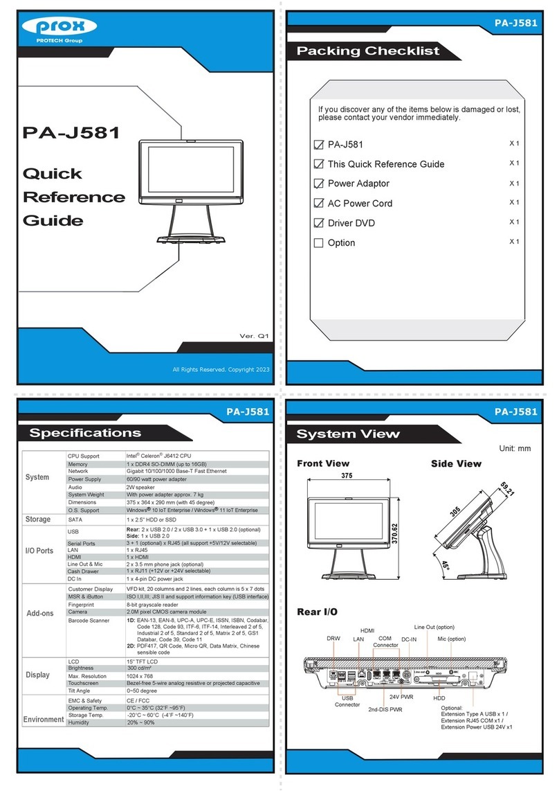
Easy Maintenance
PA-J580
High Performance 15” Fanless Slim POS Terminal
HDD Maintenance
All Right Reserved Copyright 2012
Step 4: Unassemble the HDD fixing
screw and remove the HDD
tray.
Step 1: Follow the red arrow to rotate
and remove I/O cover.
Step 2: Follow the red arrow to
remove the screw.
Step 3: Follow the red arrow
to pull out HDD Tray.
Jumper Setting
• Avoid putting heavy objects on top of the system.
• Don’t turn the system upside down. This may cause the hard drive to malfunction.
• Don’t allow foreign objects to fall into this product.
• If water or other liquid spills into this product, unplug the power cord immediately.
4. Good Care
• When the outside of the case is stained, remove the stain with a neutral washing agent with a cloth.
• Never use strong agents such as benzene and thinner to clean the system.
• If heavy stains are present, moisten a cloth with diluted neutral washing agent or with alcohol and then wipe thoroughly with a dry cloth.
• If dust has been accumulated on the outside, remove it by using a special made vacuum cleaner for computers.
• Don’t contact the surface of capacitive touch before entering your operation system, or capacitive touch may have problems for electrostatics interface.
• Don't exchange the M/B battery by yourself or serious damage may incur.
The following messages are reminders for safety on how to protect your systems from damages and extend a long life of the system.
1. Check the Cable Voltage
• Make sure the range of operating voltage between AC 100V ~ 240V. Otherwise, the system could be damaged.
2. Environmental Conditions
• Place your PA-J580 on a sturdy, level surface. Be sure to allow enough space to have easy access around the system.
• Avoid extremely hot or cold place to install the system.
• Avoid exposure to sunlight for a long period of time or in an airtight space.
• Avoid the system from any heating device or using it outdoors in a cold winter day.
• Bear in mind that the operating ambient temperature is from 0 ~ 35°C (32 ~ 95°F).
• Avoid moving the system rapidly from a hot place to a cold place and vice versa because condensation may come from inside of
the system.
• Place PA-J580 in strong vibration(s) may cause hard disk failure.
• Don’t place the system close to any radio active device in case of signal interference.
3. Handling
• If the system isn’t fully in DOS mode, adjust BIOS setting as the instruction:
Advanced Chipset Feature => Boot display => choose “LFP”.
CAUTION! Danger of explosion if battery is incorrectly replaced. Replace only with the same or equivalent type recommended by the manufacturer.
Dispose of used batteries according to the manufacturer’s instructions.
WARNING! Some internal parts of the system may have high electrical voltage. And therefore we strongly recommend that qualified engineers can
open and disassemble the system. The LCD and Touchscreen are easily breakable, please handle them with extra care.
All Rights Reserved. Copyright 2021
Arrangement of the Cable
Step 1: Press on the lower part of Stand
rear cover from both sides as shown:
Step 2: Press on the upper part of Stand
rear cover from both sides as below:
Step 3: Rotate to remove the cable cover,
and then wire the power adaptor cable
from the bottom into Stand.
The lower part of the
Stand opens slightly.
The Stand rear
cover is set apart
from the system.
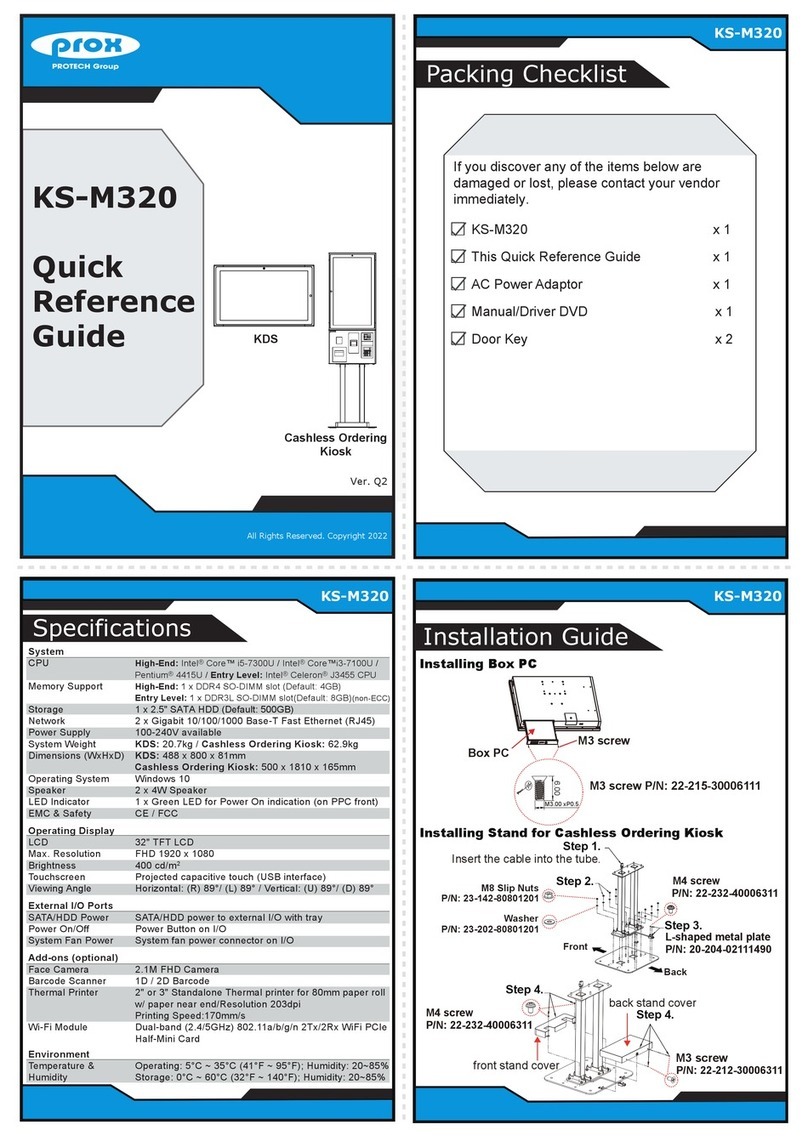
Place 60W power adaptor
outside of Stand.
Wire the power adaptor cable
from the bottom into Stand.
Step 4: Wire the power adaptor cable
through the wire hole of Stand
and plug the power adaptor
connector into DC-IN port to
complete.
Detail
Connect the
power adaptor
cable into DC In
port.
Wire the
power adaptor
cable through
the wire hole
on the rear
side of the
system.
Safety Precaution
(default)
JCOM2_1
JTOUCH1
COM2 Voltage
Selection
2 1
56
+12V
RI
2 1
56
2 1
56
+5V
Cash Drawer Voltage Selection
(default)
24V 12V
1
3
1
3
Dual Cash Drawer
Selection
1
(default)
DRW1
only
1
DRW1-1 &
DRW1-2
USB8 / On Board Touch
Selection
JP14
JP18
1
3
(default)
1
Normal
1
Clear RTC
Data
Clear RTC Data
Selection
(default)
1
Normal
1
Override
JP1 Flash Descriptor Override
Selection
M.2_E (Wi-Fi)
Selection
USB4 Selection
JP20
3
1
JP15
3
1
JP15
3
1
JP20
3
1
(default) (default)
LVDS VCC Selection
(default)
2 1
56
3.3V 5V
2 1
56
(default)
1
Normal
1
Clear CMOS
Data
Clear CMOS Data
Selection
DRW1
JP17
JHDD_PWR1
JP23
1
1
2
1
2
1
1
2
1
2
DC-IN
VGA
USB
3.0
USB
2.0
HDMI
LAN
JP_COM2
2
COM2
2
JP_COM3
JP3
JP_COM4
JCOM4_1
1
6
SATA1
JP13
JP19
JP9
JUSB6
JUSB7
JUSB910
2
JP16
JVOUT_24V
JVOUT_12V
1
1
1
1
1
1
JPS2
JP11
JP7
JP8
JI2C1
JINV1
M.2 E key
JP15
JP20
JUSB4
CPU_FAN1
1
JAUDIO1
JSPK1
1
JUSB8
JP18 JP14
11
1
1
1
1
1
CPU
JCMOS1
M.2 M key
1
JRTC1
JP1
1
2
1
1
1
JP5
JP6
JP4
1
1
1
6
JSYS_LED1
1
Super
I/O
JBAT1 JPWR_SW
JMCU
OSD_CTRL1
1
1
JP12
1
2
29
30
1 4
1 1
JLVDS1
1
1
1
1
1
1
1 7
1 1
1
274
75
1
274
75
M2_E
M2_M
5
1
COM4 Voltage Selection
6
2
RI
(default)
5 6
21
+12V
5 6
21
+5V
COM4 Port and iButton
Selection
(default)
COM4 I-BUTTON
1
3
1
3
Enable
5V
1
3
LVDS Backlight Control
Selection
3.3V
1
3
(default)
1
COM4
Disable
Enable COM4 Port
Selection
1
COM4
Enable
(default)
COM3 _1
1
6
LVDS Resolution Selection
(15” 1024x768)
2 1
56
JP7 JP8
2 1
56
(default) (default)
M/B: PB-5685
1
JP14JP18
1
3
JUSB8
(default)
JTOUCH1 1
3
1
3
