manuals.online logo
Brands
  1. Home
  2. •
  3. Brands
  4. •
  5. protech
  6. •
  7. Touch Terminal
  8. •
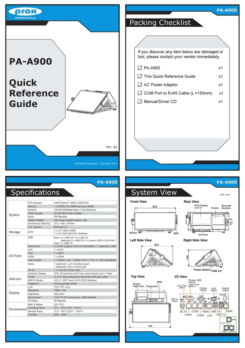
  9. protech prox PA-J581 User manual

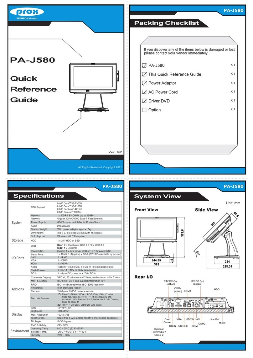
protech prox PA-J581 User manual

X 1
X 1
X 1
X 1
If you discover any of the items below is damaged or lost,
please contact your vendor immediately.
X 1
X 1
PA-J581
This Quick Reference Guide
AC Power Cord
Driver DVD
Option
Power Adaptor
All Right Reserved Copyright 2016
PA-6322
3
3
Front View
PA-63
PA-J581
Quick
Reference
Guide
All Right Reserved Copyright 2015
Ver. Q1
All Rights Reserved. Copyright 2023
Packing Checklist
PA-J581
PA-J581 PA-J581
System View
Side View
45°
59.21
305
Unit: mm
Rear I/O
Specifications
Customer Display
VFD kit, 20 columns and 2 lines, each column is 5 x 7 dots
Barcode Scanner
System
CPU Support
Storage
SATA 1 x 2.5" HDD or SSD
Memory 1 x DDR4 SO-DIMM (up to 16GB)
Network Gigabit 10/100/1000 Base-T Fast Ethernet
Audio 2W speaker
Power Supply 60/90 watt power adapter
System Weight With power adapter approx. 7 kg
Dimensions 375 x 364 x 290 mm (with 45 degree)
O.S. Support Windows®10 IoT Enterprise / Windows®11 IoT Enterprise
I/O Ports
Add-ons
MSR & iButton ISO I,II,III; JIS II and support information key (USB interface)
Fingerprint 8-bit grayscale reader
Display
USB Rear: 2 x USB 2.0 / 2 x USB 3.0 + 1 x USB 2.0 (optional)
Side: 1 x USB 2.0
Serial Ports 3 + 1 (optional) x RJ45 (all support +5V/12V selectable)
LAN 1 x RJ45
HDMI 1 x HDMI
Line Out & Mic 2 x 3.5 mm phone jack (optional)
Environment
EMC & Safety CE / FCC
-20°C ~ 60°C (-4˚F ~140˚F)
Humidity 20% ~ 90%
Intel®Celeron®J6412 CPU
Cash Drawer
DC In
1 x RJ11 (+12V or +24V selectable)
1 x 4-pin DC power jack
Camera 2.0M pixel CMOS camera module
1D: EAN-13, EAN-8, UPC-A, UPC-E, ISSN, ISBN, Codabar,
Code 128, Code 93, ITF-6, ITF-14, Interleaved 2 of 5,
Industrial 2 of 5, Standard 2 of 5, Matrix 2 of 5, GS1
Databar, Code 39, Code 11
2D: PDF417, QR Code, Micro QR, Data Matrix, Chinese
sensible code
LCD 15" TFT LCD
Max. Resolution 1024 x 768
Brightness 300 cd/m²
Touchscreen Bezel-free 5-wire analog resistive or projected capacitive
0~50 degreeTilt Angle
0°C ~ 35°C (32˚F ~95˚F)Operating Temp.
Storage Temp.
370.62
375
HDD
24V PWR
2nd-DIS PWR
DC-IN
Line Out (option)
Mic (option)
COM
Connector
HDMI
LAN
USB
Connector
DRW
Line-out HDD MIC
USB 3/4 USB 1/2
DRW
LAN HDMI
COM3 COM2 COM1 DC-IN
24V
PWR
2ND-DIS
PWR
Extension Type A USB x 1 /
Extension RJ45 COM x1 /
Extension Power USB 24V x1
Optional:
Easy Maintenance
All Right Reserved Copyright 2012
Jumper Setting
• Avoid putting heavy objects on top of the system.
• Don’t turn the system upside down. This may cause the hard drive to malfunction.
• Don’t allow foreign objects to fall into this product.
• If water or other liquid spills into this product, unplug the power cord immediately.
4. Good Care
• When the outside of the case is stained, remove the stain with a neutral washing agent with a cloth.
• Never use strong agents such as benzene and thinner to clean the system.
• If heavy stains are present, moisten a cloth with diluted neutral washing agent or with alcohol and
then wipe thoroughly with a dry cloth.
• If dust has been accumulated on the outside, remove it by using a special made vacuum cleaner for computers.
• Don’t contact the surface of capacitive touch before entering your operation system, or capacitive touch may have
problems for electrostatics interface.
• Don't exchange the M/B battery by yourself or serious damage may incur.
The following messages are reminders for safety on how to protect your systems from damages and to
extend a long life of the system.
1. Check the Cable Voltage
• Make sure the range of operating voltage between AC 100V ~ 240V. Otherwise, the system could
be damaged.
2. Environmental Conditions
• Place your PA-J581 on a sturdy, level surface. Be sure to allow enough space to have easy access
around the system.
• Avoid extremely hot or cold place to install the system.
• Avoid exposure to sunlight for a long period of time or in an airtight space.
• Avoid the system from any heating device or using it outdoors in a cold winter day.
• Bear in mind that the operating ambient temperature is from 0 ~ 35°C (32°F ~ 95°F).
• Avoid moving the system rapidly from a hot place to a cold place and vice versa because
condensation may come from inside of the system.
• Place PA-J581 in strong vibration(s) may cause hard disk failure.
• Don’t place the system close to any radio active device in case of signal interference.
3. Handling
• If the system isn’t fully in DOS mode, adjust BIOS setting as the instruction:
Advanced Chipset Feature => Boot display => choose “LFP”.
CAUTION! Danger of explosion if battery is incorrectly replaced. Replace only with the same or equivalent
type recommended by the manufacturer. Dispose of used batteries according to the manufacturer’s
instructions.
WARNING! Some internal parts of the system may have high electrical voltage. And therefore we strongly
recommend that qualified engineers can open and disassemble the system. The LCD and Touchscreen are
easily breakable, please handle them with extra care.
All Rights Reserved. Copyright 2023
PA-J581
15” Fanless Slim POS with Intel Celeron®J6412
HDD Maintenance
®
M/B: PB-J581 DC_IN1
HDMI1LAN1USB1USB2DRW1
29
2
1
56
2
1
56
2
1
56
COM2_2
COM3_2
COM2_1
COM3_1 COM1
JP_COM1
JP_COM2
JP_COM3
SATA1
1
JP7
1JP3
1
7
USB3_2
USB4_2
11
USB7
1
6
2
15
JP_USB4
1
5
62JP_USB3
M2_M1
M2_E1
JBAT1
1
1
USB5
VOUT_24
VOUT_12
1
1
1
VOUT_5
JPWRBTN1
SW3
USB5_2
1
2
1
56
JP_USB5
JVGA1
1
2
1516
USB6
5
1
5
2
1
JSYS_LED1
COM4
1
5
INV1
1
6
GPIO1
15
LVDS1
1
230
EDP1
130
CPU_FAN1
1
1
JP6
111
JP5 JP4JP2
4
1
SATA_PWR1
USB9
USB8
USB10
1
5
1
5
1
5
I2C1
1
4
JTOUCH1
1
SPK1
1
AUDIO1
1
2
9
DIMM1
1
JP1
6
2
15
JP_USB7
1
5
62
JP_USB8
12
57 58
67 68
75 74
1
2
22
23
32
74
75
M2
M1
1
JCMOS1
M3
CPU
JP2 LVDS BKLCTL PWM Voltage
Level Selection
1
5V
(default)
3.3V
11
JP4
Select
JP4 LVDS BKLCTL PWM Fix Voltage
Level Selection
1
5V
(default)
GND
11
JP2
Select
JP5 LVDS BKLCTL PWM Selection
1
7511
PWM
(default)
SOC
PWM
1
JP6 LVDS BKLTEN Voltage Level
Selection
1
(default)
1
3.3V 5V
JP1 LVDS VCC Voltage Selection
(default)
1
3.3V
1
5V
JP3 DRW1 Voltage Selection
(default)
1
24V
1
12V
JP_COM1, JP_COM2, JP_COM3
COM1, COM2, COM3 Port RI &
Voltage Selection
5V
1
2
2
65
12V
1 2
65
(default)
RI
1 2
65
JP_USB5
USB5 Port Selection
(default)
USB5
1 2
65
USB5_2
1 2
65
JP_USB3 USB3 Port Selection
51
2
6
USB3_2
(default)
USB3
51
2
6
JP_USB4 USB4 Port Selection
26
5
1
USB4
(default) USB4_2
26
5
1
JP_USB7 USB7 Port Selection
26
5
1
Touch
(default) USB7
26
5
1
JP_USB8 USB8 Port Selection
51
2
6
USB8
M2_M1
(default)
51
2
6
Clear CMOS Data Selection
1
(default)
Normal Clear CMOS
1
CAUTION!
Danger of explosion if
the battery is incorrectly
replaced. Replace only
with the same or
equivalent type
recommended by the
manufacturer. Dispose
of used batteries
according to the
manufacturer’s
instructions.
15
6 10
1 5
6 10
M.2 M key
M.2 E key
JP7 DRW1 Single / Dual Setting
Selection
1
DRW1-1 &
DRW1-2
(default)
1
DRW1 only
1
JRST1
Safety Precaution
1
4
5
8SW2
X 1
X 1
X 1
If you discover any item below was damaged or lost,
please contact your vendor immediately.
X 1
This Quick Reference Guide
AC Power Cord
Option
Power Adaptor
All Right Reserved Copyright 2016
3
Specifications
X 1
PA-J581
22
Front View
X 1
Driver DVD
PA-J581
Quick
Reference
Guide
All Right Reserved Copyright 2015
Ver. Q1
All Rights Reserved. Copyright 2023
Packing Checklist
PA-J581
3
PA-J581
Rear View
mUnit: m
3
PA-J581
System View
375
Rear I/O
Customer Display
VFD kit, 20 columns and 2 lines, each column is 5 x 7 dots
Barcode Scanner
System
CPU Support
Storage
SATA 1 x 2.5" HDD or SSD
Memory 1 x DDR4 SO-DIMM (up to 16GB)
Network Gigabit 10/100/1000 Base-T Fast Ethernet
Audio 2W speaker
Power Supply 60/90 watt power adapter
System Weight 3.8 kg
Dimensions 375 x 305 x 59.2 mm
O.S. Support Windows®10 IoT Enterprise / Windows®11 IoT Enterprise
I/O Ports
Add-ons
MSR & iButton ISO I,II,III; JIS II and support information key (USB interface)
Fingerprint 8-bit grayscale reader
Display
USB Rear: 2 x USB 2.0 / 2 x USB 3.0 + 1x USB 2.0 (optional)
Side: 1 x USB 2.0
Serial Ports 3 + 1 (optional) x RJ45 (all support +5V/12V selectable)
LAN 1 x RJ45
HDMI 1 x HDMI
Line Out & Mic 2 x 3.5 mm phone jack (optional)
Environment
EMC & Safety CE / FCC
-20°C ~ 60°C (-4˚F ~140˚F)
Humidity 20% ~ 90%
Intel®Celeron®J6412 CPU
Cash Drawer
DC In
1 x RJ11 (+12V or +24V selectable)
1 x 4-pin DC power jack
Camera 2.0M pixel CMOS camera module
1D: EAN-13, EAN-8, UPC-A, UPC-E, ISSN, ISBN, Codabar,
Code 128, Code 93, ITF-6, ITF-14, Interleaved 2 of 5,
Industrial 2 of 5, Standard 2 of 5, Matrix 2 of 5, GS1
Databar, Code 39, Code 11
2D: PDF417, QR Code, Micro QR, Data Matrix, Chinese
sensible code
LCD 15" TFT LCD
Max. Resolution 1024 x 768
Brightness 300 cd/m²
Touchscreen Bezel-free 5-wire analog resistive or projected capacitive
0~50 degreeTilt Angle
0°C ~ 35°C (32˚F ~95˚F)Operating Temp.
Storage Temp.
503
001
100
M4 screw hole (x4)
HDD
24V PWR
2nd-DIS PWR
DC-IN
Line Out (option)
Mic (option)
COM
Connector
HDMI
LAN
USB
Connector
DRW
Line-out HDD MIC
USB 3/4 USB 1/2
DRW
LAN HDMI
COM3 COM2 COM1 DC-IN
24V
PWR
2ND-DIS
PWR
Extension Type A USB x 1 /
Extension RJ45 COM x1 /
Extension Power USB 24V x1
Optional:
Easy Maintenance
All Right Reserved Copyright 2012
• Avoid putting heavy objects on top of the system.
• Don’t turn the system upside down. This may cause the hard drive to malfunction.
• Don’t allow foreign objects to fall into this product.
• If water or other liquid spills into this product, unplug the power cord immediately.
4. Good Care
• When the outside of the case is stained, remove the stain with a neutral washing agent with a cloth.
• Never use strong agents such as benzene and thinner to clean the system.
• If heavy stains are present, moisten a cloth with diluted neutral washing agent or with alcohol and
then wipe thoroughly with a dry cloth.
• If dust has been accumulated on the outside, remove it by using a special made vacuum cleaner for computers.
• Don’t contact the surface of capacitive touch before entering your operation system, or capacitive touch may have
problems for electrostatics interface.
• Don't exchange the M/B battery by yourself or serious damage may incur.
The following messages are reminders for safety on how to protect your systems from damages and to
extend a long life of the system.
1. Check the Cable Voltage
• Make sure the range of operating voltage between AC 100V ~ 240V. Otherwise, the system could
be damaged.
2. Environmental Conditions
• Place your PA-J581 on a sturdy, level surface. Be sure to allow enough space to have easy access
around the system.
• Avoid extremely hot or cold place to install the system.
• Avoid exposure to sunlight for a long period of time or in an airtight space.
• Avoid the system from any heating device or using it outdoors in a cold winter day.
• Bear in mind that the operating ambient temperature is from 0 ~ 35°C (32°F ~ 95°F).
• Avoid moving the system rapidly from a hot place to a cold place and vice versa because
condensation may come from inside of the system.
• Place PA-J581 in strong vibration(s) may cause hard disk failure.
• Don’t place the system close to any radio active device in case of signal interference.
3. Handling
• If the system isn’t fully in DOS mode, adjust BIOS setting as the instruction:
Advanced Chipset Feature => Boot display => choose “LFP”.
CAUTION! Danger of explosion if battery is incorrectly replaced. Replace only with the same or equivalent
type recommended by the manufacturer. Dispose of used batteries according to the manufacturer’s
instructions.
WARNING! Some internal parts of the system may have high electrical voltage. And therefore we strongly
recommend that qualified engineers can open and disassemble the system. The LCD and Touchscreen are
easily breakable, please handle them with extra care.
All Rights Reserved. Copyright 2023
PA-J581
15” Fanless Slim Panel PC with Intel Celeron®J6412
HDD Maintenance
Step 1: Rotate the cable cover.
Step 2: Unassemble the screw.
Step 3: Pull out HDD Tray.
Step 4: Unassemble the HDD fixing screw and take off the HDD tray.
®
Safety Precaution
Jumper Setting
M/B: PB-J581 DC_IN1
HDMI1LAN1USB1USB2DRW1
COM2_1
COM3_1 COM1
2
1
56
2
1
56
2
1
56
COM2_2
COM3_2
JP_COM1
JP_COM2
JP_COM3
SATA1
1
JP7
1JP3
1
7
USB3_2
USB4_2
11
USB7
1
6
2
15
JP_USB4
1
5
62JP_USB3
M2_M1
M2_E1
JBAT1
1
USB5
1
VOUT_24
VOUT_12
1
1
1
VOUT_5
JPWRBTN1
SW3
USB5_2
1
2
1
56
JP_USB5
JVGA1
1
2
1516
USB6
5
1
5
2
1
JSYS_LED1
COM4
1
5
INV1
1
6
GPIO1
15
LVDS1
1
2
29
30
EDP1
130
CPU_FAN1
1
1
JP6
111
JP5 JP4JP2
4
1
SATA_PWR1
USB9
USB8
USB10
1
5
1
5
1
5
I2C1
1
4
JTOUCH1
1
SPK1
1
AUDIO1
1
2
9
DIMM1
1
JP1
6
2
15
JP_USB7
1
5
62
JP_USB8
12
57 58
67 68
75 74
1
2
22
23
32
74
75
M2
M1
1
JCMOS1
M3
CPU
JP2 LVDS BKLCTL PWM Voltage
Level Selection
1
5V
(default)
3.3V
11
JP4
Select
JP4 LVDS BKLCTL PWM Fix Voltage
Level Selection
1
5V
(default)
GND
11
JP2
Select
JP5 LVDS BKLCTL PWM Selection
1
7511
PWM
(default)
SOC
PWM
1
JP6 LVDS BKLTEN Voltage Level
Selection
1
(default)
1
3.3V 5V
JP1 LVDS VCC Voltage Selection
(default)
1
3.3V
1
5V
JP7 DRW1 Single / Dual Setting
Selection
1
DRW1-1 &
DRW1-2
(default)
1
DRW1 only
JP3 DRW1 Voltage Selection
(default)
1
24V
1
12V
JP_COM1, JP_COM2, JP_COM3
COM1, COM2, COM3 Port RI &
Voltage Selection
5V
1
2
2
65
12V
1 2
65
(default)
RI
1 2
65
JP_USB5
USB5 Port Selection
(default)
USB5
1 2
65
USB5_2
1 2
65
JP_USB3 USB3 Port Selection
51
2
6
USB3_2
(default)
USB3
51
2
6
JP_USB4 USB4 Port Selection
26
5
1
USB4
(default) USB4_2
26
5
1
JP_USB7 USB7 Port Selection
26
5
1
Touch
(default) USB7
26
5
1
JP_USB8 USB8 Port Selection
51
2
6
USB8
M2_M1
(default)
51
2
6
Clear CMOS Data Selection
1
(default)
Normal Clear CMOS
1
CAUTION!
Danger of explosion if
the battery is incorrectly
replaced. Replace only
with the same or
equivalent type
recommended by the
manufacturer. Dispose
of used batteries
according to the
manufacturer’s
instructions.
15
6 10
1 5
6 10
M.2 M key
M.2 E key
1
JRST1
1
4
5
8SW2
Other protech Touch Terminal manuals

protech prox PA-J670 User manual

protech

protech prox PA-J670 User manual

protech POS-3150 Series User manual

protech

protech POS-3150 Series User manual

protech PA-3570 Series User manual

protech

protech PA-3570 Series User manual

protech PA-3310 User manual

protech

protech PA-3310 User manual

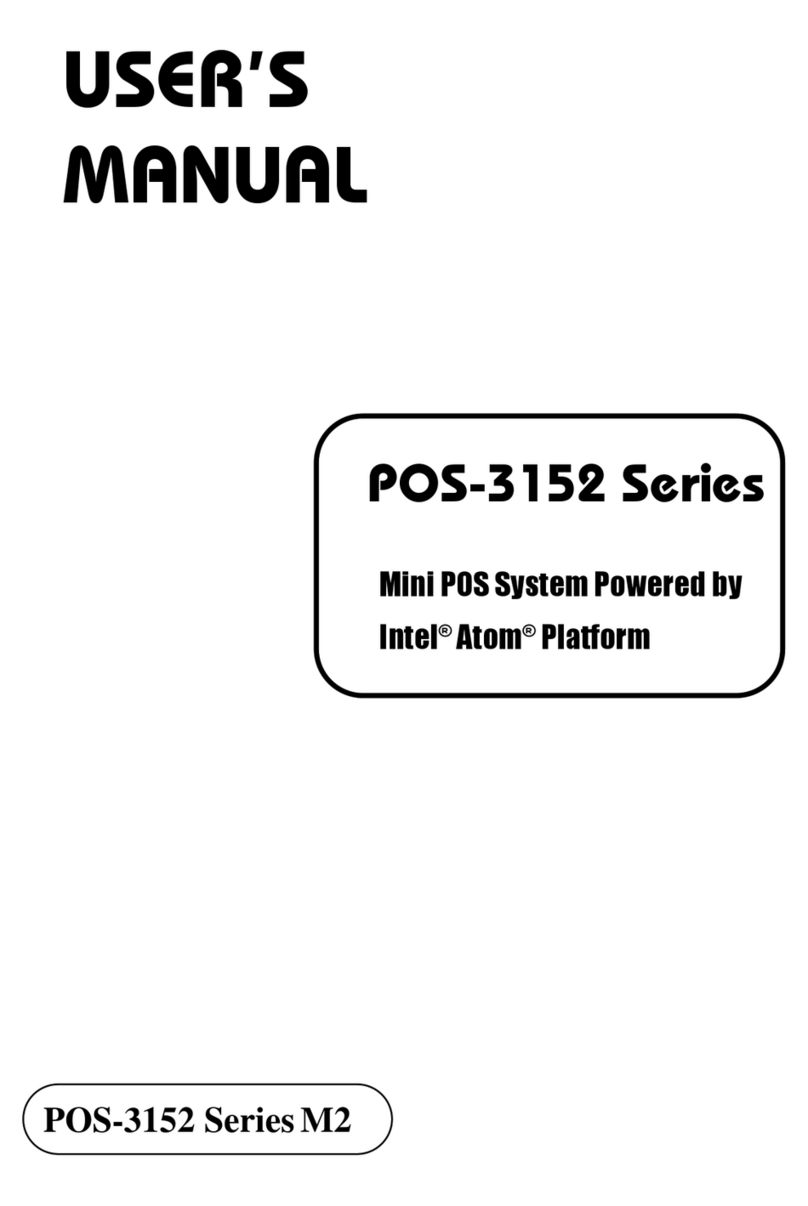
protech POS-3152 Series User manual

protech

protech POS-3152 Series User manual

protech PA-J501 User manual

protech

protech PA-J501 User manual

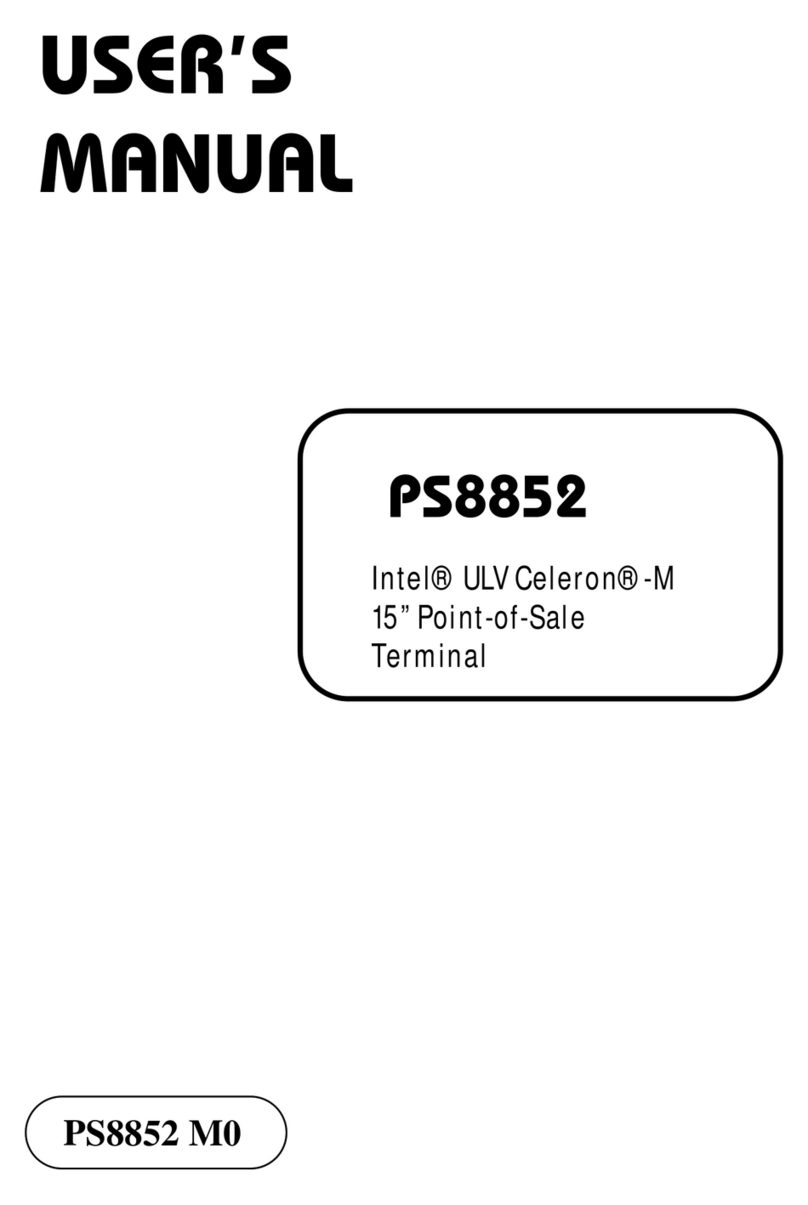
protech PS8852 User manual

protech

protech PS8852 User manual

protech PA-A901 User manual

protech

protech PA-A901 User manual

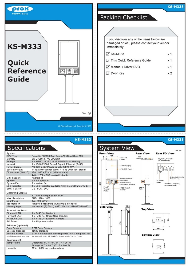
protech prox KS-M333 User manual

protech

protech prox KS-M333 User manual

protech prox PA-J600 User manual

protech

protech prox PA-J600 User manual

protech prox PA-J580 User manual

protech

protech prox PA-J580 User manual

protech PA-1922 User manual

protech

protech PA-1922 User manual

protech PA-3350 Series User manual

protech

protech PA-3350 Series User manual

protech PA-J581 Series User manual

protech

protech PA-J581 Series User manual

protech PA-6222 User manual

protech

protech PA-6222 User manual

protech PA-3320 User manual

protech

protech PA-3320 User manual

protech prox PA-6980 User manual

protech

protech prox PA-6980 User manual

protech PA-3622 User manual

protech

protech PA-3622 User manual

protech PA-2019 Series User manual

protech

protech PA-2019 Series User manual

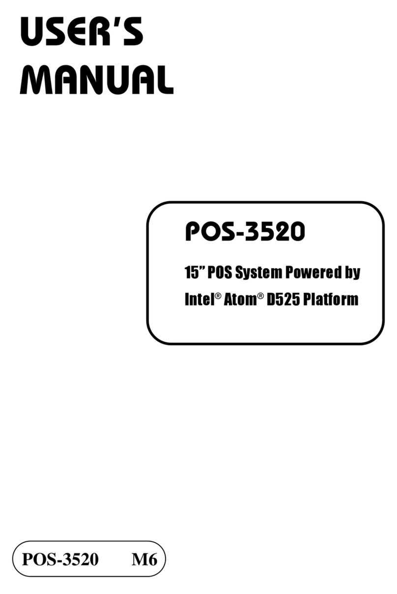
protech POS-3520 User manual

protech

protech POS-3520 User manual

protech PA-6225 User manual

protech

protech PA-6225 User manual

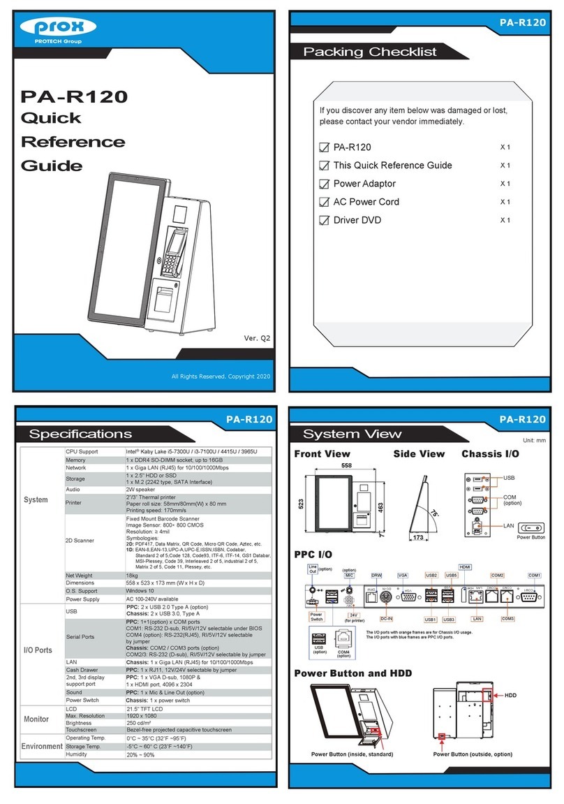
protech prox PA-R120 User manual

protech

protech prox PA-R120 User manual

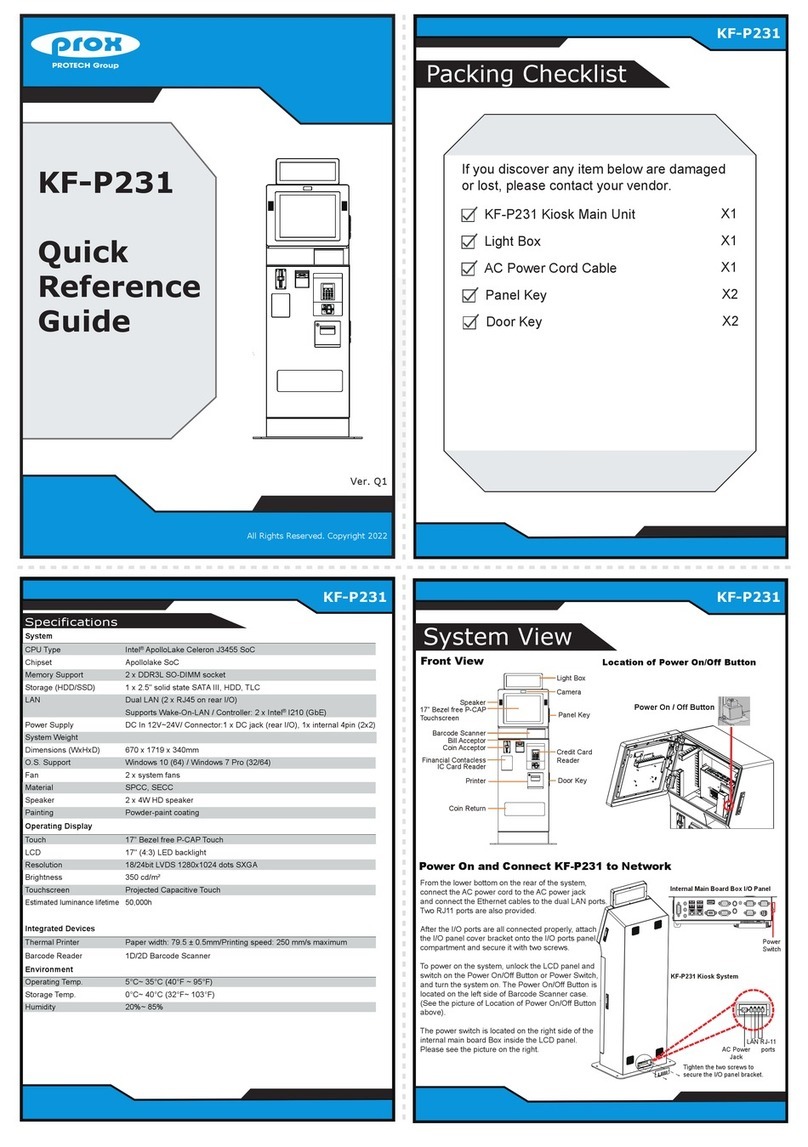
protech prox KF-P231 User manual

protech

protech prox KF-P231 User manual

protech KF-7130 User manual

protech

protech KF-7130 User manual

Popular Touch Terminal manuals by other brands

dasher d411 user manual

dasher

dasher d411 user manual

Touch Dynamic CS-200 user manual

Touch Dynamic

Touch Dynamic CS-200 user manual

Opticon H-13 quick start guide

Opticon

Opticon H-13 quick start guide

fSONA Sonabeam E Series installation manual

fSONA

fSONA Sonabeam E Series installation manual

Advantech TPC-1240 user manual

Advantech

Advantech TPC-1240 user manual

Philips/Magnavox MAT972A1 owner's manual

Philips/Magnavox

Philips/Magnavox MAT972A1 owner's manual

Casio DT-X100 Series Service manual

Casio

Casio DT-X100 Series Service manual

Wincor Nixdorf BEETLE /M-II plus user guide

Wincor Nixdorf

Wincor Nixdorf BEETLE /M-II plus user guide

Denso BHT-200 Supported equipment manual

Denso

Denso BHT-200 Supported equipment manual

Scientific Atlanta Explorer 4000DVB User's installation guide

Scientific Atlanta

Scientific Atlanta Explorer 4000DVB User's installation guide

First Data verifone vx 670 Quick setup guide

First Data

First Data verifone vx 670 Quick setup guide

Bodet KELIO PRIO V2 instructions

Bodet

Bodet KELIO PRIO V2 instructions

Huawei ETS2028 user guide

Huawei

Huawei ETS2028 user guide

POSIFLEX XT-3915 user manual

POSIFLEX

POSIFLEX XT-3915 user manual

Beckhoff KL3042 operating instructions

Beckhoff

Beckhoff KL3042 operating instructions

Siemens 8WH6000-0 0 Series operating instructions

Siemens

Siemens 8WH6000-0 0 Series operating instructions

Percon Falcon RF user manual

Percon

Percon Falcon RF user manual

Pro-face GP2500-TC41-24V installation guide

Pro-face

Pro-face GP2500-TC41-24V installation guide

manuals.online logo
manuals.online logoBrands
  • About & Mission
  • Contact us
  • Privacy Policy
  • Terms and Conditions

Copyright 2025 Manuals.Online. All Rights Reserved.