PSI PolyPen RP400 Guide

POLYPEN
RP400 & RP410
Manual and User Guide
Please read this manual before operating this product
PSI, spol. s r. o., Drásov 470, 664 24 Drásov, Czech Republic
FAX: +420 511 440 901, TEL: +420 511 440 011, www.psi.cz

© PSI (Photon Systems Instruments), spol. s r. o.
2
© PSI (Photon Systems Instruments), spol. s r. o. (hereinafter PSI), 2018
This document and its parts can be copied or provided to a third party only with the express permission
of PSI.
The contents of this manual have been verified to correspond to the specifications of the device.
However, deviations cannot be ruled out. Therefore, a complete correspondence between the manual
and the real device cannot be guaranteed. The information in this manual is regularly checked, and
corrections may be made in subsequent versions.
The visualizations shown in this manual are only illustrative.
This manual is an integral part of the purchase and delivery of equipment and its accessories and both
Parties must abide by it.

© PSI (Photon Systems Instruments), spol. s r. o.
3
1Table of Contents ................................................................................................................... 3
2Table of figures ...................................................................................................................... 4
3Technical Specification ........................................................................................................... 6
4General Information............................................................................................................... 8
5Components of the PolyPen device ....................................................................................... 10
6Description of the PolyPen device......................................................................................... 11
7Care and Maintenance.......................................................................................................... 13
8Operation Instructions.......................................................................................................... 14
8.1 Calibration...............................................................................................................................14
8.2 Measurement..........................................................................................................................15
8.3 Main menu ..............................................................................................................................16
9SPECTRAPEN SOFTWARE ...................................................................................................... 21
9.1 Driver Installation....................................................................................................................21
9.2 Software Installation...............................................................................................................22
9.3 SpectraPen Software Menu.....................................................................................................25
9.4 Data Transfer and Visualization..............................................................................................26
9.5 Online Control .........................................................................................................................31
9.6 Firmware Update ....................................................................................................................32
10 GPS module.......................................................................................................................... 34
10.1 GPS / PolyPen Operation.........................................................................................................34
11 How can I program my own index in the PolyPen RP 400....................................................... 36
11.1 Function description................................................................................................................37
12 Statement of limited warranty.............................................................................................. 39
1TABLE OF CONTENTS

© PSI (Photon Systems Instruments), spol. s r. o.
4
Fig. 1 PolyPen device .................................................................................................................... 11
Fig. 2 Schematic drawing of the principle of reflectance measurement in PolyPen RP400 & RP410.. 12
Fig. 3 Reflectance standard Spectralon® ........................................................................................ 14
Fig. 4 Calibration of device............................................................................................................ 15
Fig. 5 Getting reflectance values ................................................................................................... 15
Fig. 6 Indexes table....................................................................................................................... 16
Fig. 7 Calibration of device............................................................................................................ 17
Fig. 8 Menu Data .......................................................................................................................... 17
Fig. 9 Settings → Indexes .............................................................................................................. 18
Fig. 10 Index selection .................................................................................................................. 18
Fig. 11 Graph features .................................................................................................................. 19
Fig. 12 Time setting...................................................................................................................... 19
Fig. 13 Display intensity and time-out settings............................................................................... 20
Fig. 14 Number of reading scans and GPS module function ............................................................ 20
Fig. 15 Device registration step ..................................................................................................... 23
Fig. 16 PolyPen connection with PC............................................................................................... 23
Fig. 17 PolyPen device connection in SpectraPen software ............................................................ 24
Fig. 18 Failed PolyPen connection ................................................................................................. 24
Fig. 19 Scope spectra .................................................................................................................... 26
Fig. 20 Absorbance ....................................................................................................................... 27
Fig. 21 Transmittance ................................................................................................................... 27
Fig. 22 Marker feature .................................................................................................................. 28
Fig. 23 Zoom feature..................................................................................................................... 29
Fig. 24 Transmittance –reflectance indexes .................................................................................. 29
Fig. 25 Export menu...................................................................................................................... 30
Fig. 26 Export –Computed data selection and choosing of exported values.................................... 30
Fig. 27 Online Control ................................................................................................................... 31
2TABLE OF FIGURES

© PSI (Photon Systems Instruments), spol. s r. o.
5
Fig. 28 Settings of online control ................................................................................................... 32
Fig. 29 Switching on the GPS module............................................................................................. 34
Fig. 30 GPS icon ............................................................................................................................ 34
Fig. 31 Exported data with the GPS mark....................................................................................... 35
Fig. 32 Formulas configuration file –adding new index.................................................................. 36
Fig. 33 Downloaded data with new index...................................................................................... 37

© PSI (Photon Systems Instruments), spol. s r. o.
6
Spectral response range:
380 nm –790 nm (UVIS), 640 nm –1050 nm (NIR)
Spectral response half width:
8 nm
Light source:
Xenon incandescent lamp 380 - 1050 nm
Spectral straylight*:
-30dB
Optical aperture diameter:
5 nm
Scanning Speed
About 100 ms
System data:
16 bit AD conversion
Dynamic range:
High gain: 1:4,300; low gain: 1:13,000
Memory Capacity:
Up to 32Mb
Internal Data Logging:
Up to 4000 measurements
Display:
240 × 320 pixel; 65,535 colors; touch screen
Battery:
Li-ion; rechargeable via USB port of a PC
Battery Life:
48 hours typical with full operation
Communication:
USB
SpectraPen Software:
Windows XP, or higher compatible**
Size:
15 ×7.5 ×4 cm
Weight:
300 g, 10.6 oz
Case:
Splash-proof
Operating Conditions:
Temperature: 0 to 55 ºC; 32 to 130 ºF Relative humidity: 0 to 95 % (non-condensing)
3TECHNICAL SPECIFICATION

© PSI (Photon Systems Instruments), spol. s r. o.
7
Storage Conditions:
Temperature: -10 to +60 ºC; 14 to 140 ºF Relative humidity: 0 to 95 % (non-condensing)
Warranty:
1 year parts and labor (see the last page of this Operation Manual for precise warranty conditions)
* When monochromatic light of Λ = 550 nm or Λ = 850 nm is input, spectral stray light is defined as the ratio of
the count measured at the input wavelength, to the count measured at a wavelength 40 nm longer or shorter
than the input wavelength
** Windows is a registered trademark of Microsoft Corporation.

© PSI (Photon Systems Instruments), spol. s r. o.
8
PolyPen RP400 & RP410 (in further text - PolyPen) is a portable, handheld spectro-radiometer. The PolyPen
features a complete system primarily designed for a measurement of spectral reflectance of leaves or other
planar samples. However, the device can be easily implemented also for simple measurement of spectra of any
external light sources e.g. sun, lamps in growth chambers, etc. The system is convenient for both, indoor as well
as field applications owing to an inbuilt GPS module.
The PolyPen is a self-contained instrument powered by a Lithium-ion battery which is rechargeable via a PC and
a USB cable. However, it does not require a PC for operation. Reflectance spectra and calculated reflectance
indices are instantly displayed on the PolyPen touch screen and all stored in the device internal memory.
Integrated USB communication allows data transfer to a PC at a later time. Measured spectra and calculated
indices are stored as full spectrum and individual values (respectively).
The PolyPen device integrates an internal light source (Xenon incandescent lamp) with radiation range 380 –
1050 nm. Two versions of detectors are available for UV/VIS and NIR spectral regions.
VERSIONS
POLYPEN RP 400 UVIS
Spectral response range: 380 to 780 nm.
POLYPEN RP 400 NIR
Spectral response range: 640 to 1050 nm.
The PolyPen device incorporates formulas of commonly used reflectance indices (e.g. NDVI, NDGI, PRI etc.)
directly in its software and displays values of the selected indices instantly. The PolyPen allow calculation of the
following pre-defined parameters:
Transmittance –calculated using the following formula
T= I/I0
Where: I0is reference light intensity
Iis measured light intensity
Absorbance –calculated data using the following formula
A= log(I0/I)
Where: I0is reference light intensity
Iis measured light intensity
List of vegetation indices are automatically calculated for the measured sample based on the reflectance
spectra.
LIST OF CALCULATED VEGETATION INDEXES:
Normalized Difference Vegetation Index (NDVI)
Reference: Rouse et al. (1974)
Equation: NDVI = (RNIR -RRED ) / (RNIR +RRED )
Simple Ratio Index (SR)
Reference: Jordan (1969); Rouse et al. (1974)
Equation: SR = RNIR / RRED
Modified Chlorophyll Absorption in Reflectance Index (MCARI1)
Reference: Haboudane et al. (2004)
Equation: MCARI1 = 1.2 * [2.5 * (R790- R670) - 1.3 * (R790- R550)]
4GENERAL INFORMATION

© PSI (Photon Systems Instruments), spol. s r. o.
9
Optimized Soil-Adjusted Vegetation Index (OSAVI)
Reference: Rondeaux et al. (1996) )
Equation: OSAVI = (1 + 0.16) * (R790- R670) / (R790- R670 + 0.16)
Greenness Index (G)
Equation: G= R554 / R677
Modified Chlorophyll Absorption in Reflectance Index (MCARI)
Reference: Daughtry et al. (2000)
Equation: MCARI = [(R700- R670) - 0.2 * (R700- R550)] * (R700/ R670)
Transformed CAR Index (TCARI)
Reference: Haboudane et al. (2002)
Equation: TCARI = 3 * [(R700- R670) - 0.2 * (R700- R550) * (R700/ R670)]
Triangular Vegetation Index (TVI)
Reference:Broge and Leblanc (2000)
Equation: TVI = 0.5 * [120 * (R750- R550) - 200 * (R670- R550)]
Zarco-Tejada & Miller Index (ZMI)
Reference: Zarco-Tejada et al. (2001)
Equation: ZMI = R750 / R710
Simple Ratio Pigment Index (SRPI)
Reference: Peñuelas et al. (1995)
Equation: SRPI = R430 / R680
Normalized Phaeophytinization Index (NPQI)
Reference: Barnes et al. (1992)
Equation: NPQI = (R415- R435) / (R415+ R435)
Photochemical Reflectance Index (PRI)
Reference: Gamon et al. (1992)
Equation: PRI = (R531- R570) / (R531+ R570)
Normalized Pigment Chlorophyll Index (NPCI)
Reference: Peñuelas et al. (1994)
Equation: NPCI = (R680- R430) / (R680+ R430)
Carter Indexes
Reference: Carter (1994), Carter et al. (1996)
Equation: Ctr1 = R695 / R420; Ctr2 = R695 / R760
Lichtenthaler Indexes
Reference: Lichtenthaler et al. (1996)
Equation: Lic1 = (R790 - R680) / (R790 + R680); Lic2 = R440 / R690
Structure Intensive Pigment Index (SIPI)
Reference: Peñuelas et al. (1995)
Equation: SIPI = (R790- R450) / (R790+ R650)
Gitelson and Merzlyak Indexes
Reference: Gitelson&Merzlyak (1997)
Equation: GM1 = R750/ R550; GM2 = R750/ R700)
Anthocyanin Reflectance Indexes
Reference: Gitelson et al. (2001)
Equation: ARI1 = 1/R550 –1/R700; ARI2 = R800 * (1/R550 –1/R700)
Carotenoid Reflectance Indexes
Reference: Gitelson et al. (2002)
Equation: CRI1 = 1/R510 –1/R550; CRI2 = 1/R510 –1/R700
Note: Besides the pre-defined vegetation indices, the user has the possibility to define own formula based on
specific wavelengths identified. The calculation of the designed formula can be specified in the Config file of the
device and subsequently automatically calculated and displayed among routinely calculated indices (please refer
to page 36 for explanation).

© PSI (Photon Systems Instruments), spol. s r. o.
10
Carefully unpack the carton. You should have received the following items, as described in table below:
1. PolyPen RP400
2. Reflectance standard (Spectralon®)
3. Stylus
4. Carrying Case
5. Textile Strap for Comfortable Wearing
6. This Operation Manual (PDF file on a USB flash disc)
7. USB flash disc with SpectraPen software and driver
8. USB Communication Module
9. Other Accessories or Optional Features (according to your specific order)
Note: If any item is missing, please, contact the manufacturer. Please check the carton for any visible external
damage. If you find any damage, notify the carrier and PSI immediately. The carton and all packing materials
should be retained for inspection by the carrier or insurer. For customer support, please contact us at:
5COMPONENTS OF THE POLYPEN DEVICE

© PSI (Photon Systems Instruments), spol. s r. o.
11
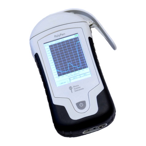
PolyPen is a compact, durable and lightweight device operated by single Turn ON/OFF button and touch screen
(Fig. 1). PolyPen device is optimized for photo-biological applications and easy rapid measurements inside of the
controlled environment as well as outside in the field. It features an innovative user interface with an integral
computer, a full color touch screen display and an in-built light source. The PolyPen is equipped with a non-
destructive leaf-clip sample holder. For data collection and analysis, a comprehensive software package is
provided. PolyPen RP400 can be connected to PC for further data collection and analysis via USB connector.
An integral part of the PolyPen is broad-spectrum internal light source (Xenon incandescent lamp) with radiation
range 380 –1050 nm. The light beam strikes the sample under the fixed angle of incidence 35°(Fig. 2). The
PolyPen system is optimized particularly for a measurement of planar samples such as leaves. Please note the
variability and reproducibility of the measurement performed with more structured samples like conifer needles
can be affected simply by the geometry of the measurement.
Fig. 1 PolyPen device
LEAF CLIP
PolyPen is equipped with a non-destructive leaf-clip sample holder.
COLOUR LCD DISPLAY
PolyPen is operated via a touch screen by using a supplied stylus. The software operation instructions are
available on page 25.
Please note: No sharp objects should be used for touch screen operation. It is recommended to use the provided
stylus.
USB CONNECTOR
USB connector is used for operation of the PolyPen device directly from PC via the SpectraPen software and for
re-charging the device batteries. Please note that PolyPen device is automatically re-charged when connected to
the PC via the USB connector.
POWER BUTTON
Power button is the main Switch ON/OFF button.
6DESCRIPTION OF THE POLYPEN DEVICE

© PSI (Photon Systems Instruments), spol. s r. o.
12
Fig. 2 Schematic drawing of the principle of reflectance measurement in PolyPen RP400 & RP410. The light
source is oriented in 35°to the normal line intersecting the detector.

© PSI (Photon Systems Instruments), spol. s r. o.
13
Never submerge the device in water!
The device should not come in contact with any organic solvents, strong acids or bases.
Battery life is approximately 48 hours when the PolyPen is operated continuously.
Use the provided stylus for the touch-screen operation. Avoid usage of any sharp objects.
7CARE AND MAINTENANCE

© PSI (Photon Systems Instruments), spol. s r. o.
14
This chapter provides instructions on an initial set-up operation of the PolyPen RP400 device as well as detailed,
step-by-step description of a measurement procedure.
To switch the PolyPen ON, press the POWER BUTTON until the device logo shows up. Follow next steps to
perform the measurements. In case the device battery is not charged, connect the PolyPen with USB cable via
USB port to the PC and charge the batteries.
8.1 CALIBRATION
Calibration pf the PolyPen device MUST be done prior measurement after the turning on of the device. The
calibration of the white reflectance standard is an indispensable part of a correct calculation of reflectance
spectrum. The calibration scan must be performed always after the device switched ON or it should be
periodically repeated upon certain time period of the device operation. The calibration is not needed for
a simple measurement of spectra of external light sources.
For calibration of device use special reflectance standard Spectralon®* (Fig. 3). Calibration is required every time
the device is turned ON.
* Spectralon®is a registered trademark of Labsphere.
Please follow the instructions below for device calibration:
In the main window go to > Calibrate >press OK (Fig. 4).
Use the Spectralon®standard (Fig. 3) for white calibration. For dark calibration close the leaf clip only
(“standard” is on bottom part of the leafclip).
Close leaf clip.
Press OK and wait until the calibration step is completed.
Calibration is automatically stored into the device memory.
After the calibration step is performed, Main window icon Calibrate (Fig. 4) will change into Get
reflectance (Fig. 5). Get Reflectance –shows up after successful calibration, measures and stores
reflectance spectrum.
Spectralon®standard is spectrally flat over UV-VIS-NIR spectrum and optically flat to +/- 1 % over the
photopic region of the spectrum.
The device is now ready to measure other samples.
Fig. 3 Reflectance standard Spectralon®
8OPERATION INSTRUCTIONS

© PSI (Photon Systems Instruments), spol. s r. o.
15
Fig. 4 Calibration of device
Fig. 5 Getting reflectance values
8.2 MEASUREMENT
PolyPen RP400 and RP410 are a complete systems for a measurement of reflectance spectra of planar samples
such as leaves.
Besides the whole spectrum information, the PolyPen incorporates pre-defined formulas for calculation of
commonly used plant reflectance indices (e.g. NDVI, NDGI, PRI, Greenness Index, etc.) directly in its software.
The measured data are instantly displayed in graphs or data sheets on the device screen display. They are also
stored in the device memory for later re-collection or transfer to a PC.
Please follow these instructions to perform a measurement:
Insert a leaf sample into the leaf clip. The leaf clip is important for the sample stabilization.
In the main window select > Get Reflectance > press OK (Fig. 5).

© PSI (Photon Systems Instruments), spol. s r. o.
16
Press OK and wait until the measurement is completed.
Measurements are automatically stored into the device memory and displayed on the screen.
Currently displayed graph represents transmittance data. Displayed graph would be switched to
absorbance data in Options menu (more information in chapter 8.3).
oTransmittance: the transmittance mode corresponds with reflectance in case of PolyPen
device. The measured spectral data are normalized to the white calibration standard by the
linear calculation: T= I/I0, where Imeans the signal measured from the sample and I0is the
ideal reflectance signal from the standard.
oAbsorbance: The measured data are normalized to the white calibration standard as the
logarithmic ratio: A= log(I0/I). This visualization mode does not have a special meaning in case
of PolyPen device, as this function is important for the trans-illumination geometry
measurement in PolyPen-Aqua.
INDICES TABLE
The table displays a group of selected indices calculated for actual measured data (Fig. 6). To define the
indices of interest, go to Options > Settings > Indexes. You can select two indices that are currently
displayed. However all indices are calculated and stored in the device memory. Entire list of the indices
can be displayed after a data download to PC. The software also allows a calculation of custom indices
defined by user (please refer to page 36).
Fig. 6 Indexes table
8.3 MAIN MENU
In this chapter the settings of the optimal device parameters and features of displayed data are described.
DEVICE
Calibrate –calibration can be run any time by pressing Device > Calibrate after inserting appropriate standard in
the leaf clip. (Fig. 7).

© PSI (Photon Systems Instruments), spol. s r. o.
17
Fig. 7 Calibration of device
DATA
Browse –displays data browse dialog box. The user can browse the list of stored data, select the set of
data files and view the light spectra in Transmittance or Absorbance mode (Options > Settings >
> Graph). Color classification of each data file helps user to discriminate between individual modes. Up
to 3 sets of collected data can be displayed at once by checking off the last column in the data table.
Erase –erase function is used to delete the internal data memory.
Memory info –displays info on amount of used internal memory of the PolyPen RP400 or RP410
devices.
Fig. 8 Menu Data
OPTIONS
Settings –function is used to set various variables for the light measurements and for the
device settings (Fig. 9).
oIndexes - Select indexes to be calculated and displayed on the main screen (Fig. 10).

© PSI (Photon Systems Instruments), spol. s r. o.
18
Fig. 9 Settings → Indexes
Fig. 10 Index selection
oGraph –displays options for setting the wavelength range and graph features (Fig. 11).
Zoom enable –enables the zoom feature. Select an area (in the right-down
direction) of the displayed graph, which you want to zoom in. Reverse these steps if
you want to return to the original graph size.
Marker enable –enables to display exact numeric value for the point selected
in the Scope graph window. Exact wavelength and light irradiance are displayed for the
point, which is selected by touching on the display. In top right corner of the LCD
display the exact value of wavelength in nm is shown for the user selected position in
spectra. In addition, light irradiance for the given nm is shown.
Smoothing –enables noise reduction of the graphical display (only on display)
by smoothing the noise in the spectrum at the expense of spectral resolution. Data are
not affected (calculated as moving average).
Absorbance –switches to absorbance mode of spectrum visualization, the
raw spectral data are calculated according to the formula (A = log(I0/I).
Wavelength range –defines the range of wavelengths considered for light
scope and light meter measurements. Desired wavelength range can be adjusted by
selecting the wavelength and by using the arrows up and down.

© PSI (Photon Systems Instruments), spol. s r. o.
19
Fig. 11 Graph features
oTime - Set the actual time and date (all data files are stored by time and date signature).To
change time, touch on one of the values and adjust it using the arrows (Fig. 12).
Fig. 12 Time setting
oLCD –is used to adjust LCD display control settings (Fig. 13).
Backlight intensity –move slider to adjust backlight intensity.
Backlight time-out –move slider to adjust backlight time-out (time of
inactivity required before backlight will dim out to save battery life).

© PSI (Photon Systems Instruments), spol. s r. o.
20
Fig. 13 Display intensity and time-out settings
oDevice
Average –Average function is used for adjusting the number of scans for each
reading. Averaging of more scans results in a higher signal-to-noise ratio but
increases the time required for each reading that appears on the screen.
Move slider to set the number of measurement to be acquired for averaged
values (Fig. 14). Data are affected.
GPS –enables the GPS module. The GPS coordinates cannot be displayed at
the device display, but they are exported together with data and visualized in
SpectraPen software.
Fig. 14 Number of reading scans and GPS module function
Other manuals for PolyPen RP400
1
This manual suits for next models
1
Table of contents
Other PSI Measuring Instrument manuals
Popular Measuring Instrument manuals by other brands

Pentax
Pentax TH-10 Instruction book

Crossbow Technology
Crossbow Technology AHRS400 Series user manual
KRAL
KRAL OMG Series operating instructions
Hanna Instruments
Hanna Instruments HI 93700 instruction manual
Apogee Instruments
Apogee Instruments SI-121-SS owner's manual
Tektronix
Tektronix VM700T instructions


