QDI LegenX 8 User manual

Declarationofconformity
QUANTUMDESIGNS(HK)LTD.
5/FSomersetHouse,TaiKooPlace 979 KingsRoad,
QuarryBay,HongKong
declaresthatthe product
Motherboard
LegenX8
isinconformitywith
(referencetothespecificationunderwhichconformityisdeclaredin
accordancewith89/336 EEC-EMCDirective)
þEN55022 Limitsand methodsofmeasurementsofradiodisturbance
characteristics ofinformationtechnologyequipment
þEN50081-1GenericemissionstandardPart1:
Residential,commercialandlightindustry
þEN50082-1GenericimmunitystandardPart1:
Residential,commercialandlightindustry
EuropeanRepresentative:
QDICOMPUTER(UK)LTDQDICOMPUTER(SCANDINAVIA)A/S
QDISYSTEMHANDELGMBHQDICOMPUTER(NETHERLANDS)B.V.
QDICOMPUTER(FRANCE)SARLQDICOMPUTERHANDELSGMBH
QDICOMPUTER(ESPANA)S.A.QDICOMPUTER(SWEDEN)AB
Signature:Place/Date:HONGKONG/1998
PrintedName:AndersCheung Position/Title:President

Declaration ofconformity
TradeName:QDIComputer(U.S.A.)Inc.
ModelName:LegenX8
ResponsibleParty:QDIComputer(U.S.A.)Inc.
Address:41456 ChristyStreet
Fremont,CA94538
Telephone:(510)668-4933
Facsimile:(510)668-4966
EquipmentClassification:FCC Class BSubassembly
TypeofProduct:Motherboard
Manufacturer:QuantumDesigns(HK)Inc.
Address:5/F,SomersetHouse,TaiKoo Place
979 KingsRoad,QuarryBay,HONG
KONG
SupplementaryInformation:
Thisdevice complieswithPart15oftheFCCRules.Operationissubjectto
thefollowing twoconditions:(1)thisdevicemaynotcauseharmfulinterfer-
ence,and (2)thisdevicemustacceptanyinterference received,including
interferencethatmaycauseundesiredoperation.
Signature:Date:1998

1.Introduction ............................................................... 1
Overview.......................................................................................... 1
KeyFeatures..................................................................................... 1
2.InstallationInstructions............................................. 5
ExternalConnectors.............................................................. 5
PS/2Keyboard&PS/2MouseConnector............................................ 5
USB1&USB2...................................................................................... 5
ParallelPortConnectorand SerialPortConnector................................ 5
Line-injack,Microphone-injack,Speaker-outjackandMIDI/Joystick
connector.......................................................................................... 6
ATXPowerSupplyConnector&PowerSwitch................................... 6
HardDiskLEDConnector(HD_LED).................................................... 6
ResetSwitch(RESET)....................................................................... 6
SpeakerConnector(SPEAKER).......................................................... 7
PowerLEDConnector(PWR_LED)...................................................... 7
Key_Lock Connector(KEY_L)............................................................ 7
ACPILEDConnector(GREEN_LED).................................................... 7
HardwareGreenConnector(SLEEP)................................................... 7
InfraredHeader(IrDA)........................................................................ 8
FanConnector(CPUFAN&CHSFAN).................................................... 8
Wake-UpOnLAN(WOL).................................................................... 8
Wake-UpOnInternalModem(WOM)................................................... 9
DigitalAudioConnector(JP6).............................................................. 9
HardwareVolumeControl(S1,S2)..................................................... 9
ExpansionSlots&I/OPortsdescription............................................. 10
JumperSettings.......................................................................... 10
ClearCMOS..................................................................................... 10
Enable/Disableon-boardaudio(JP8).................................................. 10
CONTENTS
I

Enablekeyboardpasswordpower-onfunction(JKB).......................... 11
FlashBIOSjumper(JAV)(manufacturing option).................................... 11
MemoryConfiguration.............................................................. 12
3.BIOSDescription.............................................................. 13
UtilitySupport........................................................................... 13
FLASH.EXE..........................................................................................13
AWARD BIOSDescription........................................................ 15
EnteringSetup .....................................................................................15
LoadSetup Defaults.......................................................................... 15
StandardCMOSSetup ....................................................................... 15
BIOSFeaturesSetup ........................................................................ 18
ChipsetFeaturesSetup...................................................................... 20
PowerManagementSetup ................................................................. 22
PNP/PCIConfigurationSetup............................................................... 25
IntegratedPeripherals........................................................................ 27
SystemMonitor.................................................................................. 29
Supervisor/UserPassword................................................................ 30
IDEHDD AutoDetection...................................................................... 31
BootwithBIOSdefaults..................................................................... 32
4.YAMAHAAudioDescription................................................. 33
Features..............................................................................................33
YAMAHASoftwareInstallation.............................................................33
InstallationofWindows95/98 Driver.....................................................33
InstallationofDos/Windows3.1XDriver...............................................35
InstallationofWindowsNT4.0Driver...................................................35
AppendixAQDIMotherboardUtilityCD-ROM...................... 37
AppendixBBootLogo ........................................................ 39
CONTENTS
II

ManualforLegenX8
Chapter1
Introduction
Chapter1
Introduction
Overview
TheLegenX8greenmotherboardutilizesthe Intel®440LXAGPsetandprovidesahighly
integratedsolutionforfullycompatible,highperformancePC/microATXplatform.Itprovides
66MHzsystembussupportforallIntelCeleronTMPPGA370 processors.Both66MHz
SDRAMandEDODRAMsaresupported.Italsoprovidesadvanced featuressuchaswake-
up onLAN,wake-up oninternal/externalmodemand keyboardpasswordpower-onfunc-
tion.ManageEasy,oursystemmanagementapplication issupplied toenableremotemonitor-
ingandconfiguration ofthe system.Thegreenfunction isincompliancewiththeACPI
specification.
Key Features
Formfactor
l MicroATXformfactorof244mm x200mm.
Microprocessor
lSupportsIntelCeleronTMPPGA370processorsat300A/333/366/400/433/466MHz.
l Supports66MHzhostbusspeed.
l CPUcoresupplyvoltageadjustablefrom1.3Vto2.05Vthrough on-boardswitching
voltage regulatorwithVID(VoltageID).
Chipset
l Intel®440LXAGPset: 82443LX,82371EB(PIIX4E)
Systemmemory
l Providestwo168 pin3.3VunbufferedDIMM sockets.
lSupportsboth66MHzSDRAMsandEDODRAMs.
lMinimummemorysizeis8MB,maximummemorysizeis512MB.
l SDRAM64 bitdatainterfacewithECC support.
On-boardIDE
l SupportstwoPCIPIO and BusMasterIDEports.
l
TwofastIDEinterfacessupportingfourIDEdevicesincluding IDEharddisksand
CD -ROMdrives.
l
Supportsup toPIOMode4timing.
l
Supports“UltraDMA/33”SynchronousDMAmodetransferring up to33 Mbytes/sec.
l
Integrated16x32bitbufferforIDEPCIBurstTransfers.
1
Chapter1

ManualforLegenX8
On-boardI/O
l
UseWinbondW83977EFsuperI/Ochip.
l
Onefloppyportsupporting up totwo3.5’’or5.25”floppydriveswith
360K/720K/1.2M/1.44M/2.88Mformat.
l
Twohighspeed 16550compatibleUARTs(COM1/COM2/COM3/COM4selective)
with16-bytesend/receiveFIFOs.
l
OneenabledparallelportattheI/Oaddress 378H/278H/3BCH withadditional
bi-directionI/Ocapabilityandmulti-modeasSPP/EPP/ECP(IEEE1284compliant).
l
Circuitprotectionprovided,preventing damagetotheparallelportwhena
connectedprinterispoweredup oroperatesatahighervoltage.
l
SupportsLS-120 floppydisk drive.
l
AllI/Oportscanbeenabled/disabledintheBIOSsetup.
On-boardAudio(manufacturingoption)
l
BasedonYamahaYMF740 PCIaudiocontrollerand AC97 audiodecoder.
l
CompatiblewithSound BlasterTM,Sound BlasterProTMand WindowsSound
SystemTM.
l
PC97/PC98specificationcompliant.
l
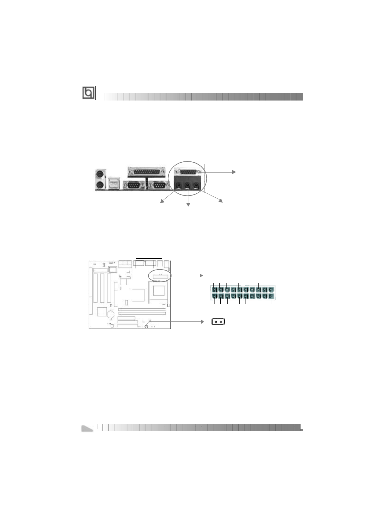
Provideson-boardLine-inJack,Speaker-outJack andMicrophone-inJack.
Advancedfeatures
l
PCISpec.2.2compliant.
l
ProvidesAnti-Virusfunction.
l
Provideson-boardPS/2mouseandPS/2keyboardports.
l
TwoUSB portssupported.
l
Providesinfrared interface.
l
SupportsWindows95/98softwarepower-down.
l
Supportswake-up onLANand wake-up oninternal/externalmodem.
l
Supportsautofan off whenthesystementerssuspend mode.
l
Providesonboard3.3VregulatortosupportATXpowersupplywithout3.3Voutput.
l
On-boardWinbond W83782Dsupportssystemmonitoring(monitorsCPUandsystem
temperature,voltages,chassisintrusionand fanspeed).(manufacturing option)
l
ProvidesmanagementapplicationsuchasManageEasyandLDCM(LANDesk®Client
Manager).(manufacturing option)
l
Supportskeyboardpasswordpower-on function.
l
SystemstatusresumesafterACpowerfailure.
l
ProtectsthesystemBIOSfrombeing attackedbyseverevirussuchasCIH,by
enabling “FlashWriteProtect”inCMOSsetup.
Introduction
2

ManualforLegenX8
BIOS
l
Licensed advancedAWARD BIOS,supportsflashROMwith2MBmemorysize,
plug and playready.
l
SupportsIDECD-ROMorSCSIbootup.
Greenfunction
l
SupportsACPI(AdvancedConfigurationand PowerInterface)and ODPM(OS
DirectedPowerManagement).
l Supportsthree greenmodes:Doze,Standbyand Suspend.
Expansionslots
l 1ISAslotand 3PCIslots.
l 1AGPSlot.
3
Chapter1

ManualforLegenX8
4
--Thispage isintentionallyleftblank--

ManualforLegenX8
Chapter2
InstallationInstructions
Chapter2
InstallationInstructions
ThissectioncoversExternalConnectors,JumperSettingsand MemoryConfiguration.Re-
fertothemotherboardlayoutchartforlocationsofall jumpers,externalconnectors,slots
and I/Oports.Furthermore,thissectionlistsall necessaryconnectorpinassignmentsfor
yourreference.Theparticularstateofthejumpers,connectorsand portsareillustratedin
thefollowingfigures.Beforesetting thejumpersorinserting theseconnectors,pleasepay
attentiontothedirections.
BesuretounplugtheACpowersupplybeforeaddingorremovingexpansion
cardsorothersystemperipherals,otherwiseyourmotherboardandexpan-
sion cardsmightbeseriouslydamaged.
ExternalConnectors
PS/2KeyboardConnector,PS/2Mouse Connector
PS/2keyboardconnectorisfortheusageofPS/2keyboard.If using astandardATsize
keyboard,anadaptershouldbeusedtofitthisconnector.PS/2mouseconnectorisforthe
usage ofPS/2mouse.
USB1,USB2
TwoUSB portsareavailableforconnecting USB devices.
ParallelPortConnectorandSerialPortConnector(UART1,UART2)
Theparallelportconnectorcanbeconnectedtoaparalleldevicesuchasaprinter,while
theserialportconnectorscanbeconnectedtoserialportdevicessuchasaserialport
mouse.You canenable/disablethemand choosethe IRQorI/Oaddressin“Integrated
Peripherals”fromAWARDBIOSSETUP.
chapter2
5
PS/2MouseConnector
PS/2KeyboardConnector
USB1
USB2
ParallelPort
UART2
UART1

ManualforLegenX8
Line-injack,Microphone-injack,Speaker-outjack and
MIDI/Joystickconnector
TheLine-injack canbeconnectedtodevicessuchasacassetteorminidisc playerfor
playback orrecording.TheMicrophone-injack canbeconnectedtoamicrophonefor
voiceinput. TheSpeaker-outjack allowsyoutoconnectspeakersorheadphonesfor
audiooutputfromthe internalamplifier.
TheMIDI/Joystick connectorallowsyoutoconnectagamejoystick oraMIDIdevice.
ATXPowerSupplyConnector&PowerSwitch(POWER)
Besuretoconnectthepowersupplyplug tothisconnectorinitsproperorientation.The
powerswitch(POWER)shouldbeconnectedtoamomentaryswitch.Whenpowering up
yoursystem,firstturnonthemechanicalswitchofthepowersupply(ifoneisprovided),
then pushoncethepowerbutton.Whenpoweringoff thesystem,youneedn’tturnoffthe
mechanicalswitch,justPushonce*thepowerbutton.
Note:*Ifyou change“soft-off byPWR-BTTN”fromdefault“Instant-off”to“Delay
4Secs”inthe“POWERMANAGEMENTSETUP”sectionoftheBIOS,thepower
buttonshouldbepressedformorethan4secondsbeforethesystempowers
down.
HardDiskLEDConnector(HD_LED)
Theconnectorconnectstothecase’sIDEindicatorLEDindicating theactivitystatusof
IDEharddisk.
ResetSwitch(RESET)
Theconnectorconnectstothecase’sresetswitch.Press theswitchonce,thesystem
resets.
Installation Instruction
6
MIDI/Joystick
SpeakeroutLineinMicrophonein
POWER
5V5V-5VGNDGNDGNDPSON
GND-12V3.3V
12V5VSBPS-OKGND5VGND5VGND3.3V3.3V
ATXPowerSupplyConnector
1
20

ManualforLegenX8
SpeakerConnector(SPEAKER)
Theconnectorcanbeconnectedtothespeakeronthecase.
PowerLEDConnector(PWR_LED)
ThepowerLEDhasthree status.WhennoACpowersupplyispresent, theLEDisoff.
Whenthesystemisinsoft power-downstatus,theLEDglowsdimly.When thesystem
ispoweredup,theLEDison.
Key-LockConnector(KEY_L)
Theconnectorcanbeconnectedtothekeyboardlock switchon thecaseforlocking the
keyboard.
ACPILEDConnector(GREEN_LED)
TheACPILEDhasthree status.Whenthesystemisinpower-off status,theLEDisoff.
When thesystemispoweredup,theLEDison.Whenthe systementerssuspend mode,
theLEDwill flash.
HardwareGreenConnector(SLEEP)
Pushoncetheswitchconnectedtothisheader,thesystementerssuspend mode.
chapter2
7
POWER
PWR_LED
KEY_L
GREEN_LED
HD_LED
RESET
SPEAKER
SLEEP
LED+
LED-
GND
RESET
SPKDATA
NC
GND
VCC
GND
POWER
LED+
LED-
LED-
KEYLOCK
GND
LED+
LED-
LED-
SLEEP
GND

ManualforLegenX8
InfraredHeader(IrDA)
Thisconnectorsupportswireless transmitting and receiving.Ifusing thisfunction,set
“SerialPort2Mode”toIrDAorASKIRandconfigurethesettingsfromthe“INTEGRATED
PERIPHERALS”sectionoftheBIOS.
FanConnector(CPUFAN,CHSFAN)
Thesetwofansarecontrollable.Theywillbeautomaticallyturnedoffafterthe system
enterssuspendmode.YoualsocanchoosenottoturntheCPUFANoffbysetting“CPUFAN
OffInSuspend”asDisabled inthe“POWERMANAGEMENTSETUP”sectionoftheBIOS.
Wake-UpOnLAN (WOL)
ThroughtheWake-UpOnLANfunction,awakeeventoccurringfromthe networkcan
wakeupthesystem.Ifthisfunction istobeused,pleasebe sureanATX2.01power
supplyofwhich5VSB lineiscapableofdelivering 720mA,andaLANadapterwhich
supportsthisfunctionareused.Thenconnectthisheadertotherelevantconnectoronthe
LANadapter,set“ResumebyRing/LAN”asEnabledinthe“POWERMANAGEMENTSETUP”
sectionoftheBIOS.Save&exit, thenbootthe operating systemoncetomakesurethis
function takeseffect.
Installation Instruction
8
VCC
IRRX
GND
IRTXNCVCC
FANGND
CHSFAN
+12V
SENSE
FANGND(Controllable)
+12V
SENSE
CPUFAN
1+5Vstandby
GND
Signalforwakingup(activehigh)

ManualforLegenX8
Wake-UpOnInternalModem(WOM)
ThroughtheWake-UpOnInternalModemfunction,thesystemwhichisinthepower-off
statuscanbepoweredon byaringsignalreceived fromtheinternalmodem.Ifthisfunction
istobeused,besureaninternalmodemcardwhichsupportsthefunctionisused.Then
connectthisheadertothe relevantconnectoronthemodemcard,set“ResumebyRing/
LAN”toEnabled inthe“POWERMANAGEMENTSETUP”section ofthe BIOS.Save&exit,
thenboottheoperating systemoncetomakesurethisfunctiontakeseffect.
DigitalAudioConnector(JP6)
JP6isaCDaudioconnectorwhichcanbeconnectedtoaCD-ROMdrive(Sonystan-
dard)throughaCD audiocable.
HardwareVolumeControl(S1,S2)
Theonboardaudioallowsvolumecontrolwithapush-switchoperation.Asingle-pushon
the S2switchincreasesvolumelevelby1.5dB,whileasingle-pushon the S1switch
attenuatesitby1.5dB.SimultaneouspushingbothswitchesS1andS2enablesouput
muting.
chapter2
9
CDLeft
channelCDRight
channel
GNDGND
1+5Vstandby
GND
Signalforwakingup(activelow)
S2S1
JP6

ManualforLegenX8
Expansion Slots&I/O Portsdescription
Slot/PortDescription
ISA1ISAslot.
PCI1FirstPCIslot.
PCI2SecondPCIslot.
PCI3ThirdPCIslot.
IDE1PrimaryIDEport.
IDE2SecondaryIDEport.
FLOPPYFloppyDrivePort.
AGP AcceleratedGraphics Port.
JumperSettings
Jumpersarelocatedonthemotherboard,theyrepresent,clearCMOSjumperJCC,enable
keyboardpasswordpower-onfunctionjumperJKB,andenable/disableonboardaudio
jumperJP8.Pin1foralljumpersarelocatedonthesidewithathick whiteline(Pin1→
),referring tothe motherboard’ssilkscreen.Jumperswiththreepinswill be
shownastorepresentpin1 &pin2 connectedandtorepresentpin2 &
pin3 connected.
ClearCMOS(JCC)
If youwanttoclearCMOS,unplugtheACpowersupplyfirst, closeJCC (pin1&pin2)once,
setJCC back tothenormalstatuswithpin2 &pin3 connected,thenpoweronthesystem.
Enable/Disableon-boardaudio(JP8)
Ifyouwanttousetheon-boardaudio,closeJP8(default).Otherwise,setJP8opento
disabletheon-boardaudio.
Installation Instruction
10
Normalstatus:
ClearCMOS:
321
JCC
JCC
(UnplugtheACpowersupply)
Enableon-boardaudio:
Disableon-boardaudio:
JP8
JP8
321

ManualforLegenX8
Enablekeyboardpasswordpower-onfunction (JKB)
Themotherboardprovidestheadvancedkeyboardpasswordpower-onfunction.When
wanting tousethisfunction,setJKB withpin1 &pin2 closed.Otherwise,setJKBwithpin2
&pin3 closedfordisabling thisfunction.
Inordertoimplementthisfunction,set“POWERONFunction”toPasswordandsetthe
keyboardpower-onpasswordinthe “INTEGRATEDPERIPHERALS”sectionoftheBIOS.
Saveand exit, then poweroff yoursystem.Inthiscase,thepowerbutton’spower-on
functionhasbeendisabled.The onlywaytopowerup the systemistoenterthecorrect
password.Ifyouforgetthepassword,clearCMOSand setitagain.
Note:1.Ifwanting tousethisfunction,5VSBlineofthepowersupplyshouldbe
capableofdeliveringenough current(eg.200mA)forallthedevicescon-
nectedtothekeyboardport,ifnot,you willbeunabletopowerup the
systemusingthekeyboard.
2.Ifyou setJKBwithpin2&pin3closed,set“POWERONFunction”to
BUTTONONLY,don’tsetittoPassword,orthiswill preventyoufrom
poweringupyoursystem.
3.Ifyou encountertheaboveproblems,clearCMOSandsetthejumper
andBIOSoptionagain.
MemoryConfiguration
Thismotherboardprovidestwo168 pin3.3Vun-bufferedDIMMsocketstosupportaflexible
memorysizeranging from8MB/256MBforSDRAMorfrom8MB/512MBforEDOmemory.
Thefollowing setofrulesallowsforoptimumconfigurations.
Rulesforpopulating a440LXmemoryarray:
l TheDRAMTiming register,whichprovidestheDRAMspeedgradecontrolforthe entire
memoryarray,mustbeprogrammed tousethetimingoftheslowestDRAMsinstalled.
l PossibleSDRAMDIMMmemorysizesare8MB,16MB,32MB,64MB,128MBineachDIMM
socket.
l PossibleEDODIMM memorysizesare8MB,16MB,32MB,64MB,128MB,256MBineach
DIMMsocket.
chapter2
11
Disable:
Enable:
JKB
JKB
1
2
3
1
2
3

ManualforLegenX8
12
--Thispage isintentionallyleftblank--

ManualforLegenX8
Chapter3
BIOSDescription
Chapter3
BIOSDescription
UtilitySupport:
FLASH.EXE
Thisisaflashmemorywrite/readutilityusedforthe purposeofupgrading yourBIOSwhen
necessary.Beforedoing so,pleasenote:
lWestronglyrecommend youonlyupgradeBIOSwhenencountering problems.
lBeforeupgradingyourBIOS,reviewthedescription belowtoavoidmaking
mistakes,destroyingtheBIOSandresultinginanon-working system.
When youareencounteringproblems,forexample,youfind yoursystemdoesn’tsupport
the newCPUwhichisreleased afterourcurrentmotherboard,youmaythereforeupgrade
theBIOS.
Followthestepsexactlyforasuccessfulupgrade.
1.Createabootablesystemfloppydiskette,bytypingFormatA:/sfromtheDOSprompt
underDOS6.xxorWindows9xenvironment.
2.CopyFLASH.EXEfromthe directory\Utilitylocatedon the QDIMotherboardUtilityCD
ontoyournewbootablediskette.
3.Downloadtheupdated BIOSfilefromtheWebsite(http://www.qdigrp.com).Please
besuretodownloadthesuitableBIOSfileforyourmotherboard.
4.Uncompress thefiledownload,copytheBIOSfile(xx.bin)ontothebootablediskette,
and notethechecksumofthisBIOSwhichislocatedinreadmefile.
5.Rebootthe systemfromthebootablediskettecreated.
6.Then run the FLASHutilityattheA:\prompt. During theprocess,thesystemwill
prompt:‘DoyouwanttosavetheBIOS(Y/N)’.Ifyoutype ‘Y’,the systemwillprompt
fortheBIOSname.Thesystemwill alsodisplaythechecksumwhichshouldbe
exactlythesameasthechecksumyoucopiedfromthe readmefile.Don’tturnoff
powerorresetthesystemuntil the BIOSupgradehasbeencompleted.
Concerning howtorun the FLASHutility,pleaserefertothefollowing descriptions:
Usage:FLASH[BIOSfile][/c[<command...>]][/n]
FLASH[BIOSfile][/g]
/c:Flashing memorywill clearprevioussettings.Defaultallowssettingstoremain.
<command>functiondefinition:
c:clearCMOS;
p:clearPnP;
d:clearDMI.
13
Chapter3

ManualforLegenX8
/n:programsBIOSwithoutprompting.Ifthisoptionischosen:
BesureyournewBIOSiscompatiblewithyourMB.If not, thesystemwill
bedamaged.
/g:RetrievesBIOSfilefromBIOSROM.
Examples:
A:\FLASH.EXEBIOSfile.bin
A:\FLASH.EXEBIOSfile.bin/cdpc/n
A:\FLASH.EXEBIOSfile.bin/g
Note:FLASHutilityrunsincorrectlyatWindowsDOSprompt.
14
AwardBIOSDescription

ManualforLegenX8
Chapter3
15
AWARD BIOSDescription
Entering Setup
Poweron thecomputer,whenthefollowing messagebrieflyappearsatthebottomofthe
screenduringthePOST(PowerOnSelfTest),press <Del>keyorsimultaneouslypress
the<Ctrl>+<Alt>+<Esc>keys,toentertheAWARD BIOSCMOSSetup Utility.
Press <Del>toenterSETUP
Onceyou haveentered,theMainMenu(Figure1)appearson the screen.The mainmenu
allowsyou toselectfromelevensetupfunctionsandtwoexitchoices.Usethe arrow
keys toselectamong theitemsand press the<Enter>keytoacceptorenterthesub-
menu.
Figure-1MainMenu
Note:The“SystemMonitor”itemwill notbedisplayedifthereisno system
monitorchipsonthemotherboard.
LoadSetupDefaults
The SetupDefaultsarecommon and efficient. It isrecommendedthatusers
loadthesetup defaultsfirst, thenmodifytheneeded configurationsettings.
StandardCMOSSetup
ThebasicCMOSsettingsincludedin“StandardCMOSSetup”areDate,Time,HardDisk
DriveTypes,FloppyDiskDriveTypes,andVGAetc.Usethearrowkeys tohighlight
theitem,then usethe<PgUp>or<PgDn>keys toselectthevalueyouwantin
eachitem.

ManualforLegenX8
Figure-2StandardCMOSSetupMenu
HardDisk
PrimaryMaster/PrimarySlave/SecondaryMaster/SecondarySlave
ThesecategoriesidentifytheHDDtypesof2IDEchannelsinstalled inthecomputersystem.
Therearethree choicesprovidedfortheEnhancedIDEBIOS:None,Auto,and User.
“None”meansnoHDDisinstalledorset;“Auto”meansthe systemcanauto-detectthe hard
disk when booting up;bychoosing“user”,therelatedinformation shouldbeenteredregard-
ingthe followingitems.Entertheinformationdirectlyfromthekeyboardandpress <Enter>:
CYLSnumberofcylindersHEADnumberofheads
PRECOMPwritepre-compensationLANDZlandingzone
SECTORnumberofsectorsMODEHDDaccessmode
Video
Setthisfieldtothetypeofvideo displaycardinstalledinyoursystem.
EGA/VGAEnhancedGraphics Adapter/Video GraphicArray.ForEGA,
VGA,SEGA,SVGA,orPGAmonitoradapters.
CGA40 ColorGraphicAdapter,powering upin40 columnmode.
CGA80 ColorGraphicAdapter,powering upin80 columnmode.
MONOMonochromeadapter,including high resolutionmonochrome
adapters.
AwardBIOSDescription
16
Table of contents
Other QDI Motherboard manuals

QDI
QDI K8VM800 User manual

QDI
QDI BA1 User manual

QDI
QDI KinetiZ 7E User manual

QDI
QDI P5I430TX Titanium IB+ User manual

QDI
QDI P6I440LX/DP User manual

QDI
QDI Brilliant IV User manual

QDI
QDI PlatiniX 2E/333 User manual

QDI
QDI P4I848P User manual

QDI
QDI PlatiniX 1E User manual

QDI
QDI PENTIUM II P6I440EX/ATX EXCELLENT 1 User manual

QDI
QDI PlatiniX 1 User manual

QDI
QDI PlatiniX 8 Series User manual

QDI
QDI SynactiX 5EP User manual

QDI
QDI CenturieX 1 User manual

QDI
QDI PlatiniX 7B User manual

QDI
QDI BrillianX 1S/2000 User manual

QDI
QDI Advance 10TM User manual

QDI
QDI CenturieX 2 User manual

QDI
QDI P61440FX Commander User manual

QDI
QDI K8N4 Series User manual