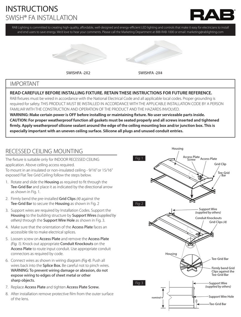
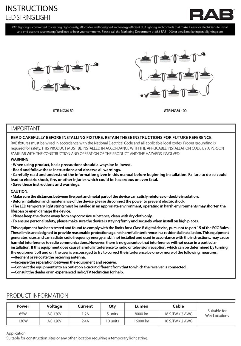
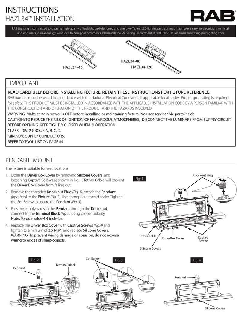
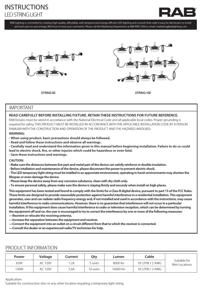
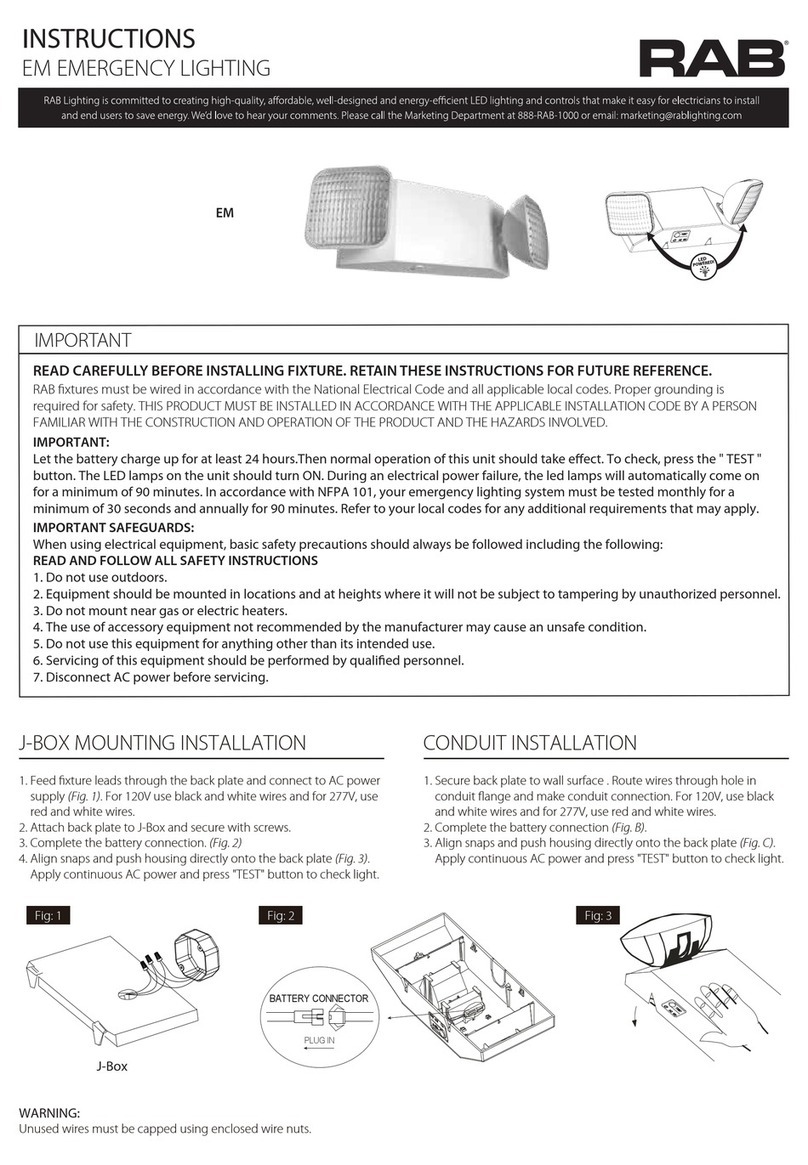
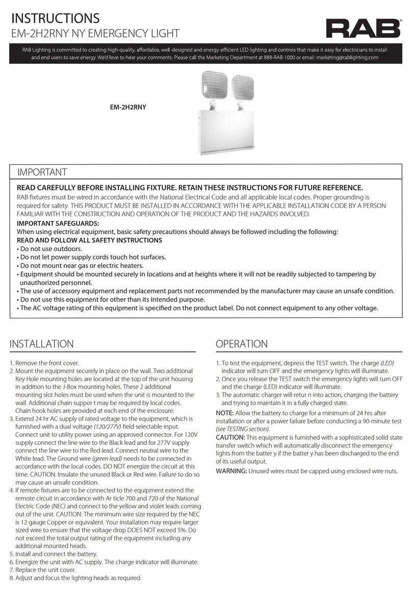
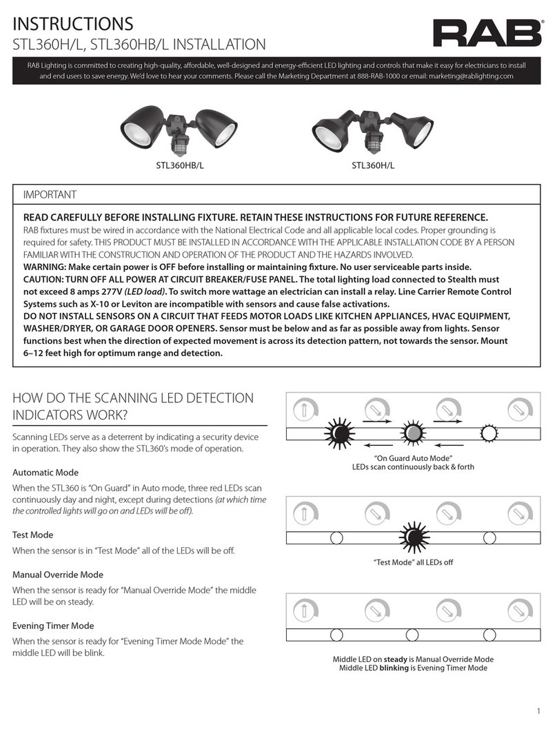
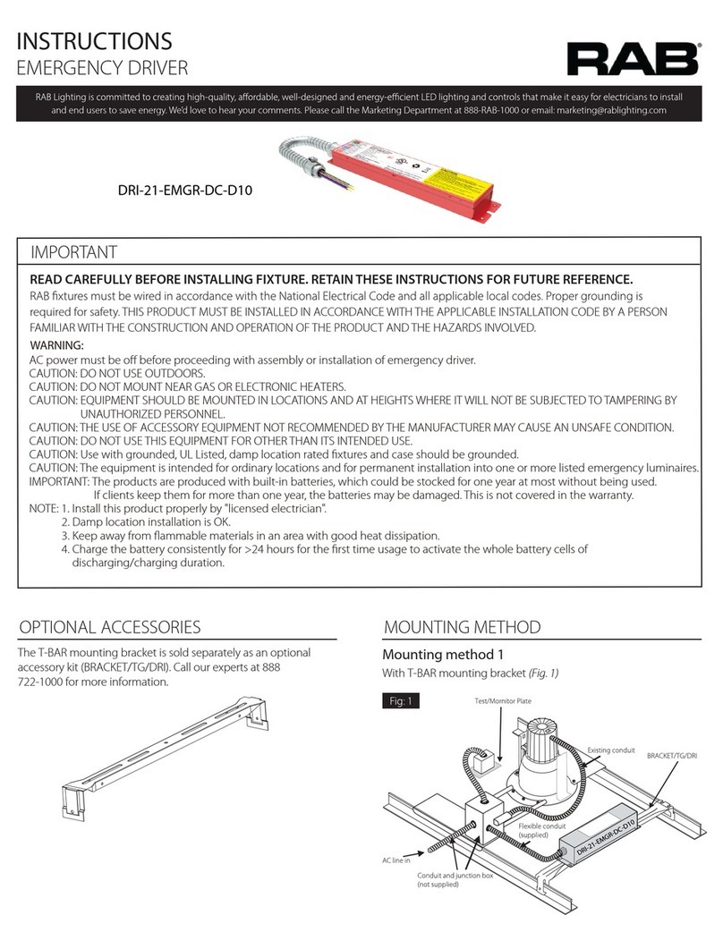
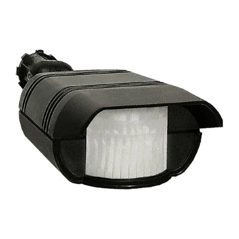
RAB TOMO- 2FT User manual

INSTRUCTIONS
FIELD-ADJUSTABLE TOMO™ INSTALLATION
Secure Surface Mounting Plate to Junction Box (by
others). (Additional attachment to the ceiling may be
needed for longer xtures ). TOMO includes a 2nd
Surface Mounting Plate and Surface Mount Adaptor
Plate (see Fig. 2).
2. Remove End Caps
Housing CoverLens and Tray Assembly
sliding the Housing CoverKey
Slots . Pre-installed Tether Cables (2)
Lens and Tray Assembly
Housing Cover
(by others) through
Surface Mounting Plate.
4. Align Surface Mount Adaptor Plate to the Housing
Cover. Using (4) Screws (provided) secure to the Surface
Mounting Plate.
5.
6. Push Lens and Tray Assembly into the Housing Cover.
Align Keys into Key Slots
Housing Cover into the Lens and Tray Assembly
on End Caps.
WARNING: To prevent wiring damage or abrasion, do
not expose wiring to edges of sharp objects.
TOMO- 2FT
End Cap (2)
Surface Mounting Plate
Housing Cover
IMPORTANT
READ CAREFULLY BEFORE INSTALLING FIXTURE. RETAIN THESE INSTRUCTIONS FOR FUTURE REFERENCE.
WARNING: Make certain power is OFF before installing or maintaining xture. No user serviceable parts inside.
The xture is suitable for indoor applications. Suitable for damp locations. Ceiling, Canopy and Pendant mount only.
TOMO- 4FT TOMO- 8FT
Surface Mount Adaptor Plate
Lens and Tray Assembly
Screws (4)
Tether Cable (2)
Lens and Tray Assembly
Key Slot
Housing Cover
Surface Mount Adaptor Plate

INSTRUCTIONS
FIELD-ADJUSTABLE TOMO™ INSTALLATION
Cable
Junction Box
(sold separately)
Cross Bar
Locknut
Canopy
with Power
Cord
1/4- 20 Stud
Strain Relief
Canopy
Rings
Power Cord
Fixture
Cable Coupler
Cable Coupler Nut
Strain Relief
Cable Coupler
Power Cord through the hole on Canopy and tighten
Strain Relief. Slide Power Cord through the hole on
CanopyStrain Relief. Orient the Fixture so
that the CanopyPower Cord
Cross Bar on Junction Box.
CanopyCable
Coupler on the 1/4-20 Stud and tighten the Fixture.
4. Canopy and Cable Power Cord
1/4 -20 Stud
5. Push Lens and Tray Assembly into the Housing Cover.
Align Keys into Key Slots
Housing Cover into the Lens and Tray Assembly
End Caps.
WARNING: To prevent wiring damage or abrasion, do
not expose wiring to edges of sharp objects.
Knockouts
1. Remove End Caps. Slide Lens Tray AssemblyHousing
Cover to release Tray AssemblyHousing Cover
Key Slots as
Tether Cables (2)
Lens and Tray AssemblyHousing
Cover
2. For Canopy Mounting, remove Knockouts on the Housing
Cover Cable Coupler
Housing CoverKnockouts.
Cable CouplerCable Coupler Nut onto the
Housing Cover
4. Insert the Cable into the Cable Coupler
the Cable and tighten the Locknut
5. Attach the CanopyPower Cord to the Housing Cover
Cord
Retainer Housing Cover.
6. Loosen the Locknut on Cable Coupler.
7. Rotate the Locknut and tighten.
Power Cord through the Canopy Rings. Adjust the
Power Cord and tighten it on the Canopy
Strain Reliefs.
9. Mount all CanopiesCable
length.

INSTRUCTIONS
FIELD-ADJUSTABLE TOMO™ INSTALLATION
FIELD ADJUSTMENT
Color (CCT) Selection Switch
Power (W) Selection Switch
TOMO-2
TOMO-4
TOMO-8
Power (W) Selection Switch
Color (CCT) Selection Switch
Power (W) Selection Switch
(sold separately).
Note: Continuous Run Mounting is not available with
LIGHTCLOUD® /LC, /LC/E sux.
End Caps (Fig. 6)
Silicone PlugsTOMO CONNECT
(ordered separeately)
installation (Fig. 7). TOMO CONNECT(2) Fixing
Screws. Install Fixing Screws in Silicone Plug(1) one
Fixture(Fig. 8).
2. CAUTION:
(120V through 277V only).
WARNING: To prevent wiring damage or abrasion, do not expose
wiring to sharp objects.
Catalog #
TOMO-2
TOMO-4
Maximum Number of Linked Fixtures
28
14
7
TOMO CONNECT
Fixing Screws
Silicone Plug
TOMO
CONNECT
Color Temperature
(CCT ) and Power (W)
Remove End Caps. Slide Lens Tray AssemblyHousing
Cover to release Tray AssemblyHousing Cover
Key Slots
. Pre-installed Tether Cables (2)Lens and Tray
AssemblyHousing Cover
.
2. Lens & Tray Assembly as
(Fig. 9, 10, 11). Note:
TOMO-8 is equipped with two (2) Color Temperature (CCT)
switches and (2) two Power (W) switches.
Select a Color Temperature (CCT) and Power (W)
4. Lens
and Tray Assembly into the Housing Cover. Align Keys into Key
SlotsHousing Cover into the
Lens and Tray AssemblyEnd Caps.
WARNING: To prevent wiring damage or abrasion, do not
expose wiring to edges of sharp objects.

INSTRUCTIONS
FIELD-ADJUSTABLE TOMO™ INSTALLATION
CAUTION: Be sure xture temperature is cool enough to touch.
Do not clean or maintain while xture is energized.
2.
the LEDs.
Note: These instructions do not cover all details or variations in equipment
nor do they provide for every possible situation during installation, operation
or maintenance.
2.
4.
5.
6.
PINK
LIGHT
FIXTURE
Vaux 12V
YELLOW
GROUND
GROUND
( - ) DIM V
( + ) DIM V
COMMON
LINE BLACK
WHITE
PURPLE

INSTRUCTIONS
FIELD-ADJUSTABLE TOMO™ INSTALLATION
OPERATION
Note: These instructions do not cover all details or variations in equipment
nor do they provide for every possible situation during installation,
operation or maintenance.
LIGHT
FIXTURE
INSIDE FIXTURE
BATTERY
Pink/DIM–
Black/Switched Line
Green/Ground
White/Neutral
Black/Unswitched Line
Purple/DIM+
BACKUP
DRIVER
BATTERY
CONNECTOR:
CONNECT
ONLY AFTER
AC SUPPLY
POWER IS
CONNECTED
TOMO - IN -0822 RAB WARRANTY: RAB’s warranty is subject to all terms and conditions found at rablighting.com/warranty.
Easy Answers
rablighting.com
Visit our website for product info
Tech Help Line
Call our experts: 888 722-1000
e-mail
Answered promptly - sales@rablighting.com
Free Lighting Layouts
Answered online or by request
© 2022 RAB LIGHTING Inc.
CAUTION: FOR BATTERY BACKUP FIXTURE (TOMO-4/TOMO-8)
BATTERY.
BATTERY connector until installation is
(Fig. 13).
NOTE: Make sure that the necessary branch circuit wiring is
available. An UNSWITCHED AC source of power is required. The
emergency driver must be fed from the same branch circuit as the
LED driver.
CAUTION: Do not use any supply voltage other than 120-277V
50/60 HZ.
UNSWITCHED HOT HOT AC
line.
2. UNSWITCHED circuit, connect UNSWITCHED
and SWITCHED lines together.
SWITCHED circuit, connect SWITCHED HOT AC
xture lead to the external control.
4. DIMDIM
5. GROUND
ground. Do not connect GROUND
6.
7.
BATTERY (Fig. 13).
Charging Indicator Light should illuminate to indicate the
9. Once the BATTERY
is illuminated indicating that the BATTERY
charged.
2.
automatically returns to charging mode.
2.
Test Button (Fig. 14)
2.
P-100173
Test Button
This manual suits for next models
2
Table of contents
Other RAB Lighting Equipment manuals

RAB
RAB PLC-9-V-8XX-BYP User manual

RAB
RAB SWISHFA -2X2 User manual

RAB
RAB STRINGER34 User manual

RAB
RAB STL200H/L User manual

RAB
RAB SHARK - 8FT User manual

RAB
RAB STL360HB/L User manual

RAB
RAB GOTCHA PLUS GT500 User manual

RAB
RAB GUS- 2FT User manual

RAB
RAB DRI-21-EMGR-DC-D10 User manual

RAB
RAB PLL-14-8 DIR Series User manual