Page 10 of 14 CP0460
R&G
Unit 1, Shelley’s Lane, East Worldham, Alton, Hampshire, GU34 3AQ
Tel:
+44
(0)1420
89007
Fax:
+44
(0)1420
87301
www.rg-racing.com Email: [email protected]m
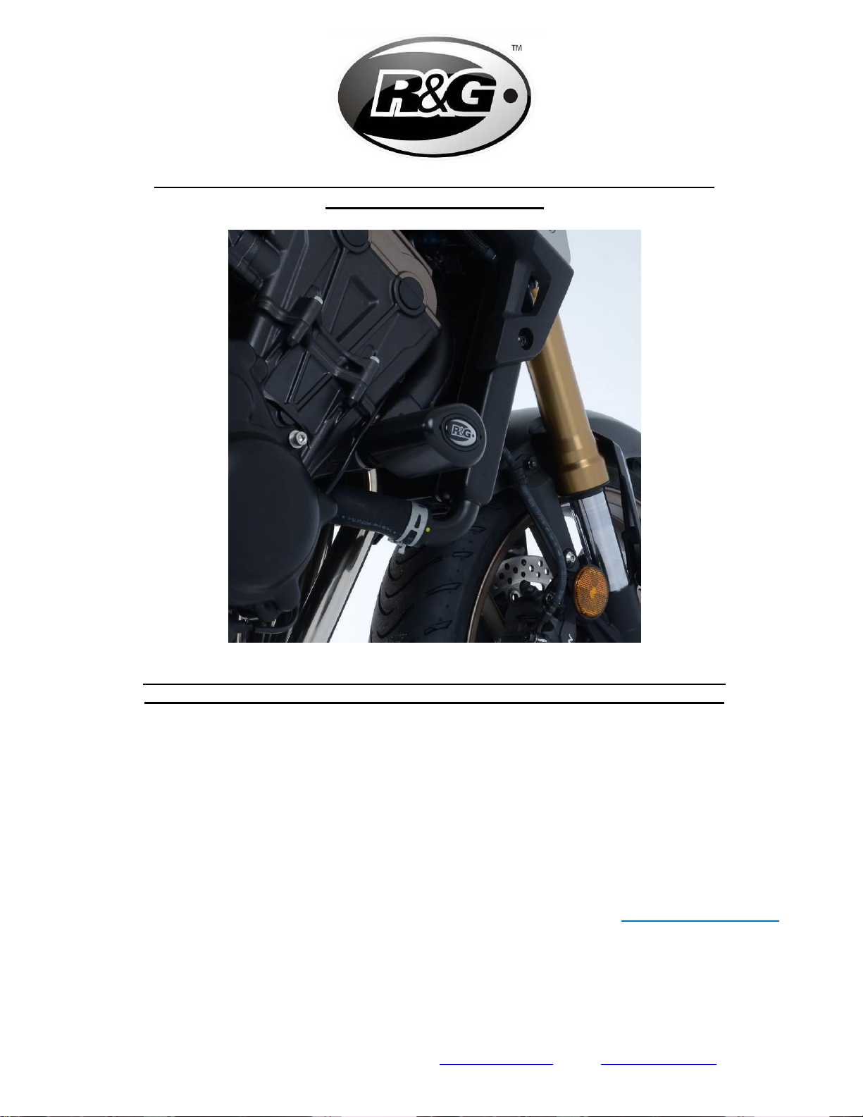
•Laisser la rondelle d’origine en place (comme sur la photo 2), faire passer le boulon et la
protection à la place du boulon de moteur côté gauche précédemment retiré, comme
indiqué sur la photo 3.
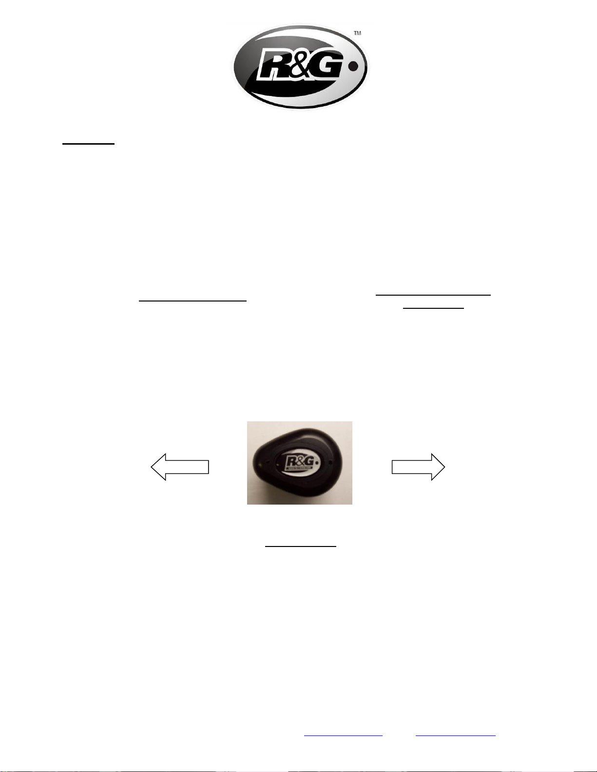
•VEUILLEZ NOTER QUE LA PROTECTION CRASH DOIT ÊTRE POSITIONNÉE COMME SUR LA
PHOTO ‘A’ AVEC LA PLUS GRANDE EXTRÉMITÉ VERS L'AVANT DE LA MOTO.
•Serrez le boulon au couple spécifié par le fabricant, en veillant à ce que la protection et
l’entretoise soient bien serrées contre le cadre, comme sur la photo 3.
Côté droit (lorsqu’on est assis sur la moto)
•Le côté droit s’ajuste de la même manière que le côté gauche. À l’aide de votre cliquet,
retirez le boulon moteur du côté droit, voir fleche sur la photo 4.
•Assemblez l’assemblage du côté droit comme indiqué sur le schéma d’assemblage côté
droit (page 2), en veillant à utiliser le boulon le plus court 100mm M12 (article 8).
•Faites ensuite glisser la rondelle M12 (article 5), puis la rondelle de blocage (article 6) et
une bobine de protection crash (article 1) de façon à ce que le bord dentelé de la
rondelle de blocage repose contre la face intérne de la bobine.
•Placez l’entretoise droite S0027 (article 4) sur l’extrémité du boulon dépassant de la
bobine.
Laisser la rondelle d’origine en place (comme sur la photo 2), faire passer le boulon et la
protection à la place du boulon de moteur côté droit précédemment retiré, comme
indiqué sur la photo 4.
•VEUILLEZ NOTER QUE LA PROTECTION CRASH DOIT ÊTRE POSITIONNÉE COMME SUR LA
PHOTO ‘A’ AVEC LA PLUS GRANDE EXTRÉMITÉ VERS L'AVANT DE LA MOTO
•Serrez le boulon au couple spécifié par le fabricant, en veillant à ce que la protection et
l’entretoise soient bien serrées contre le cadre, comme sur la photo 5.
•Si cela n’est pas déjà fait, insérer les stickers en caoutchouc dans le creux des 2
capuchons de protection crash.
•Insérer les capuchons de protection crash dans les 2 protections crash, voir photo 6.
ISSUE 3 - 22/05/2019 (DM)
CONSUMER NOTICE
The catalogue description and any exhibition of samples are only broad indications of the Products and R&G may make design changes
which do not diminish their performance or visual appeal and supplying them in such state shall conform to the order. The Buyer
acknowledges no representation or warranty (other than as to title) has been given or will apply to the Products other than those in
R&G’s order or confirmation and the Buyer confirms it has chosen the Products as being of merchantable quality and suitable for its
particular purposes. Where R&G fits the Products or undertakes other services it shall exercise reasonable skill and care and rectify any
fault free of charge unless the workmanship has been disturbed. The Buyer is responsible for ensuring that the warranty on the
motorcycle is not affected by the fitting of the Products. On return of any defective Products R&G shall at its option either supply a
replacement or refund the purchase money but shall not be liable if the Products have been modified or used or maintained otherwise
than in accordance with R&G’s or manufacturer’s instructions and good engineering practice or if the defect arises from accident or
neglect. Other than identified above and subject to R&G not limiting its liability for causing death and personal injury, it shall not be liable
for indirect or consequential loss and otherwise its liability shall be limited to the amounts paid by the Buyer for the Products or the fitting
or service concerned. These terms do not affect the Buyer’s statutory rights.
R&G RETURNS POLICY (NON-FAULTY GOODS)
Returns must be pre-authorised (if not pre-authorised the return will be rejected). Goods may only be returned direct to us if they were
purchased direct from us (customer must prove if necessary). Otherwise to be returned to original vendor. Goods must be in re-sellable
condition, in the opinion of R&G. All returns are subject to a 25% restocking and handling fee (25% of the gross value exc. P&P –at the
prevailing price at time of purchase). The customer must pay any and all carriage charges. No returns of discontinued products, unless
within 14 days of purchase. This policy does not affect your statutory rights and does not refer to faulty goods.