Page 6of 12 TG0018
R&G
Unit 1, Shelley’s Lane, East Worldham, Alton, Hampshire, GU34 3AQ
Tel:
+44
(0)
1420
8900
7
Fax:
+44
(0
)
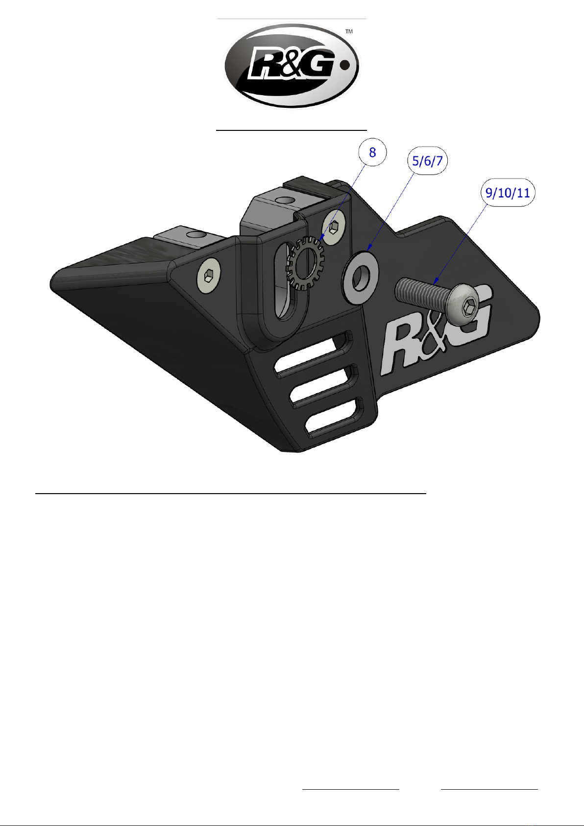
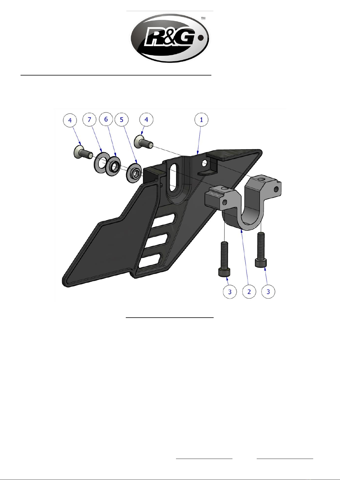
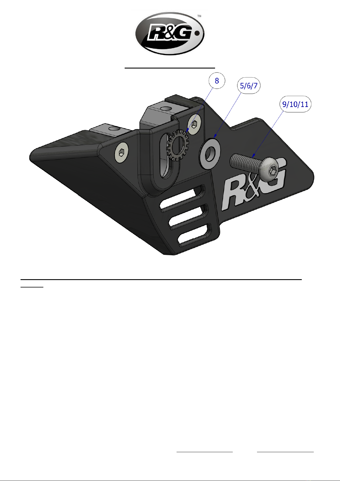
1420 87301 www.rg-racing.com Email: in[email protected] •Slide the Chain & Sprocket guard (item 1) onto the outer slots of the mount block (item 2) and
secure using the two countersunk M6 bolts (item 4) as shown in Assembly diagram 3,
tightened to the correct torque.
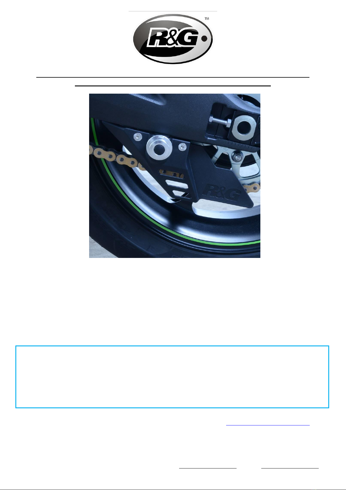
•If fitting in conjunction with Cotton Reels, refer to the legend to select the correct size
compression sleeve or washer and locate the small boss (if applicable) into the vertical Cotton
Reel slot from the outside and fit Cotton Reel as shown in the example below (in this case, the
anti-rotation washer is not required).
ISSUE 2 12/04/2021 (DM)
CONSUMER NOTICE
The catalogue description and any exhibition of samples are only broad indications of the Products and R&G may make design
changes which do not diminish their performance or visual appeal and supplying them in such state shall conform to the order.
The Buyer acknowledges no representation or warranty (other than as to title) has been given or will apply to the Products other
than those in R&G’s order or confirmation and the Buyer confirms it has chosen the Products as being of merchantable quality
and suitable for its particular purposes. Where R&G fits the Products or undertakes other services it shall exercise reasonable
skill and care and rectify any fault free of charge unless the workmanship has been disturbed. The Buyer is responsible for
ensuring that the warranty on the motorcycle is not affected by the fitting of the Products. On return of any defective Products
R&G shall at its option either supply a replacement or refund the purchase money but shall not be liable if the Products have
been modified or used or maintained otherwise than in accordance with R&G’s or manufacturer’s instructions and good
engineering practice or if the defect arises from accident or neglect. Other than identified above and subject to R&G not limiting
its liability for causing death and personal injury, it shall not be liable for indirect or consequential loss and otherwise its liability
shall be limited to the amounts paid by the Buyer for the Products or the fitting or service concerned. These terms do not affect
the Buyer’s statutory rights.
R&G RACING RETURNS POLICY (NON-FAULTY GOODS)
Returns must be pre-authorised (if not pre-authorised the return will be rejected). Goods may only be returned direct to us if
they were purchased direct from us (customer must prove if necessary). Otherwise to be returned to original vendor. Goods
must be in re-sellable condition, in the opinion of R&G Racing. All returns are subject to a 25% restocking and handling fee (25%
of the gross value exc. P&P –at the prevailing price at time of purchase). The customer must pay any and all carriage charges.
No returns of discontinued products, unless within 14 days of purchase. This policy does not affect your statutory rights and does
not refer to faulty goods.