Page 10 of 26 CP0461
R&G
Unit 1, Shelley’s Lane, East Worldham, Alton, Hampshire, GU34 3AQ
Tel: +44 (0)1420 89007 Fax: +44 (0)1420 87301 www.rg-racing.com Email: info@rg-racing.com
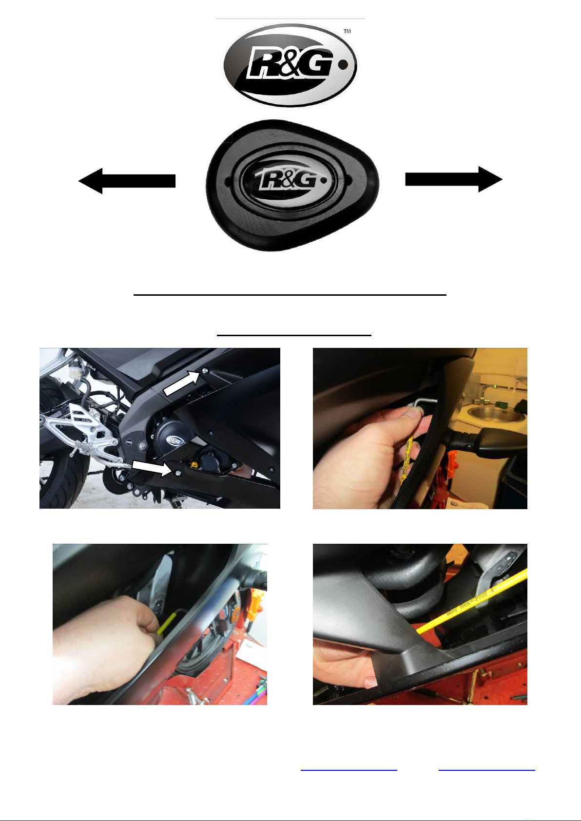
Fairing Removal
•To fit the R&G crash protectors, you will first need to remove both the LHS and RHS fairings
(instructions apply to both sides).
•Begin at the side of the bike, removing the upper and lower fairing bolts arrowed in picture
1, using a 5mm Allen key.
•Now remove the 3x bolts located on the inside face of the fairing using a 4mm Allen key, as
shown in pictures 2, 3 and 4.
•Using a small screwdriver, remove the 3x plastic push rivets located as shown in pictures 5
and 6.
•Moving to the front of the bike, remove the 2x bolts securing each fairing to the joining
panel using a 4mm Allen key, as shown in pictures 7 and 8.
•Remove the pair of plastic push rivets securing the underside of the joining panel to the
fairings, as shown in picture 9.
•Remove the bolt located on the inside face of the fairing using a 4mm Allen key, as shown in
picture 10.
•Remove the final plastic push rivet located on the inside face of the fairing, as shown in
picture 11.
•Gently pull to separate the fairing from the securing hooks, starting at the location shown in
picture 12, then carefully remove the fairing.
•Repeat steps for the opposite side of the bike.
•Now move to the LHS of the bike, and remove the front sprocket cover, using a ratchet fitted with
an 8mm socket to remove the securing bolts, as shown in picture 13.
•Remove the original lower engine mounting bolt located behind the cover, using a ratchet fitted
with a 14mm socket to hold the securing nut whilst loosening the bolt with another ratchet and
14mm socket, as shown in picture 14.
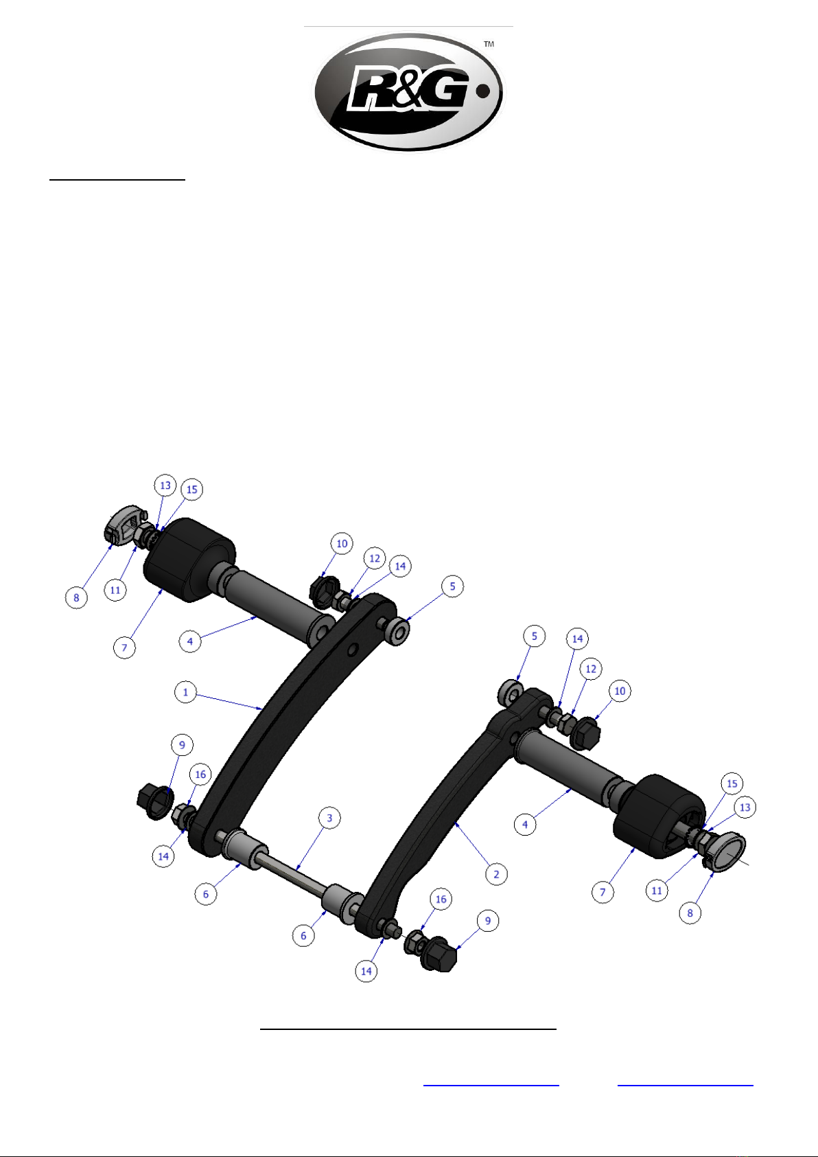
•Push the replacement engine bar (item 3 –EB095) through the vacant mounting hole as shown in
picture 15, ensuring an even protrusion of the bar on both sides.
•Slide one of the 27mm long spacers (item 6 - S1180) over the LHS exposed end of the engine bar
and gently push the bar back so that it sits flush with the surface of the spacer, as shown in picture
16. Ensure the flanged end of the spacer is pointing away from the bike.
•Staying on the LHS of the bike, remove the original upper engine mounting bolt using a ratchet
fitted with a 14mm socket, as shown in picture 17.
•Pre-assemble the LHS mounting block (item 1 - M0579) with one of the shorter bolts (item 12 –
50mm long), one of the smaller washers (item 14) and one of the 8mm long spacers (item 5 –
S1178), as shown in picture 18.