R&G Racing
Unit 1, Shelley’s Lane, East Worldham, Alton, Hampshire, GU34 3AQ
Tel: +44 (0)1420 89007 Fax: +44 (0)1420 87301 www.rg-racing.com Email: info@rg-racing.com
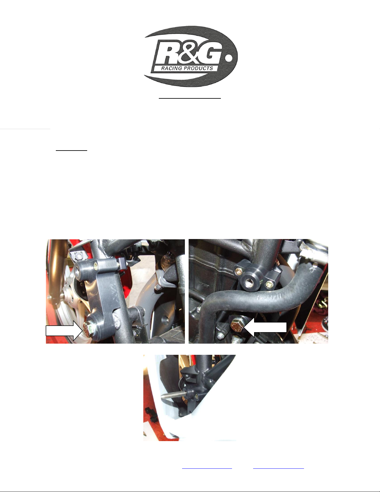
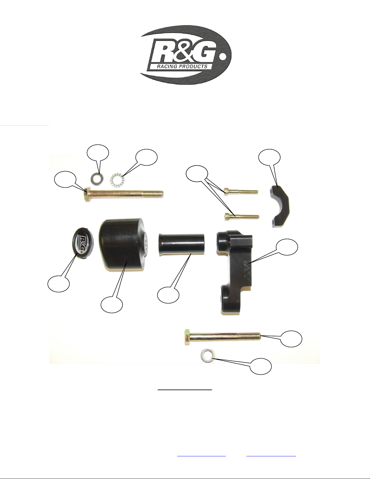
Take one of the shorter (90mm long) hex head bolts with washers and locate in the hole in
mounting block and into the frame mount as shown in picture ‘E’.
Do not tighten bolt yet.
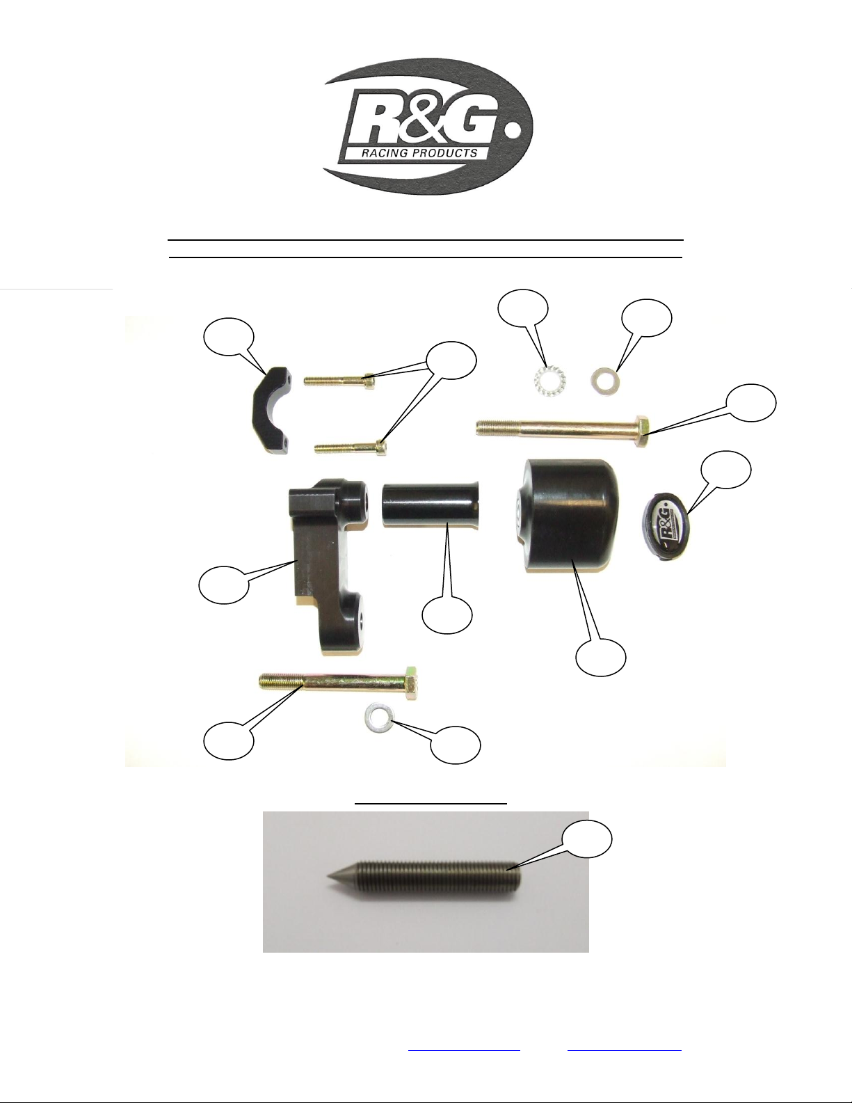
Place the frame clamp around frame and aligned with the two clamping hole and secure in position
using two of the M6x40mm long cap head bolts.
Tighten all three bolts evenly.
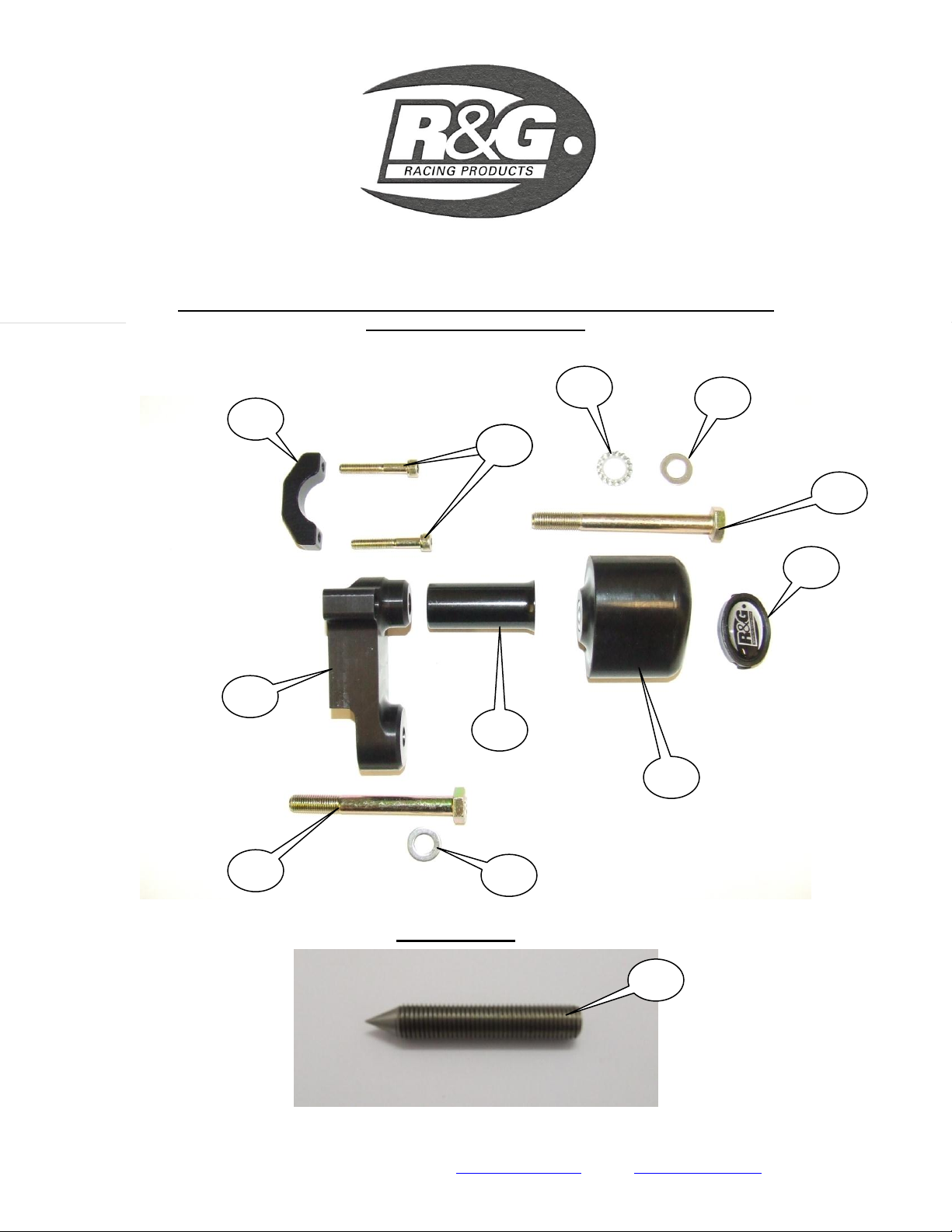
Fit the marking tool (shown in picture ‘F’) into remaining hole.
Refit the fairing ensuring the marking tool does not impede fairing.
Screw the marking tool out until it contacts inside face of fairing (as shown in picture ‘F’).
Gently push fairing into the marking tool so it leaves a mark on inside of fairing.
Remove fairing.
Drill a pilot hole in fairing (for checking position) from the inside face.
Refit fairing and ensure the pilot hole lines up with marking tool.
If happy with the position remove fairing and the marking tool.
Using the hole saw drill 28mm hole from the outside using the pilot hole as a guide, deburr hole
using a sharp knife or emery paper taking care not to mark outside of fairing.
Refit fairing (connect indicator push fittings).
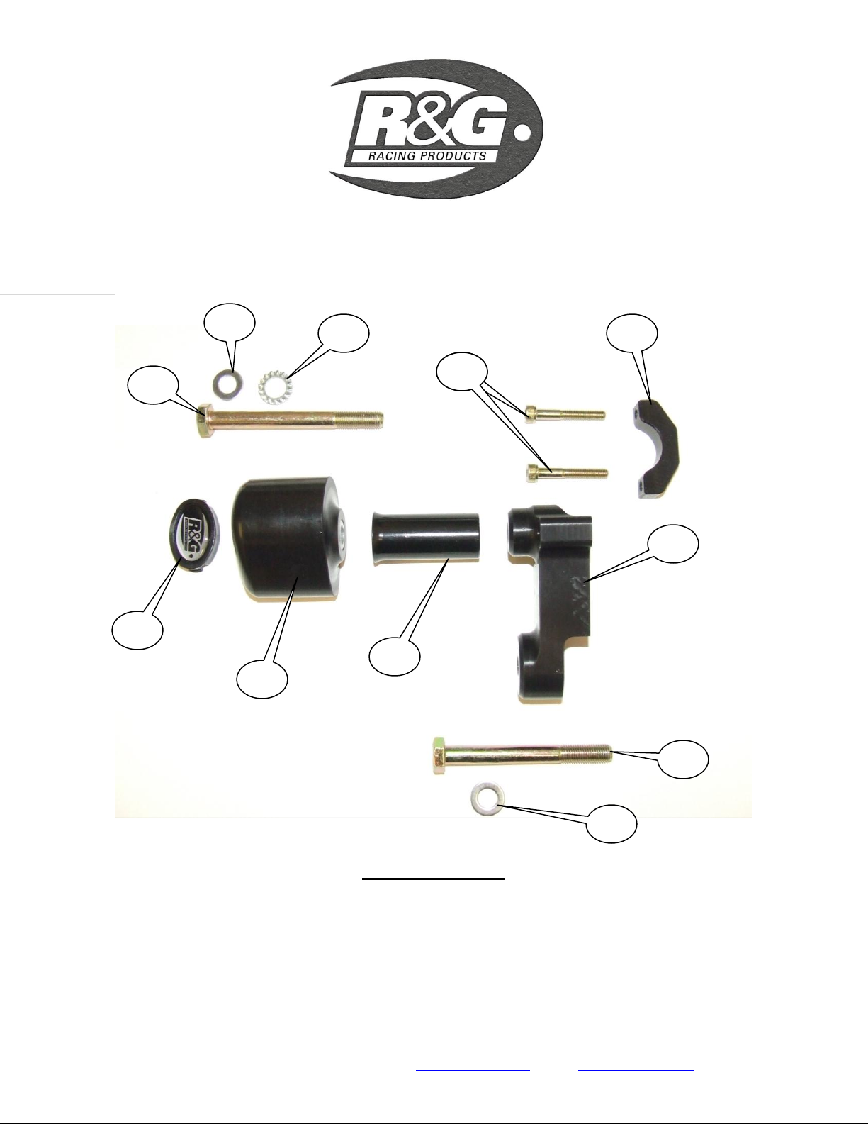
Slide one of the 10mm washers onto one the longer M10 hexagon headed bolts (100mm long) so
washer sits against head of bolt.
Slide serrated locking washer over the bolt so it sits against washer just fitted.
Next slide the bolt with washers through either crash protector so head of bolt goes into counter-
bore in bobbin.
Next slide one of the spacers over exposed end of bolt so the larger face of spacer sits against the
crash protector.
Offer this assembly through the hole in fairing (ensuring the assembly does not distort the fairing)
up to mounting block and tighten bolt until you feel some compression from inside the protector
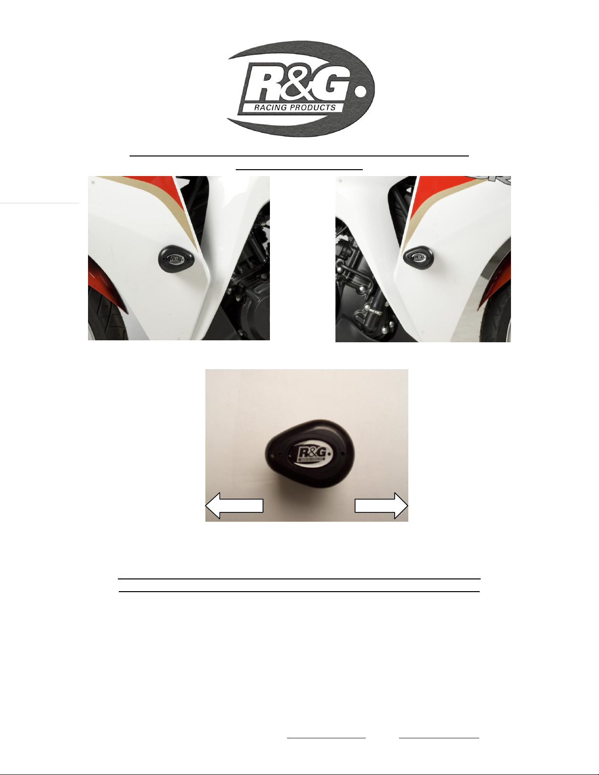
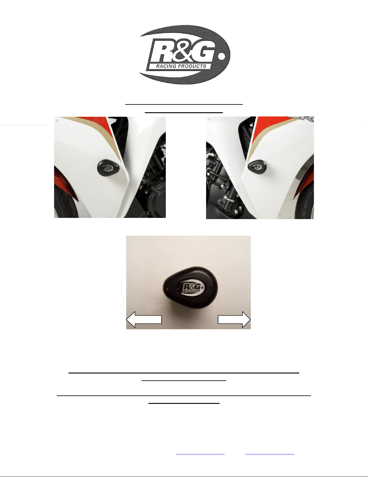
using 17mm socket and wrench. PLEASE NOTE THE CRASH PROTECTOR MUST BE
POSITIONED AS IN PICTURE ‘C’ WITH BIGGER END TOWARD FRONT OF BIKE.
Turn a little more so that you feel the compression increase slightly. Then apply a quarter turn.
Do not over tighten as damage can occur to the bike. Do not exceed 40nm of torque.
If not already fitted fit bubble sticker into recess of crash protector cap.
Fit crash protector cap into crash protector.
CONSUMER NOTICE
The catalogue description and any exhibition of samples are only broad indications of the Products and R&G may make design
changes which do not diminish their performance or visual appeal and supplying them in such state shall conform to the order. The
Buyer acknowledges no representation or warranty (other than as to title) has been given or will apply to the Products other than those
in R&G’s order or confirmation and the Buyer confirms it has chosen the Products as being of merchantable quality and suitable for
its particular purposes. Where R&G fits the Products or undertakes other services it shall exercise reasonable skill and care and rectify
any fault free of charge unless the workmanship has been disturbed. The Buyer is responsible for ensuring that the warranty on the
motorcycle is not affected by the fitting of the Products. On return of any defective Products R&G shall at its option either supply a
replacement or refund the purchase money but shall not be liable if the Products have been modified or used or maintained otherwise
than in accordance with R&G’s or manufacturer’s instructions and good engineering practice or if the defect arises from accident or
neglect. Other than identified above and subject to R&G not limiting its liability for causing death and personal injury, it shall not be
liable for indirect or consequential loss and otherwise its liability shall be limited to the amounts paid by the Buyer for the Products or
the fitting or service concerned. These terms do not affect the Buyer’s statutory rights.