R&G CP0466 Series User manual

Page 1of 9CP0466
R&G
Unit 1, Shelley’s Lane, East Worldham, Alton, Hampshire, GU34 3AQ
FITTING INSTRUCTIONS FOR CP0466 CRASH PROTECTORS
FOR BMW S1000RR ’19-
THIS KIT CONTAINS THE ITEMS PICTURED AND LABELLED BELOW.
DO NOT PROCEED UNTIL YOU ARE SURE ALL PARTS ARE PRESENT.
PLEASE NOTE THAT THE WAY THE KIT IS PACKED DOES NOT NECESSARILY REPRESENT THE WAY OF
MOUNTING TO THE BIKE
PLEASE NOTE THAT IN CASES WHERE KITS ARE PACKED WITH RUBBER WASHERS HOLDING THE COMPONENTS
ONTO THE BOLT –THE RUBBER WASHERS SHOULD BE THROWN AWAY!
THE PARTS SHOWN MAY BE REPRESENTATIVE ONLY (FOR CLARITY OF INSTRUCTIONS ONLY)
DIGITAL COPIES OF THESE INSTRUCTIONS ARE AVAILABLE TO DOWNLOAD FROM WWW.RG-RACING.COM
GENERAL TORQUE SETTINGS
M4 BOLT = 8Nm
M5 BOLT = 12Nm
M6 BOLT = 15Nm
M8 BOLT = 20Nm
M10 BOLT = 40Nm
TOOLS REQUIRED
•T50 Torx Key/Socket
•17mm Socket and Ratchet
•Torque Wrench
•Scissor Jack

Page 2of 9CP0466
R&G
Unit 1, Shelley’s Lane, East Worldham, Alton, Hampshire, GU34 3AQ
This Kit Contains:
Item 1= 2x CRASH PROTECTOR BOBBINS (B0061) W / 10mm COMPRESSION-SLEEVE (CS341)
Item 2 = 2x BOBBIN SPACERS 24mm LENGTH (S0142)
Item 3 = 2x M10 x 1.5 x 100mm HEX HEAD BOLTS
Item 4 = 2x BOBBIN CAPS W/BUBBLE STICKER AFFIXED (BC0002)
Item 5 = 2x M10 WASHERS
Item 6 = 2x SHAKE-PROOF WASHERS (LW0001)
LHS & RHS ASSEMBLY
AERO STYLE CRASH-PROTECTOR ORIENTATION
FRONT OF BIKE REAR OF BIKE

Page 4of 9CP0466
R&G
Unit 1, Shelley’s Lane, East Worldham, Alton, Hampshire, GU34 3AQ
•Before fitting the R&G crash protectors, it is advised that a scissor jack is positioned
underneath the bike at a suitable mounting point to support the weight of the engine
during fitment, as shown in picture 1. A small piece of wood should also be placed
between the jack and the mounting point to help to spread the load.
•Beginning on the right-hand side of the bike, remove the original engine mounting bolt using a T50
torx key/socket, as shown in picture 2.
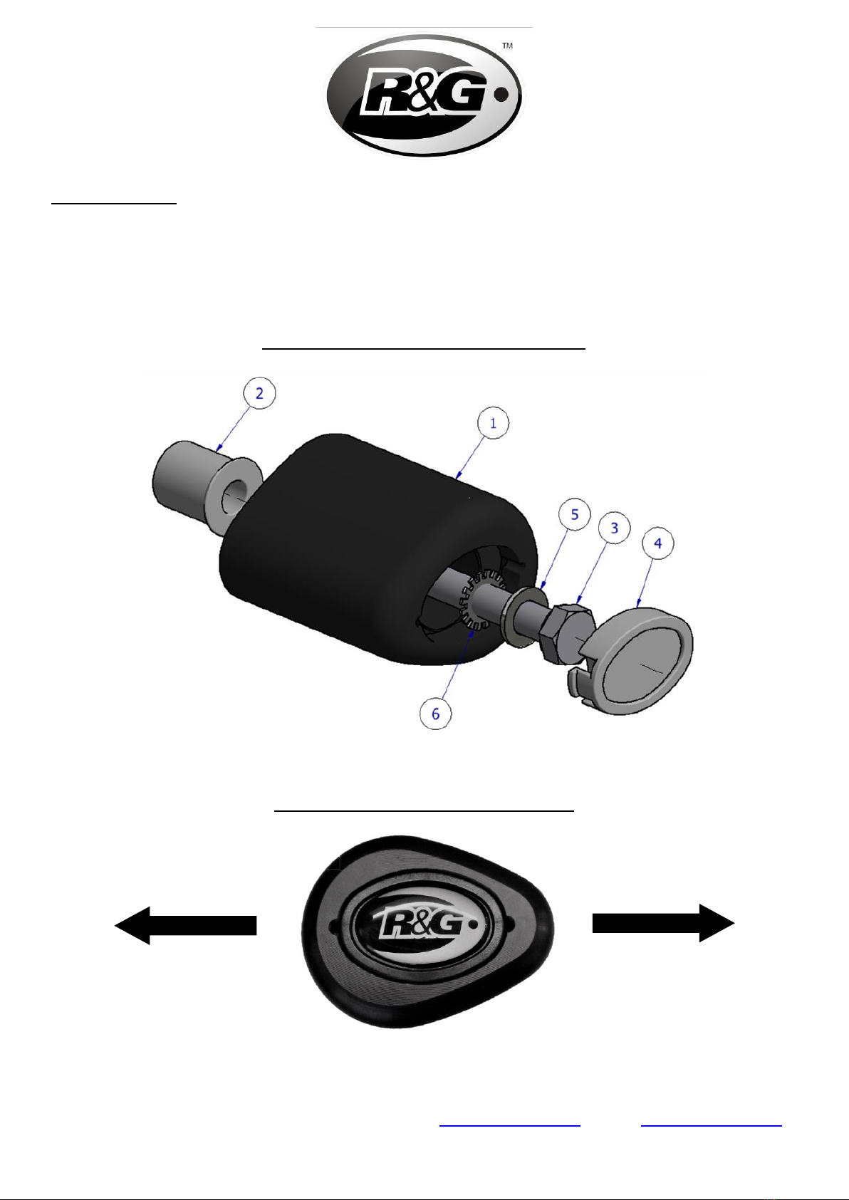
•Now assemble the first crash protector, referring to the diagram on page 2 and shown in picture 3.
First slide a washer (item 5) over one of the new hex-head bolts (item 3), followed by one of the
serrated washers (item 6). Next, slide the bolt assembly through one of the included crash bobbins
(item 1), then slide a spacer (item 2) over the exposed end of the bolt, ensuring the tapered end
sits against the bobbin’s rear face.
•Offer the pre-assembled crash protector up to the vacant engine mounting point as shown in
picture 4, then tighten the crash protector bolt using a ratchet fitted with a 17mm socket until you
feel some compression. Tighten a little more so that you feel the compression increase slightly,
then apply a quarter turn. Do not over-tighten as damage can occur to the bike. Do not exceed
40Nm of torque. PLEASE NOTE, THE CRASH PROTECTOR MUST BE POSITIONED AS IN THE
DIAGRAM ON PAGE 2, WITH THE LARGER END TOWARDS THE FRONT OF THE BIKE.
•Moving to the left-hand side of the bike, repeat the previous steps for the front engine mounting
point, as shown in picture 5.
•Finally, fit the bobbin caps (item 4) to both crash protectors, as shown in picture 6.
ISSUE 1 - 13/06/2019 (FB)
CONSUMER NOTICE
The catalogue description and any exhibition of samples are only broad indications of the Products and R&G may make design
changes which do not diminish their performance or visual appeal and supplying them in such state shall conform to the order.
The Buyer acknowledges no representation or warranty (other than as to title) has been given or will apply to the Products other
than those in R&G’s order or confirmation and the Buyer confirms it has chosen the Products as being of merchantable quality
and suitable for its particular purposes. Where R&G fits the Products or undertakes other services it shall exercise reasonable
skill and care and rectify any fault free of charge unless the workmanship has been disturbed. The Buyer is responsible for
ensuring that the warranty on the motorcycle is not affected by the fitting of the Products. On return of any defective Products
R&G shall at its option either supply a replacement or refund the purchase money but shall not be liable if the Products have
been modified or used or maintained otherwise than in accordance with R&G’s or manufacturer’s instructions and good
engineering practice or if the defect arises from accident or neglect. Other than identified above and subject to R&G not limiting
its liability for causing death and personal injury, it shall not be liable for indirect or consequential loss and otherwise its liability
shall be limited to the amounts paid by the Buyer for the Products or the fitting or service concerned. These terms do not affect
the Buyer’s statutory rights.
R&G RACING RETURNS POLICY (NON-FAULTY GOODS)
Returns must be pre-authorised (if not pre-authorised the return will be rejected). Goods may only be returned direct to us if
they were purchased direct from us (customer must prove if necessary). Otherwise to be returned to original vendor. Goods
must be in re-sellable condition, in the opinion of R&G Racing. All returns are subject to a 25% restocking and handling fee (25%
of the gross value exc. P&P –at the prevailing price at time of purchase). The customer must pay any and all carriage charges.
No returns of discontinued products, unless within 14 days of purchase. This policy does not affect your statutory rights and does
not refer to faulty goods.

Page 5of 9CP0466
R&G
Unit 1, Shelley’s Lane, East Worldham, Alton, Hampshire, GU34 3AQ
NOTICE DE MONTAGE CP0466 PROTECTIONS CRASH
FOR BMW S1000RR ’19-
LE KIT CONTIENT LES ARTICLES EXPOSES CI-DESSOUS,VERIFIER QUE TOUTES LES PIECES SOIENT PRESENTES AVANT DE
PROCEDER AU MONTAGE.
La façon dont le kit est emballé ne correspond pas forcément à la façon de monter les pièces sur la
moto
NOTEZ QUE SI LES KITS SONT EMBALLES AVEC DES RONDELLES EN CAOUTCHOUC SERVANT A TENIR LES
COMPOSANTS,CES RONDELLES DOIVENT ETRE JETEES !
LES PARTIES PRESENTÉES PEUVENT ETRE UNIQUEMENT REPRESENTATIVES (POUR LA
CLARTE DES INSTRUCTIONS UNIQUEMENT)
Notice disponible au téléchargement sur WWW.RG-RACING.COM
VALEURS DE SERRAGE RECOMMANDÉES
M4 BOULON = 8Nm
M5 BOULON = 12Nm
M6 BOULON = 15Nm
M8 BOULON = 20Nm
M10 BOULON = 40Nm
OUTILS REQUIS
•Clé Torx T50
•17mm cliquet + douille
•Clé dynamométrique
•Cric sciseau

Page 6of 9CP0466
R&G
Unit 1, Shelley’s Lane, East Worldham, Alton, Hampshire, GU34 3AQ
Le kit contient :
Article 1= 2x PROTECTIONS CRASH (B0061) W / 10mm MANCHON DE COMPRESSION (CS341)
Article 2 = 2x ENTRETOISES DE BOBINE 24mm (S0142)
Article 3 = 2x M10 x 1.5 x 100mm BOULONS
Article 4 = 2x STICKERS DE CAPUCHONS DE BOBINE (BC0002)
Article 5 = 2x M10 RONDELLES
Article 6 = 2x RONDELLES ANTI-VIBRATION (LW0001)
ASSEMBLAGE GAUCHE ET DROITE
PROTECTION CRASH LATÉRALE
AVANT MOTO ARRIÈRE MOTO

Page 7of 9CP0466
R&G
Unit 1, Shelley’s Lane, East Worldham, Alton, Hampshire, GU34 3AQ
•Avant d'installer les protections R&G, il est conseillé de placer un cric ciseau sous la moto
à un endroit approprié pour supporter le poids du moteur pendant le montage, comme
indiqué sur la photo 1. Un petit morceau de bois doit également être placé entre le cric et
le point de support pour aider à répartir la charge.
•En partant du côté droit de la moto, retirez le boulon de fixation du moteur d'origine à l'aide d'une
clé / douille T50 Torx, voir la photo 2.
•Assemblez maintenant la première protection en vous reportant au schéma de la page 2 et illustré
sur la photo 3. Commencez par faire glisser une rondelle (article 5) sur l’un des nouveaux boulons
à tête hexagonale (article 3), puis l’une des rondelles dentées (article 6). Ensuite, faites glisser le
boulon à travers l’une des bobines de protection incluses (article 1), puis faites glisser une
entretoise (article 2) sur l’extrémité exposée du boulon, en veillant à ce que son extrémité conique
repose contre la face arrière de la protection.
•Présentez la protection pré-assemblée jusqu'au point de fixation du moteur libre, comme indiqué
sur la photo 4, puis serrez le boulon de protection crash à l'aide d'un cliquet équipé d'une douille de
17 mm jusqu'à ce que vous ressentiez une certaine compression. Serrez un peu plus pour que la
compression augmente légèrement, puis appliquez un quart de tour. Ne serrez pas trop fort car la
moto pourrait être endommagée. Ne pas dépasser 40 Nm de couple. VEUILLEZ NOTER QUE LA
PROTECTION DOIT ÊTRE POSITIONNÉE COMME SUR LE SCHÉMA DE LA PAGE 2, AVEC
L’EXTRÉMITÉ LA PLUS LARGE VERS L’AVANT DE LA MOTO.
•En vous déplaçant du côté gauche de la moto, répétez les étapes précédentes pour le point de
montage du moteur avant, comme indiqué sur la photo 5.
•Enfin, installez les capuchons (article 4) sur les deux protections, comme indiqué sur la photo 6.
ISSUE 1 - 13/06/2019 (FB)

Page 8of 9CP0466
R&G
Unit 1, Shelley’s Lane, East Worldham, Alton, Hampshire, GU34 3AQ
MONTAGEANLEITUNG FÜR CP0466 STURZPADS
FÜR BMW S1000RR ’19-
ALLE KIT-TEILE SIND UNTEN ABGEBILDET UND GEKENNZEICHNET. ÜBERPRÜFEN SIE, DASS ALLE
TEILE VORHANDEN SIND, BEVOR SIE MIT DER MONTAGE BEGINNEN.
HINWEIS: DIE VERPACKUNG DER TEILE STELLT NICHT DIE REIHENFOLGE DER MONTAGE DAR.
HINWEIS FÜR KITS MIT PLASTIKUNTERLEGSCHEIBEN AN DEN SCHRAUBEN –DIESE
PLASTIKUNTERLEGSCHEIBEN WERDEN NICHT FÜR DEN EINBAU BENÖTIGT!
DIE UNTEN ABGEBILDETEN TEILE DIENEN LEDIGLICH ZUR ERKLÄRUNG
EINE DIGITALE VERSION DIESER MONTAGEANLEITUNG KANN AUF FOLGENDER SEITE HERUNTERGELADEN
WERDEN: WWW.RG-RACING.COM
ALLGEMEINE ANZUGSDREHMOMENTE
M4 SCHRAUBE = 8Nm
M5 SCHRAUBE = 12Nm
M6 SCHRAUBE = 15Nm
M8 SCHRAUBE = 20Nm
M10 SCHRAUBE = 40Nm
SIE BENÖTIGEN FOLGENDES:
•T50 Torx-Schlüssel
•17mm Steckschlüssel
•Drehmomentschlüssel
•Scherenheber

Page 9of 9CP0466
R&G
Unit 1, Shelley’s Lane, East Worldham, Alton, Hampshire, GU34 3AQ
Inhalt des Kits:
Artikel 1= 2x STURZPAD BOBBINS (B0061) W / 10mm KOMPRESSIONSHÜLSE (CS341)
Artikel 2 = 3x DISTANZHALTER 24mm LÄNGE (S0142)
Artikel 3 = 2x M10 x 1,5 x 100mm SECHSKANTSCHRAUBE
Artikel 4 = 2x STURZPAD-KAPPEN / BUBBLE-AUFKLEBER BEREITS MONTIERT (BC0002)
Artikel 5 = 2x M10 UNTERLEGSCHEIBEN
Artikel 6 = 2x ZAHNSCHEIBEN (LW0001)
•Bevor Sie die R&G Sturzpads montieren, wird empfohlen, einen Scherenheber an einem
geeigneten Montagepunkt unter das Motorrad zu stellen, um somit das Gewicht des
Motors während der Montage zu stützen –siehe Abbildung 1. Ein kleines Stück Holz
sollte auch zwischen Montagepunkt und Heber platziert werden, um die Last zu verteilen.
•Fangen Sie an der rechten Seite des Motorrades an, und entfernen Sie die original
Montageschraube für den Motor mit einem T50 Torx-Schlüssel wie in Abbildung 2 abgebildet.
•Das erste Sturzpad zusammenbauen wie in der Zeichnung auf Seite 2 und in Abbildung 3
abgebildet. Zuerst eine Unterlegscheibe (Artikel 5) gefolgt von einer Zahnscheibe (Artikel 6) über
eine der neuen Sechskantschrauben (Artikel 3) schieben. Als nächstes die Schraubeneinheit durch
ein Sturzpad (Artikel 1) führen und einen Distanzhalter (Artikel 2) über das hervorstehenden Ende
der Schraube schieben –bitte darauf achten, dass das konische Ende an der Rückseite des
Sturzpads anliegt
•Das vormontierte Sturzpad in den freien Montagepunkt für den Motor einsetzten wie in Abbildung 4
abgebildet, dann mit einem 17mm Steckschlüssel eindrehen bis Sie etwas Druck vom Inneren des
Sturzpads spüren. Noch etwas drehen, bis Sie merken, dass der Druck sich leicht erhöht, dann
noch eine Vierteldrehung anwenden. Nicht überdrehen –dies kann zu einer Beschädigung des
Motorrades führen. 40 Nm Anzugsdrehmoment nicht überschreiten! BITTE DARAUF ACHTEN,
DASS DAS STURZPAD WIE IN DER ZEICHNUNG AUF SEITE 2 POSITIONIERT IST. DAS
GRÖSSERE ENDE DES STURZPADS ZUM VORDERTEIL DES MOTORRADS GERICHTET.
•Zur linken Seite des Motorrades wechseln und die bisherigen Schritte für den vorderen
Montagepunkt des Motors wiederholen wie in Abbildung 5 abgebildet.
•Anschließend die Schutzkappen (Artikel 4) an beiden Sturzpads montieren wie in Abbildung 6
abgebildet.
AUSGABE 1 - 13/06/2019 (FB)
This manual suits for next models
2
Table of contents
Languages:
Other R&G Motorcycle Accessories manuals
Popular Motorcycle Accessories manuals by other brands

Crivit
Crivit 306979 Instructions for use

National Cycle
National Cycle ZTechnik Quantum Vstream Z2393 manual

Suzuki
Suzuki 990D0-17K10-CRB installation instructions

Gazzini
Gazzini 10030234 Instructions for use

hepco & becker
hepco & becker 5056507 00 01 manual

hepco & becker
hepco & becker 6536507 00 01 Mounting instructions