R&G LP0256BK User manual

Page 1of 19 LP0256
R&G
Unit 1, Shelley’s Lane, East Worldham, Alton, Hampshire, GU34 3AQ
FITTING INSTRUCTIONS FOR LP0256BK LICENCE PLATE BRACKET
DUCATI SCRAMBLER 1100 2018
THIS KIT CONTAINS THE ITEMS PICTURED AND LABELLED BELOW.
DO NOT PROCEED UNTIL YOU ARE SURE ALL PARTS ARE PRESENT.
Please note that the way the kit is packed does not necessarily represent the way of mounting to the bike.
THE PARTS SHOWN MAY BE REPRESENTATIVE ONLY (FOR CLARITY OF INSTRUCTIONS ONLY).
Please note that in cases where kits are packed with rubber washers holding the components onto the bolt – the
rubber washers should be thrown away!
Digital copies of these instructions are available to download from www.rg-racing.com

Page 2of 19 LP0256
R&G
Unit 1, Shelley’s Lane, East Worldham, Alton, Hampshire, GU34 3AQ
LEGEND
ITEM 1 = LICENCE PLATE BRACKET (TB0256). (x1)
ITEM 2 = M8 x 30mm BUTTON HEAD BOLT. (x2)
ITEM 3 = M8 WASHER (x2)
ITEM 4 = M8 NYLOC NUT (x2)
ITEM 5 = LICENCE PLATE ILLUMINATOR ASSEMBLY (LA0002). (x1)
ITEM 6 = LICENCE PLATE ILLUMINATOR CONNECTOR (CON0014) (x1)
ITEM 7 = 180mm LONG HEAT SHRINK. (x1)
ITEM 8 = REFLECTOR (x1)
ITEM 9 = SMALL CABLE TIES (x1)
ITEM 10 = BLACK SELF-ADHESIVE FOAM (x1)
ITEM 11 = 20 x 20mm SELF-ADHESIVE BLACK VELCRO PADS
ITEM 12 = INDICATOR CONNECTOR (CON0015) (x2)
ITEM 13 = INDICATOR ADAPTOR INSERT (I0033) (x4)

Page 3of 19 LP0256
R&G
Unit 1, Shelley’s Lane, East Worldham, Alton, Hampshire, GU34 3AQ
TOOLS REQUIRED
Comprehensive socket/spanner set.
Comprehensive Allen key set
T40 Torx bit
Small amount of adhesive
MAXIMUM TORQUE SETTINGS
M4 BOLT = 8Nm
M5 BOLT = 12Nm
M6 BOLT = 15Nm
M8 BOLT = 20Nm
M10 BOLT = 40Nm
Picture 1 Picture 2
Picture 3 Picture 4

Page 4of 19 LP0256
R&G
Unit 1, Shelley’s Lane, East Worldham, Alton, Hampshire, GU34 3AQ
Picture 5 Picture 6
Picture 7 Picture 8
Picture 9 Picture 10

Page 5of 19 LP0256
R&G
Unit 1, Shelley’s Lane, East Worldham, Alton, Hampshire, GU34 3AQ
Picture 11 Picture 12
Picture 13 Picture 14
Picture 15
Picture 16

Page 6of 19 LP0256
R&G
Unit 1, Shelley’s Lane, East Worldham, Alton, Hampshire, GU34 3AQ
Picture 17 Picture 18
Picture 19 Picture 20
Picture 21 Picture 22
Original Indicator Mount

Page 7of 19 LP0256
R&G
Unit 1, Shelley’s Lane, East Worldham, Alton, Hampshire, GU34 3AQ
Picture 23 Picture 24
Picture 25 Picture 26
FITTING INSTRUCTIONS
Remove the seat.
Undo the T40 Torx bolt which secures the RH exhaust to the exhaust mount (shown in Picture 1), and carefully
pull the exhaust silencer out of the exhaust pipe.
Repeat the previous step on the LH exhaust.
Remove the two bolts securing the brake light assembly (shown in Picture 2), and carefully pull the brake light
assembly rearwards to remove it from the mounting plate.
The brake light mounting plate can now be removed, by undoing the three bolts shown in Picture 3.
Undo the two bolts securing the exhaust mount (Picture 4) and remove the mount.
Remove the two lower bolts securing the upper rear body panel (shown in Picture 5), ensuring that the spacers
are put to one side ready for re-installation later.
Remove the two upper bolts (shown in Picture 6) securing the upper rear body panel, and carefully remove the
panel (shown in Picture 7).
Remove the four bolts shown in Picture 8 and be sure to support the plastic undertray to prevent damaging the
indicator wires.

Page 8of 19 LP0256
R&G
Unit 1, Shelley’s Lane, East Worldham, Alton, Hampshire, GU34 3AQ
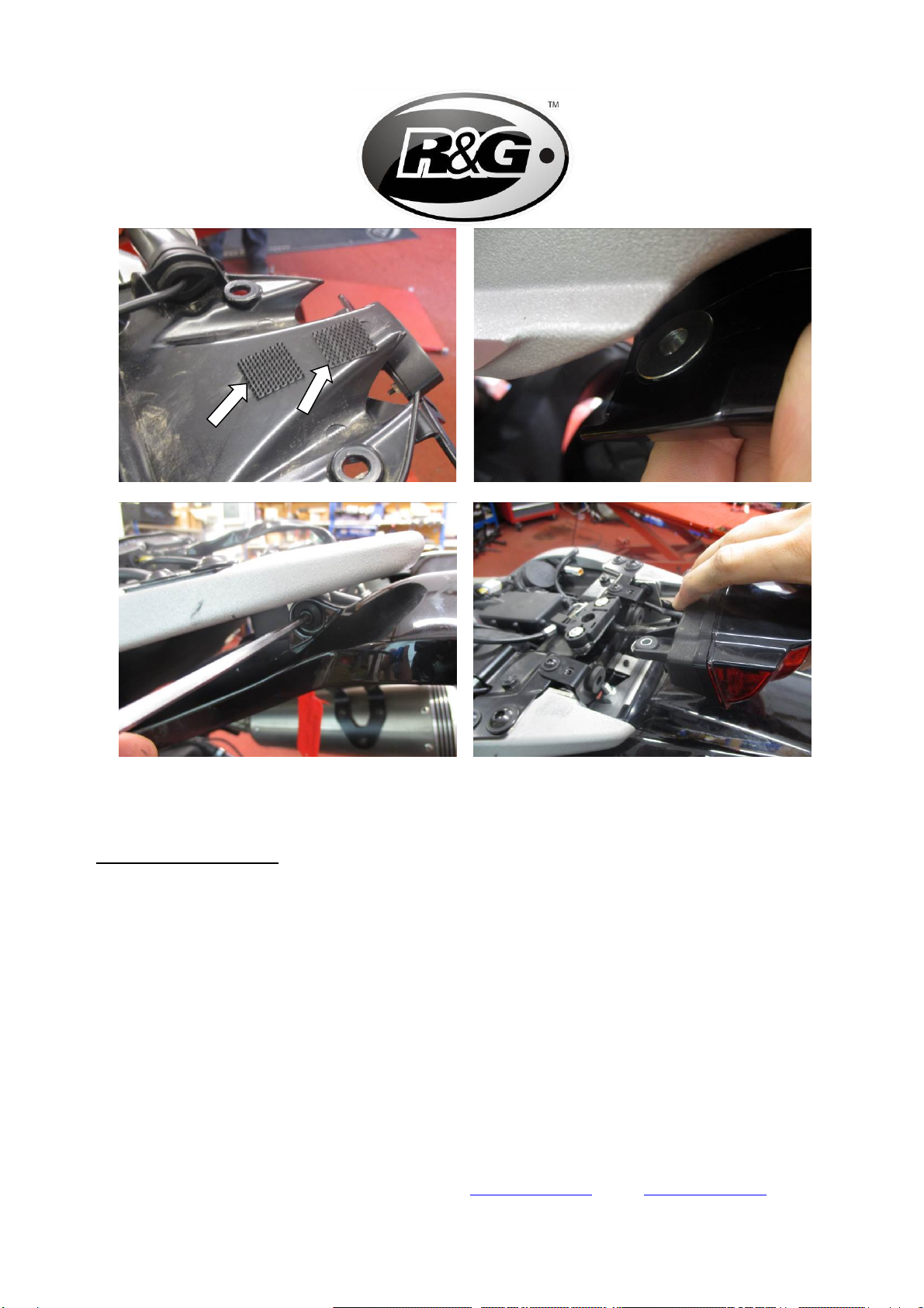
Trace the licence plate illuminator wire back to its connector and unplug it (shown in Picture 9 and Picture 10).
Remove the two bolts securing the licence plate subframe (Picture 11) and ensure that it is being supported.
Then carefully remove the subframe from the bike, taking care not to pull or damage any wires.
Cut the 200mm long self-adhesive foam into two 100mm long strips and stick them to the top of the tail tidy
(Picture 12).
Feed the tail tidy through the plastic undertray (as shown in Picture 13) and using the original bolts, secure the
tail tidy in place (Picture 14).
Re-fit the brake light mounting plate, ensuring that the bottom tab is tucked underneath the tail tidy (Picture 15).
NOTE – THE TAIL TIDY MAY NEED TO BE ANGLED SLIGHLY IN ORDER TO RE-FIT THE MOUNT
PLATE.
Secure the brake light mounting plate back in place by using the three original bolts, with the bottom bolt
tightened from underneath (Picture 16).
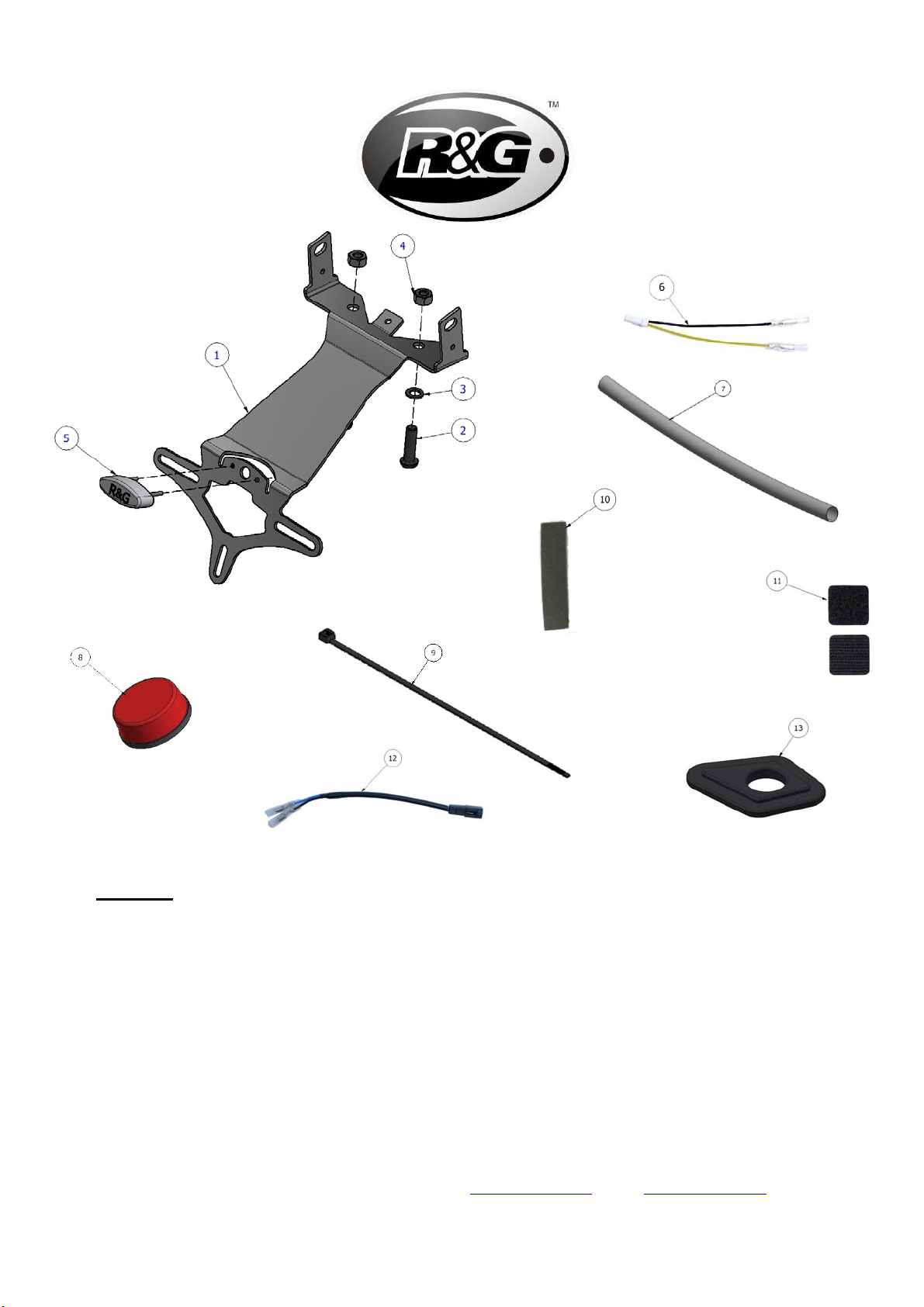
Using the two M8 x 30mm button head bolts provided (ITEM 2), along with washers (ITEM 3) and Nyloc nuts
(ITEM 4), secure the exhaust mounting plate to the tail tidy.
Mount the licence plate illuminator assembly (ITEM 5) to the tail tidy (ITEM 1), using the bolts, nuts and
washers provided, please note you will have to fit the light shroud and use a small amount of adhesive to hold it
in position.
Fit the provided length of heat shrink (ITEM 7) to protect the licence plate illuminator wires.
Re-route the licence plate illuminator wiring, following the original wiring layout, using the supplied cable tie
(ITEM 9) to neatly route the wires.
Connect the licence plate illuminator connector (ITEM 6) to the wiring loom (Picture 19) and connect the two
bullet connectors to the R&G licence plate illuminator.
Check operation of all lights at this stage (if illumination fails, swap the bullet connectors around).
If fitting mini indicators (Ignore this section if using OEM Indicators)
Trace the original indicator wires back to the connectors, and disconnect them, noting which is the LH and RH.
Carefully remove the original indicators (noting the routing of the wiring), by gently pulling them out of the
plastic undertray.
Place two indicator adaptor inserts (ITEM 13), either side of the original indicator mount opening and feed the
mini indicator wires through the two adaptors.
Secure the mini indicator in place using the M8 nut provided with the mini indicator kit (shown in Picture 21).
Connect the two indicator connectors (ITEM 12) to the original loom and connect the two bullet connectors to
the mini indicators.
Check operation of all lights at this stage (if illumination fails, swap the bullet connectors around).
NOTE: 1 x set of RGR0001 resistors (available separately) may be required to achieve the correct flash
rate.
Stick two Velcro pads to the upper rear body panel and plastic undertray, before re-fitting the upper rear body
panel (Picture 22 and Picture 23).
Re-fit the upper rear body panel, ensuring that the spacers are re-installed for the bottom two mounts (Picture 24
and Picture 25).
Carefully re-fit the brake light assembly, and secure in place using the two original bolts.
Refit the seat as original and licence plate (it may require drilling).
Please check the operation of all lights before riding the motorcycle.

Page 9of 19 LP0256
R&G
Unit 1, Shelley’s Lane, East Worldham, Alton, Hampshire, GU34 3AQ
IMPORTANT: IF FITTING A FULL-SIZE LICENCE PLATE AND PLACING IT FAR DOWN ON
THE LICENCE PLATE HANGER, THERE IS A SMALL CHANCE OF THE LICENCE PLATE
HITTING THE BACK WHEEL UNDER HEAVY LOAD AND OVER LARGE BUMPS IN THE ROAD.
IT IS YOUR RESPONSIBILITY TO CHECK FOR THIS POSSIBILITY AND TAKE AVOIDING
ACTION. FAILURE TO CHECK THIS COULD RESULT IN SERIOUS INJURY.
Depending on local laws, attach enclosed reflector (item 8) in an appropriate location
ISSUE 1 26/09/2018 (LF)
CONSUMER NOTICE
The catalogue description and any exhibition of samples are only broad indications of the Products and R&G may make design changes which do not
diminish their performance or visual appeal and supplying them in such state shall conform to the order. The Buyer acknowledges no representation or
warranty (other than as to title) has been given or will apply to the Products other than those in R&G’s order or confirmation and the Buyer confirms it
has chosen the Products as being of merchantable quality and suitable for its particular purposes. Where R&G fits the Products or undertakes other
services it shall exercise reasonable skill and care and rectify any fault free of charge unless the workmanship has been disturbed. The Buyer is
responsible for ensuring that the warranty on the motorcycle is not affected by the fitting of the Products. On return of any defective Products R&G
shall at its option either supply a replacement or refund the purchase money but shall not be liable if the Products have been modified or used or
maintained otherwise than in accordance with R&G’s or manufacturer’s instructions and good engineering practice or if the defect arises from accident
or neglect. Other than identified above and subject to R&G not limiting its liability for causing death and personal injury, it shall not be liable for
indirect or consequential loss and otherwise its liability shall be limited to the amounts paid by the Buyer for the Products or the fitting or service
concerned. These terms do not affect the Buyer’s statutory rights.
R&G RETURNS POLICY (NON-FAULTY GOODS)
Returns must be pre-authorised (if not pre-authorised the return will be rejected). Goods may only be returned direct to us if they were purchased direct
from us (customer must prove if necessary). Otherwise to be returned to original vendor. Goods must be in re-sellable condition, in the opinion of
R&G. All returns are subject to a 25% restocking and handling fee (25% of the gross value exc. P&P – at the prevailing price at time of purchase). The
customer must pay any and all carriage charges. No returns of discontinued products, unless within 14 days of purchase. This policy does not affect
your statutory rights and does not refer to faulty goods.

Page 10 of 19 LP0256
R&G
Unit 1, Shelley’s Lane, East Worldham, Alton, Hampshire, GU34 3AQ
NOTICE DE MONTAGE POUR LP0256BK SUPPORT DE PLAQUE
DUCATI SCRAMBLER 1100 2018
Le kit contient les articles exposés ci-dessous, vérifier que toutes les pièces soient présentes avant de
procéder au montage.
La façon dont le kit est emballé ne correspond pas forcément à la façon de monter les pièces sur la moto.
LES PARTIES PRESENTEES PEUVENT ETRE UNIQUEMENT REPRESENTATIVES (POUR LA
CLARTÉ DES INSTRUCTIONS UNIQUEMENT).
Notez que si les kits sont emballés avec des rondelles en caoutchouc servant à tenir les composants, ces rondelles
doivent être jetées !
Notice disponible au téléchargement sur www.rg-racing.com

Page 11 of 19 LP0256
R&G
Unit 1, Shelley’s Lane, East Worldham, Alton, Hampshire, GU34 3AQ
LÉGENDE
ARTICLE 1 = SUPPORT DE PLAQUE (TB0256). (x1)
ARTICLE 2 = M8 x 30mm BOULON (x2)
ARTICLE 3 = M8 RONDELLE (x2)
ARTICLE 4 = M8 ÉCROU (x2)
ARTICLE 5 = ASSEMBLAGE FEU DE PLAQUE (LA0002). (x1)
ARTICLE 6 = CONNECTEUR DE FEU DE PLAQUE (CON0014) (x1)
ARTICLE 7 = 180mm LONGEUR DE MANCHON THERMO RÉTRACTABLE (x1)
ARTICLE 8 = RÉFLECTEUR (x1)
ARTICLE 9 = COLLIERS DE SERRAGE (x1)
ARTICLE 10 = MOUSSE AUTOCOLLANTE (x1)
ARTICLE 11 = 20 x 20mm PADS EN VELCRO NOIR AUTOCOLLANT
ARTICLE 12 = CONNECTEUR DE CLIGNOTANT (CON0015) (x2)
ARTICLE 13 = INSERT D’ADAPTATEUR DE CLIGNOTANT (I0033) (x4)

Page 12 of 19 LP0256
R&G
Unit 1, Shelley’s Lane, East Worldham, Alton, Hampshire, GU34 3AQ
OUTILS REQUIS
Jeu complet de douilles / clés.
Jeu de clés Allen
Clé Torx T40
Un peu d’adhésif
VALEURSDESERRAGERECOMMANDÉES
M4BOULON=8Nm
M5BOULON=12Nm
M6BOULON=15Nm
M8BOULON=20Nm
M10BOULON=40Nm
NOTICE DE MONTAGE
Enlever le siège.
Enlever le boulon T40 Torx qui fixe l’échappement droit au support d’échappement (voir Photo 1), puis tirer le
silencieux d’échappement en dehors du pot.
Répéter l’étape précédente sur l’échappement gauche.
Enlever les 2 boulons qui fixent l’assemblage de feu stop (voir Photo 2), puis tirer l’ensemble de feu stop vers
l’arrière pour l’enlever de la plaque de montage
La plaque de montage du feu stop peut maintenant être enlevée, en enlevant les 3 boulons indiqués sur la Photo
3.
Enlever les 2 boulons qui fixent le support d’échappement (Photo 4) puis enlever le support.
Enlever les 2 boulons inférieurs qui fixent le panneau de carénage supérieur arrière (voir Photo 5), en veillant à
ce que les entretoises soient mises de côté pour être réinstallées plus tard.
Enlever les 2 boulons supérieurs (voir Photo 6) qui fixent le panneau de carénage arrière, puis enlever le panneau
(voir Photo 7).
Enlever les 4 boulons indiqués sur la Photo 8 puis supportez le sous plateau pour éviter d’abimer les fils de
clignotant.
Tracer le fil de feu de plaque jusqu’à son connecteur puis débranchez le (voir Photo 9 et Photo 10).
Enlever les 2 boulons qui fixent le sous cadre de plaque (Photo 11) en faisant attention à le supporter.
Ensuite, enlever le sous-cadre de la moto, en faisant attention à ne pas tirer sur les fils ni à les abîmer.
Couper la mousse autocollante de 200mm en 2 pièces de 100mm puis collez les sur le haut du support de plaque
(Photo 12).
Passer le support de plaque dans le sous plateau en plastique (voir Photo 13) puis fixer le support de plaque à
l’aide des boulons d’origine (Photo 14).

Page 13 of 19 LP0256
R&G
Unit 1, Shelley’s Lane, East Worldham, Alton, Hampshire, GU34 3AQ
Remonter la plaque de montage du feu stop, en
veillant à ce que l’onglet du bas soit rangé sous le support de plaque (Photo 15). NOTE – LE SUPPORT DE
PLAQUE DOIT ÊTRE LÉGÈREMENT INCLINÉ POUR QUE VOUS PUISSIEZ Y RÉINSTALLER LA
PLAQUE DE SUPPORT.
Fixer la plaque de montage de feu stop en place, en utilisant les 3 boulons d’origine, avec le boulon du bas serré
pas dessous (Photo 16).
Utiliser les 2 boulons M8 x 30mm fournis (ARTICLE 2), avec des rondelles (ARTICLE 3) et écrous (ARTICLE
4), fixer la plaque de montage de l’échappement sur le support de plaque.
Monter l’assemblage de feu de plaque (ARTICLE 5) sur le support de plaque (ARTICLE 1), en utilisant les
boulons, écrous et rondelles fournis, notez que vous devrez monter le linceul de feu et utiliser un peu d’adhésif
pour fixer la position.
Appliquer le manchon thermos rétractable (ARTICLE 7) sur le fils du feu de plaque afin de les protéger.
Route à nouveau les fils de feu de plaque, en suivant le schéma du câblage d’origine, et en utilisant le collier de
serrage fourni (ARTICLE 9) pour router les fils.
Connecter le connecteur de feu de plaque (ARTICLE 6) sur le faisceau de fils (Photo 19) puis connecter les 2
connecteurs au feu de plaque R&G.
Vérifiez que tous les feux fonctionnent à ce stade (Si l’éclairage échoue, tournez les connecteurs).
Si vous montez les mini clignotants (Ignorer cette partie si vous réinstallez les clignotants d’origine)
Tracer les fils de clignotant d’origine jusqu’aux connecteurs, puis déconnectez les en notant chaque côté gauche
et droit.
Enlever délicatement les clignotants d’origine (en notant le routage du fil), en les tirant du sous plateau en
plastique.
Placer 2 inserts d’adaptateur de clignotant (ARTICLE 13), de chaque côté du support de clignotant d’origine en
ouvrant et en passant les fils dans les 2 adaptateurs.
Fixer le mini clignotant en place en utilisant l’écrou M8 founi avec le kit de mini clignotant (voir Photo 21).
Connecter les 2 connecteurs de clignotant (ARTICLE 12) sur le faisceau d’origine puis connecter les 2
connecteurs sur les mini clignotants.
Vérifiez que tous les feux fonctionnent à ce stade (Si l’éclairage échoue, tournez les connecteurs).
NOTE : 1 x set de résistances RGR0001 (disponible séparément) peuvent être nécessaires pour obtenir le
bon niveau d’éclairage.
Coller 2 Velcro sur le panneau de carénage arrière supérieur et le sous plateau, avant de remonter le panneau de
carénage arrière supérieur (Photo 22 et Photo 23).
Remonter le panneau de carénage arrière supérieur, en veillant à ce que les entretoises soient réinstallées sur les
2 supports du bas (Photo 24 et Photo 25).
Remonter l’assemblage de feu stop puis fixez le en place en utilisant les 2 boulons d’origine.
Remonter le siège comme à l’origine ainsi que la plaque d’immatriculation, peut nécessiter un perçage.
Tester l’ensemble des feux avant de prendre la route.
IMPORTANT : Si vous installez une grosse plaque, il y a un risque que la plaque entre en
contact avec la roue arrière en cas de choc sur la route (bosse, grosse charge etc..). Il est de
votre responsabilité de vérifier que cela ne puisse pas se produire. Ne pas effectuer ces
vérifications peut entrainer des dommages ainsi que des blessures graves pour le pilote.
Selon les lois locales, attacher le réflecteur rouge (article 8) à l’endroit approprié.
ISSUE 1 26/09/2018 (LF)

Page 14 of 19 LP0256
R&G
Unit 1, Shelley’s Lane, East Worldham, Alton, Hampshire, GU34 3AQ
CONSUMER NOTICE
The catalogue description and any exhibition of samples are only broad indications of the Products and R&G may make design changes which do not
diminish their performance or visual appeal and supplying them in such state shall conform to the order. The Buyer acknowledges no representation or
warranty (other than as to title) has been given or will apply to the Products other than those in R&G’s order or confirmation and the Buyer confirms it
has chosen the Products as being of merchantable quality and suitable for its particular purposes. Where R&G fits the Products or undertakes other
services it shall exercise reasonable skill and care and rectify any fault free of charge unless the workmanship has been disturbed. The Buyer is
responsible for ensuring that the warranty on the motorcycle is not affected by the fitting of the Products. On return of any defective Products R&G
shall at its option either supply a replacement or refund the purchase money but shall not be liable if the Products have been modified or used or
maintained otherwise than in accordance with R&G’s or manufacturer’s instructions and good engineering practice or if the defect arises from accident
or neglect. Other than identified above and subject to R&G not limiting its liability for causing death and personal injury, it shall not be liable for
indirect or consequential loss and otherwise its liability shall be limited to the amounts paid by the Buyer for the Products or the fitting or service
concerned. These terms do not affect the Buyer’s statutory rights.
R&G RETURNS POLICY (NON-FAULTY GOODS)
Returns must be pre-authorised (if not pre-authorised the return will be rejected). Goods may only be returned direct to us if they were purchased direct
from us (customer must prove if necessary). Otherwise to be returned to original vendor. Goods must be in re-sellable condition, in the opinion of
R&G. All returns are subject to a 25% restocking and handling fee (25% of the gross value exc. P&P – at the prevailing price at time of purchase). The
customer must pay any and all carriage charges. No returns of discontinued products, unless within 14 days of purchase. This policy does not affect
your statutory rights and does not refer to faulty goods.

Page 15 of 19 LP0256
R&G
Unit 1, Shelley’s Lane, East Worldham, Alton, Hampshire, GU34 3AQ
MONTAGEANLEITUNG FÜR LP0256BK KENNZEICHENHALTER
DUCATI SCRAMBLER 1100 2018
ALLE KIT-TEILE SIND UNTEN ABGEBILDET UND GEKENNZEICHNET. BEVOR SIE MIT DER
MONTAGE BEGINNEN, ÜBERPRÜFEN SIE, DASS ALLE TEILE VORHANDEN SIND.
Hinweis: Die Verpackung der Teile stellt nicht die Reihenfolge der Montage dar.
DIE UNTEN ABGEBILDETEN TEILE DIENEN LEDIGLICH ZUR ERKLÄRUNG
Hinweis für Kits mit Plastikunterlegscheiben an den Schrauben – Diese Plastikunterlegscheiben werden
nicht für den Einbau benötigt!
Eine digitale Version dieser Montageanleitung kann auf folgender Seite heruntergeladen werden: www.rg-
racing.com

Page 16 of 19 LP0256
R&G
Unit 1, Shelley’s Lane, East Worldham, Alton, Hampshire, GU34 3AQ
LIEFERUMFANG
ARTIKEL 1 = KENNZEICHENHALTER (TB0256) (x1)
ARTIKEL 2 = M8 x 30mm INBUSSCHRAUBE (x2)
ARTIKEL 3 = M8 UNTERLEGSCHEIBE (x2)
ARTIKEL 4 = M8 SELBSTSICHERNDE MUTTER (x2)
ARTIKEL 5 = KENNZEICHENBELEUCHTUNG (LA0002) (x1)
ARTIKEL 6 = VERBINDUNG FÜR DIE KENNZEICHENBELEUCHTUNG (CON0014) (x1)
ARTIKEL 7 = 180mm SCHRUMPFSCHLAUCH (x1)
ARTIKEL 8 = RÜCKSTRAHLER (x1)
ARTIKEL 9 = KLEINE KABELBINDER (x1)
ARTIKEL 10 = SELBSTKLEBENDER SCHAUMSTOFF (SCHWARZ) (x1)
ARTIKEL 11 = 20 x 20mm SELBSTKLEBENDE SCHWARZE KLETTBAND-PADS
ARTIKEL 12 = VERBINDUNG FÜR DIE BLINKER (CON0015) (x2)
ARTIKEL 13 = ADAPTER-EINSATZ FÜR DIE BLINKER (I0033) (x4)

Page 17 of 19 LP0256
R&G
Unit 1, Shelley’s Lane, East Worldham, Alton, Hampshire, GU34 3AQ
SIE BENÖTIGEN FOLGENDES WERKZEUG
Steckschlüsselsatz
Satz Inbusschlüssel
T40 Torx-Einsatz
etwas Sekundenkleber
MAX.ANZUGSDREHMOMENTE:
M4 SCHRAUBE = 8 NM
M5 SCHRAUBE = 12NM
M6 SCHRAUBE = 15NM
M8 SCHRAUBE = 20NM
M10 SCHRAUBE = 40NM
MONTAGEANLEITUNG
Entfernen Sie den Sitz.
Lösen Sie die T40 Torx-Schraube, die den rechten Auspuff an der Auspuffhalterung befestigt (siehe Abbildung
1), und ziehen Sie den Schalldämpfer vom Auspuffrohr.
Wiederholen Sie diesen Schritt mit dem linken Auspuff.
Entfernen Sie die zwei Schrauben, die die Bremslicht-Einheit befestigen (siehe Abbildung 2), und ziehen Sie die
Einheit nach hinten, um sie von der Montageplatte zu entfernen.
Die Montageplatte für das Bremslicht kann jetzt entfernt werden, indem Sie die drei Schrauben, die in
Abbildung 3 abgebildet sind, lösen.
Lösen Sie die zwei Schrauben, die die Auspuffhalterung befestigen (Abbildung 4) und entfernen Sie die
Halterung.
Entfernen Sie die zwei unteren Schrauben, die die obere Heckverkleidung (siehe Abbildung 5) befestigen – bitte
darauf achten, dass beide Distanzhalter zur Seite gelegt werden, diese werden für den späteren Einbau benötigt.
Entfernen Sie die zwei oberen Schrauben (siehe Abbildung 6), die die obere Heckverkleidung befestigen, und
entfernen Sie die Verkleidung (siehe Abbildung 7).
Entfernen Sie die vier Schrauben, die in Abbildung 8 abgebildet sind – stützen Sie dabei die untere Abdeckung,
um zu verhindern, dass die Kabel für die Blinker beschädigt werden.
Trennen Sie den Stecker für die Kennzeichenbeleuchtung (siehe Abbildungen 9 und 10).
Entfernen Sie die zwei Schrauben, die den Hilfsrahmen für den Kennzeichenhalter befestigen (Abbildung 11) –
den Hilfsrahmen dabei stützen.
Entfernen Sie den Hilfsrahmen vom Motorrad – bitte darauf achten, dass die Kabel nicht beschädigt oder
gezogen werden.
Den 200mm selbstklebenden-Schaumstoff in zwei 100mm lange Streifen schneiden, und kleben Sie sie oben auf
dem Kennzeichenhalter (Abbildung 12).
Führen Sie den Kennzeichenhalter durch die untere Abdeckung (wie in Abbildung 13 abgebildet), und den
Kennzeichenhalter mit den Originalschrauben in Position befestigen (Abbildung 14).

Page 18 of 19 LP0256
R&G
Unit 1, Shelley’s Lane, East Worldham, Alton, Hampshire, GU34 3AQ
Montieren Sie die Montageplatte für das
Bremslicht wieder – bitte darauf achten, dass die untere Lasche unter dem Kennzeichenhalter verstaut ist
(Abbildung 15). HINWEIS – DER KENNZEICHENHALTER MUSS EVENTUELL ETWAS SCHRÄG
ANGEWINKELT WERDEN, UM DIE MONTAGEPLATTE WIEDER ANBAUEN ZU KÖNNEN.
Sichern Sie die Montageplatte für das Rücklicht wieder in Position mit den drei Originalschrauben – die untere
Schraube wird von unten festgezogen (Abbildung 16).
Benutzen Sie die zwei M8 x 30mm Inbusschrauben vom Kit (Artikel 2), sowie die Unterlegscheiben (Artikel 3)
und selbstsichernde Muttern (Artikel 4), um die Auspuff-Montageplatte am Kennzeichenhalter zu befestigen.
Die Kennzeichenbeleuchtung-Einheit (Artikel 5) am Kennzeichenhalter (Artikel 1) befestigen mit den
Schrauben, Muttern und Unterlegscheiben vom Kit. Hinweis: etwas Sekundenkleber wird benötigt, um die
Lichtabdeckung in Position zu befestigen.
Den Schrumpfschlauch vom Kit (Artikel 7) anbringen, um die Kabel für die Kennzeichenbeleuchtung zu
schützen.
Die Verkabelung der Kennzeichenbeleuchtung neu verlegen, unter Berücksichtigung der original Verlegung –
die mitgelieferten Kabelbinder (Artikel 9) verwenden, um die Kabel ordentlich zu verstauen.
Verbinden Sie den Verbinder für die Kennzeichenbeleuchtung (Artikel 6) mit dem Kabelbaum (Abbildung 19)
und verbinden Sie die zwei Kabelverbinder mit der R&G Kennzeichenbeleuchtung.
Überprüfen Sie nun die Funktion der Beleuchtung (Falls die Beleuchtung nicht funktionieren sollte, tauschen Sie
die Kabelverbinder untereinander).
Wenn Sie R&G Miniblinker verwenden: (Diese Schritte überspringen, wenn Sie die original Blinker verwenden)
Trennen Sie die Verbinder für die original Blinkerkabel – bitte die entsprechende Seite (rechts/links) notieren.
Entfernen Sie die original Blinker (die Verlegung der Kabel notieren), indem Sie sie vorsichtig aus der unteren
Abdeckung ziehen.
Die zwei Adapter-Einsätze für die Blinker (Artikel 13) an beiden Seiten der original Öffnung für die
Blinkerhalterung anbringen und die Kabel für die Miniblinker durch die zwei Adapter führen.
Die Miniblinker in Position befestigen mit der M8 Mutter, die im Miniblinker-Kit enthalten ist (siehe Abbildung
21).
Verbinden Sie die zwei Verbindungen für die Blinker (Artikel 12) mit dem original Kabelbaum und verbinden
Sie die zwei Kabelverbinder mit den Miniblinkern.
Überprüfen Sie nun die Funktion der Beleuchtung (Falls die Beleuchtung nicht funktionieren sollte, tauschen Sie
die Kabelverbinder untereinander). HINWEIS: 1 x Satz RGR0001 Widerstände (separat erhältlich) wird
eventuell benötigt, um die richtige Blitzgeschwindigkeit zu bekommen.
Kleben Sie die zwei Klettband-Pads an der oberen Heckverkleidung und der unteren Abdeckung, bevor Sie die
obere Heckverkleidung wieder montieren (siehe Abbildungen 22 und 23).
Montieren Sie die untere Heckverkleidung wieder – bitte darauf achten, dass die Distanzhalter wieder an den
zwei unteren Halterungen montiert werden (Abbildung 24 und Abbildung 25).
Montieren Sie die Bremslicht-Einheit wieder und mit befestigen Sie sie mit den zwei original Schrauben.
Montieren Sie den Sitz wie ursprünglich wieder sowie das amtliche Kennzeichen (Bohrungen im Kennzeichen
evtl. notwendig).
Überprüfen Sie die Funktion der kompletten Beleuchtung (Blinker und Kennzeichenhalterbeleuchtung) nochmal
vor Gebrauch des Fahrzeuges.

Page 19 of 19 LP0256
R&G
Unit 1, Shelley’s Lane, East Worldham, Alton, Hampshire, GU34 3AQ
WICHTIG: WENN EIN GROSSES KENNZEICHEN ZU WEIT NACH UNTEN MONTIERT WIRD,
BESTEHT BEI SCHWEREM LAST ODER DURCH GROSSE BODENWELLEN EIN GERINGES
RISIKO, DASS DAS KENNZEICHEN AN DAS HINTERRAD STOSSEN KANN. ES LIEGT IN IHRER
VERANTWORTUNG DIES ZU ÜBERPRÜFEN UND, WENN NOTWENDIG, VORZUBEUGENDE
MASSNAHMEN ZU ERGREIFEN. DIE NICHTBEACHTUNG DIESES SICHERHEITSHINWEIS
KANN ZU SCHWEREN VERLETZUNGEN FÜHREN.
Entsprechend der gesetzlichen Vorschriften, den mitgelieferten Rückstrahler (Artikel 8) anbringen.
AUSGABE 1 26/09/2018 (LF)
CONSUMER NOTICE
The catalogue description and any exhibition of samples are only broad indications of the Products and R&G may make design changes which do not diminish their performance or visual appeal and
supplying them in such state shall conform to the order. The Buyer acknowledges no representation or warranty (other than as to title) has been given or will apply to the Products other than those in
R&G’s order or confirmation and the Buyer confirms it has chosen the Products as being of merchantable quality and suitable for its particular purposes. Where R&G fits the Products or undertakes other
services it shall exercise reasonable skill and care and rectify any fault free of charge unless the workmanship has been disturbed. The Buyer is responsible for ensuring that the warranty on the
motorcycle is not affected by the fitting of the Products. On return of any defective Products R&G shall at its option either supply a replacement or refund the purchase money but shall not be liable if the
Products have been modified or used or maintained otherwise than in accordance with R&G’s or manufacturer’s instructions and good engineering practice or if the defect arises from accident or neglect.
Other than identified above and subject to R&G not limiting its liability for causing death and personal injury, it shall not be liable for indirect or consequential loss and otherwise its liability shall be
limited to the amounts paid by the Buyer for the Products or the fitting or service concerned. These terms do not affect the Buyer’s statutory rights.
R&G RETURNS POLICY (NON-FAULTY GOODS)
Returns must be pre-authorised (if not pre-authorised the return will be rejected). Goods may only be returned direct to us if they were purchased direct from us (customer must prove if necessary).
Otherwise to be returned to original vendor. Goods must be in re-sellable condition, in the opinion of R&G. All returns are subject to a 25% restocking and handling fee (25% of the gross value exc. P&P
– at the prevailing price at time of purchase). The customer must pay any and all carriage charges. No returns of discontinued products, unless within 14 days of purchase. This policy does not affect your
statutory rights and does not refer to faulty goods.
Table of contents
Languages:
Other R&G Motorcycle Accessories manuals
Popular Motorcycle Accessories manuals by other brands

SCORPION
SCORPION RKT-89 Fitting instructions

KTM Power Parts
KTM Power Parts 7503002605049 Information

ClearWater Lights
ClearWater Lights Glenda installation manual

LSL
LSL 120H125 FITTING INSTRUCTION

GYS
GYS GYSMATIC TRUE COLOR XL Translation of the original instructions

probrake
probrake KA10-4 Mounting instruction

Suzuki
Suzuki 99183-00A10-RD1 installation instructions

Memphis Shades
Memphis Shades 2321-0071 Mounting instructions

Caberg
Caberg GHOST manual

Suzuki
Suzuki 99181-25L1 000 Series installation instructions

hepco & becker
hepco & becker 5019526 00 01 quick start guide

Arai
Arai Defiant-X Operation instructions