R&G LP0127BK User manual

R&G Racing
Unit 1, Shelley’s Lane, East Worldham, Alton, Hampshire, GU34 3AQ
FITTING INSTRUCTIONS FOR LP0127BK LICENCE PLATE BRACKET
YAMAHA T-MAX 530 2012
THIS KIT CONTAINS THE ITEMS PICTURED AND LABELLED BELOW.
DO NOT PROCEED UNTIL YOU ARE SURE ALL PARTS ARE PRESENT.
Please note that the way the kit is packed does not necessarily represent the way of mounting to the bike.
THE PARTS SHOWN MAY BE REPRESENTATIVE ONLY (FOR CLARITY OF INSTRUCTIONS ONLY)
1
12
3
13
3
16
5
6
4
2
1
6

R&G Racing
Unit 1, Shelley’s Lane, East Worldham, Alton, Hampshire, GU34 3AQ
LEGEND
ITEM 1 = LICENCE PLATE BRACKET (TB0127) (x1).
ITEM 2 = 200mm LENGTH OF HEAT SHRINK (x2).
ITEM 3 = M6 x 20mm LONG BUTTON HEAD BOLT (x4).
ITEM 4 = CABLE TIES (x4).
ITEM 5 = REFLECTOR (x1).
ITEM 6 = LA0002 No PLATE LIGHT ASSEMBLY (x2).
Please note that in cases where kits are packed with rubber washers holding the components onto
the bolt –the rubber washers should be thrown away!
TOOLS REQUIRED
Set of metric Allen keys to include 4mm A/F size.
Socket set to include 10mm socket.
Electrical pliers/crimps.
Small amount of superglue
Picture 1 Picture 2
Picture 3 Picture 4

R&G Racing
Unit 1, Shelley’s Lane, East Worldham, Alton, Hampshire, GU34 3AQ
Picture 5 Picture 6
FITTING INSTRUCTIONS
Raise the seat.
Remove the two push rivets as arrowed in picture 1.
Remove the two rubber shields/liners.
Disconnect the black wiring plug socket for the licence plate illuminator as shown in picture 2.
While supporting the original licence plate bracket remove the four nuts as arrowed in picture 3.
Gently remove the original licence plate bracket (please ensure the wiring plug socket does not get
snagged as the wire is pulled through the under-tray).
Take the R&G Licence Plate Bracket (item 1 –TB0127) and fit the license plate illuminators
(items 6), as shown in picture 4. You will have to join the two licence plate illuminator wires
together using the connectors supplied (please connect the two black wires together and the two red
wires together using the supplied bullet connectors). Use a small amount of superglue to stick the
light shrouds in position. (Please use the heat-shrink (item 2) to protect the new license plate
illuminator wires).
Cable-tie the wires neatly together on the underside of the tail tidy as shown in picture 4 using the
small holes provided.
Offer into position as shown in picture 5 while feeding the wires through the under-tray as original
(as shown in picture 6).
Secure in position using the four button head bolts from kit (item 3) and the original nuts.
To connect the licence plate illuminators we suggest reusing the original licence plate illuminator
plug socket and cut and shut the wires using the connectors supplied in the kit (it is a good idea to
check the operation of the licence plate illuminators at this stage).
Refit the two rubber shields/liners.
Refit the two push rivets as shown in picture 1.
Refit the licence plate (it may require drilling).
IMPORTANT: IF FITTING A FULL-SIZE LICENCE PLATE AND PLACING IT FAR DOWN ON THE
LICENCE PLATE HANGER, THERE IS A SMALL CHANCE OF THE LICENCE PLATE HITTING THE
BACK WHEEL UNDER HEAVY LOAD AND OVER LARGE BUMPS IN THE ROAD. IT IS YOUR
RESPONSIBILITY TO CHECK FOR THIS POSSIBILITY AND TAKE AVOIDING ACTION. FAILURE TO
CHECK THIS COULD RESULT IN SERIOUS INJURY.
Depending on local laws, attach enclosed reflector in an appropriate location.
Test the license plate illuminator and all lights before riding.
ISSUE 1 12/09/12 (NSY)

R&G Racing
Unit 1, Shelley’s Lane, East Worldham, Alton, Hampshire, GU34 3AQ
CONSUMER NOTICE
The catalogue description and any exhibition of samples are only broad indications of the Products and R&G may make design
changes which do not diminish their performance or visual appeal and supplying them in such state shall conform to the order. The
Buyer acknowledges no representation or warranty (other than as to title) has been given or will apply to the Products other than those
in R&G’s order or confirmation and the Buyer confirms it has chosen the Products as being of merchantable quality and suitable for its
particular purposes. Where R&G fits the Products or undertakes other services it shall exercise reasonable skill and care and rectify any
fault free of charge unless the workmanship has been disturbed. The Buyer is responsible for ensuring that the warranty on the
motorcycle is not affected by the fitting of the Products. On return of any defective Products R&G shall at its option either supply a
replacement or refund the purchase money but shall not be liable if the Products have been modified or used or maintained otherwise
than in accordance with R&G’s or manufacturer’s instructions and good engineering practice or if the defect arises from accident or
neglect. Other than identified above and subject to R&G not limiting its liability for causing death and personal injury, it shall not be
liable for indirect or consequential loss and otherwise its liability shall be limited to the amounts paid by the Buyer for the Products or
the fitting or service concerned. These terms do not affect the Buyer’s statutory rights.
R&G RACING RETURNS POLICY (NON-FAULTY GOODS)
Returns must be pre-authorised (if not pre-authorised the return will be rejected). Goods may only be returned direct to us if they were
purchased direct from us (customer must prove if necessary). Otherwise to be returned to original vendor. Goods must be in re-sellable
condition, in the opinion of R&G Racing. All returns are subject to a 25% restocking and handling fee (25% of the gross value exc.
P&P –at the prevailing price at time of purchase). The customer must pay any and all carriage charges. No returns of discontinued
products, unless within 14 days of purchase. This policy does not affect your statutory rights and does not refer to faulty goods.

R&G Racing
Unit 1, Shelley’s Lane, East Worldham, Alton, Hampshire, GU34 3AQ
Instructions de montage LP0127 Support de plaque
YAMAHA T-MAX 530 2012
LE KIT CONTIENT LES ARTICLES EXPOSES CI-DESSOUS,VERIFIER QUE TOUTES LES PIECES SOIENT PRESENTES AVANT
DE PROCEDER AU MONTAGE.
LA FAÇON DONT LE KIT EST EMBALLE NE CORRESPOND PAS FORCEMENT A LA FAÇON DE MONTER LES PIECES SUR
LA MOTO.
Les pièces présentées peuvent n’être que représentatives, afin de faciliter et clarifier les
instructions de montage.
1
12
3
13
3
16
5
6
4
2
1
6

R&G Racing
Unit 1, Shelley’s Lane, East Worldham, Alton, Hampshire, GU34 3AQ
LEGENDE
ARTICLE 1 = Support de plaque (TB0127) (x1).
ARTICLE 2 = 200mm Longueur de protection thermo rétractable (x2).
ARTICLE 3 = M6 x 20mm Long boulon à tête ronde (x4).
ARTICLE 4 = Attaches câbles (x4).
ARTICLE 5 = Réfléchissant (x1).
ARTICLE 6 = LA0002 No Assemblage feux de plaque (x2).
Notez que si les kits sont emballés avec des rondelles en caoutchouc servant à tenir les
composants, ces rondelles doivent être jetées.
Outils requis
Clé Allen 4mm
Clé 10mm
Pince électrique
Un peu de superglue
Photo 1 Photo 2
Photo 3 Photo 4

R&G Racing
Unit 1, Shelley’s Lane, East Worldham, Alton, Hampshire, GU34 3AQ
Photo 5 Photo 6
Instructions de montage:
Raise the seat.
Enlever les 2 rivets (Photo 1).
Retirer les deux boucliers en caoutchouc / doublures.
Déconnecter la prise de câblage noir pour les feux de plaque (Photo 2).
Tout en supportant le support de plaque (d’origine), enlever les 4 écrous (Photo 3).
Enlever délicatement le support de plaque d’origine (assurez vous que la prise ne puisse pas être
accrochée lorsque les câbles sortent du sous plateau).
Prendre le support de plaque R&G (Article 1 –TB0127) et installer les feux de plaque (Articles 6),
(Photo 4). Vous devrez joindre les 2 câbles de feux de plaque ensemble en utilisant les
connecteurs fournis (Connectez les 2 câbles noirs ensemble et les 2 câbles rouge ensemble en
utilisant les connecteurs (billes) fournis. Utiliser un peu de glue pour coller le linceul de lumière.
(utiliser la protection thermo rétractable (Article 2) pour protéger les câbles des nouveaux feux de
plaque).
Attacher les câbles ensemble (Photo 4) en utilisant les petits trous fournis.
Mettre en position (Photo 5) tout en passant les câbles à travers le sous plaque comme à l’origine
(Photo 6).
Fixer en position en utilisant les 4 boulons à tête ronde du kit (Article 3) et les écrous d’origine.
Pour connecter les feux de plaque, nous suggérons de réutilise la prise des feux de plaque
d’origine et de couper et fermer les fils en utilisant les connecteurs fournis dans le kit ( il est bon
de vérifier à ce stade que chaque feu fonctionne correctement).
Remettre les deux boucliers en caoutchouc / doublures.
Remettre les 2 rivets (Photo 1).
Remettre la plaque (peut nécessiter un perçage).
IMPORTANT: Si vous installez une grosse plaque, il y a un risque que la plaque entre en contact
avec la roue arrière en cas de choc sur la route (bosse, grosse charge etc...). Il est de votre
responsabilité de vérifier que cela ne puisse pas se produire. Ne pas effectuer ces vérifications
peut entrainer des dommages ainsi que des blessures graves pour le pilote.
Selon la loi locale, placer les réfléchissants aux emplacements adéquats.
Tester les feux de plaque ainsi que l’ensemble des feux avant de prendre la route.

R&G Racing
Unit 1, Shelley’s Lane, East Worldham, Alton, Hampshire, GU34 3AQ
MONTAGEANLEITUNG FÜR LP0127BK KENNZEICHENHALTER
YAMAHA T-MAX 530 2012
ALLE GELIEFERTEN TEILE SIND UNTEN ABGEBILDET UND GEKENNZEICHNET. BEVOR
SIE MIT DER MONTAGE BEGINNEN, ÜBERPRÜFEN SIE SORGFÄLTIG, DASS ALLE TEILE
VORHANDEN SIND.
Hinweis: Die Verpackung der Teile stellt nicht die Reihenfolge der Montage dar.
DIE UNTEN ABGEBILDETEN TEILE DIENEN LEDIGLICH ZUR ERKLÄRUNG
1
12
3
13
3
16
5
6
4
2
1
6

R&G Racing
Unit 1, Shelley’s Lane, East Worldham, Alton, Hampshire, GU34 3AQ
LIEFERUMFANG
ARTIKEL 1 = KENNZEICHENHALTER (TB0127) (x1).
ARTIKEL 2 = 200mm SCHRUMPFSCHLAUCH (x2).
ARTIKEL 3 = M6 x 20mm INBUSSCHRAUBE (x4).
ARTIKEL 4 = KABELBINDER (x4).
ARTIKEL 5 = RÜCKSTRAHLER (x1).
ARTIKEL 6 = LA0002 KENNZEICHENBELEUCHTUNG (x2).
Hinweis für Kits mit Plastikunterlegscheiben an den Schrauben –Diese Plastikunterlegscheiben
werden nicht für den Einbau benötigt!
SIE BENÖTIGEN FOLGENDES WERKZEUG:
Inbusschlüssel inkl. 4 mm Größe A/F
Steckschlüsselsatz inkl. 10mm Steckschlüssel
Elektroniker Zange
Kleine Menge Sekundenkleber
Abbildung 1 Abbildung 2
Abbildung 3 Abbildung 4

R&G Racing
Unit 1, Shelley’s Lane, East Worldham, Alton, Hampshire, GU34 3AQ
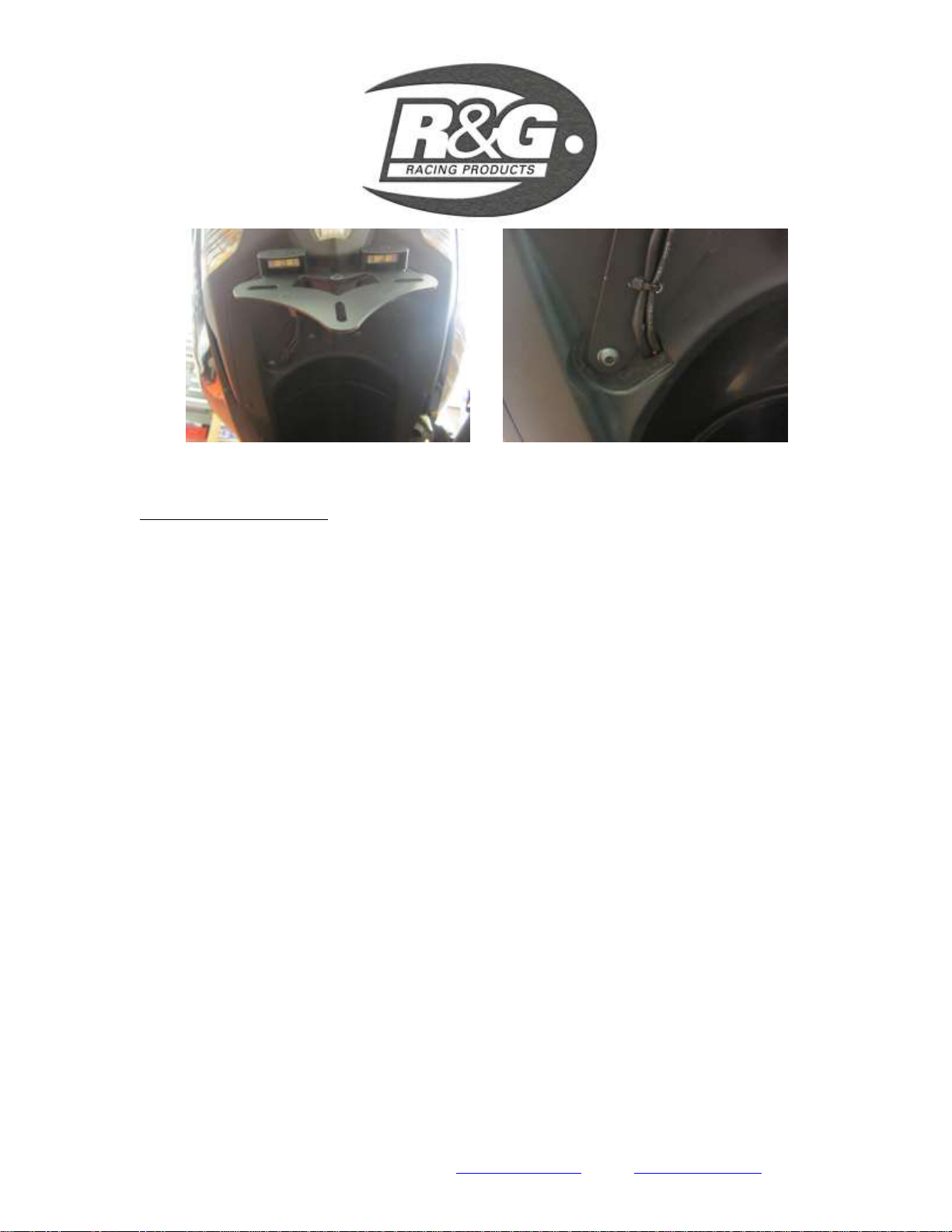
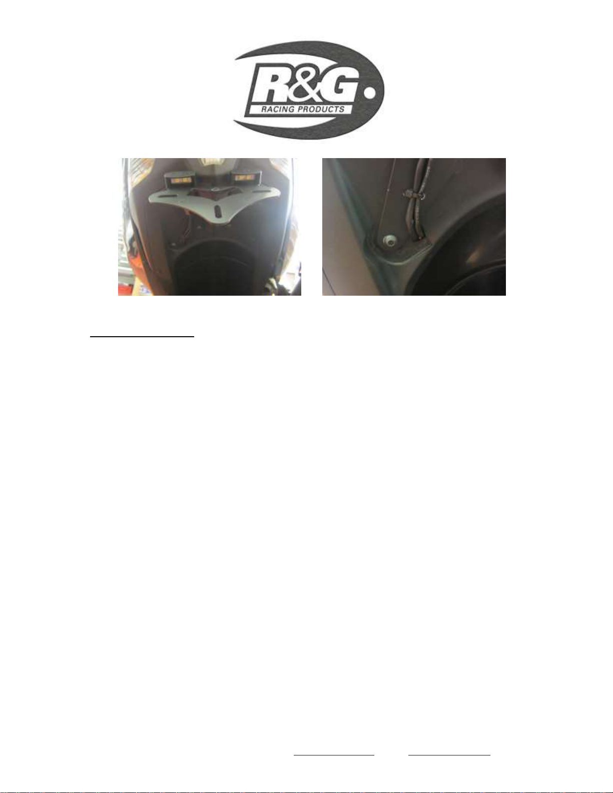
Abbildung 5 Abbildung 6
MONTAGEANLEITUNG
Öffnen Sie den Sitz.
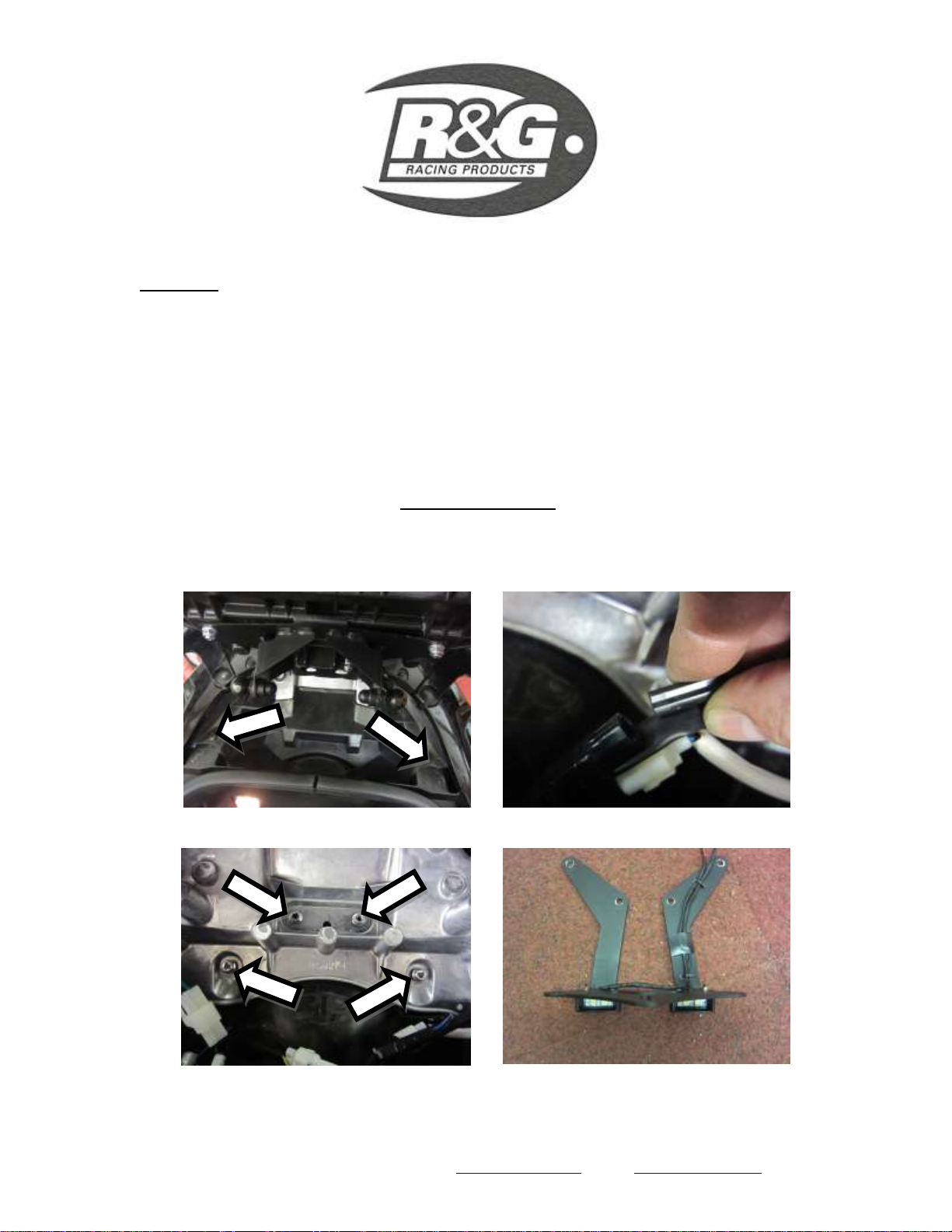
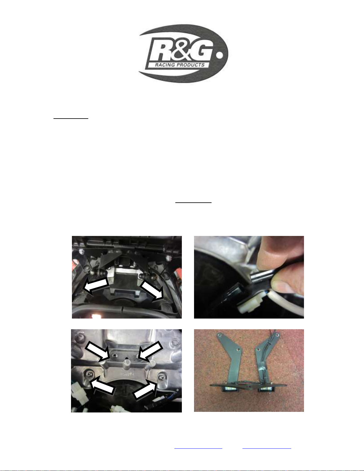
Entfernen Sie die zwei Nieten (Abbildung 1).
Entfernen Sie die zwei Gummiabdeckungen.
Lösen Sie den schwarzen Steckverbinder für die Kennzeichenbeleuchtung (Abbildung 2).
Halten Sie den Originalkennzeichenhalter und entfernen Sie vier Schrauben (Abbildung 3)
Entfernen Sie vorsichtig den Originalkennzeichenhalter (bitte aufpassen, dass der Steckverbinder
nicht beschädigt wird, wenn Sie das Kabel durch die untere Abdeckung ziehen).
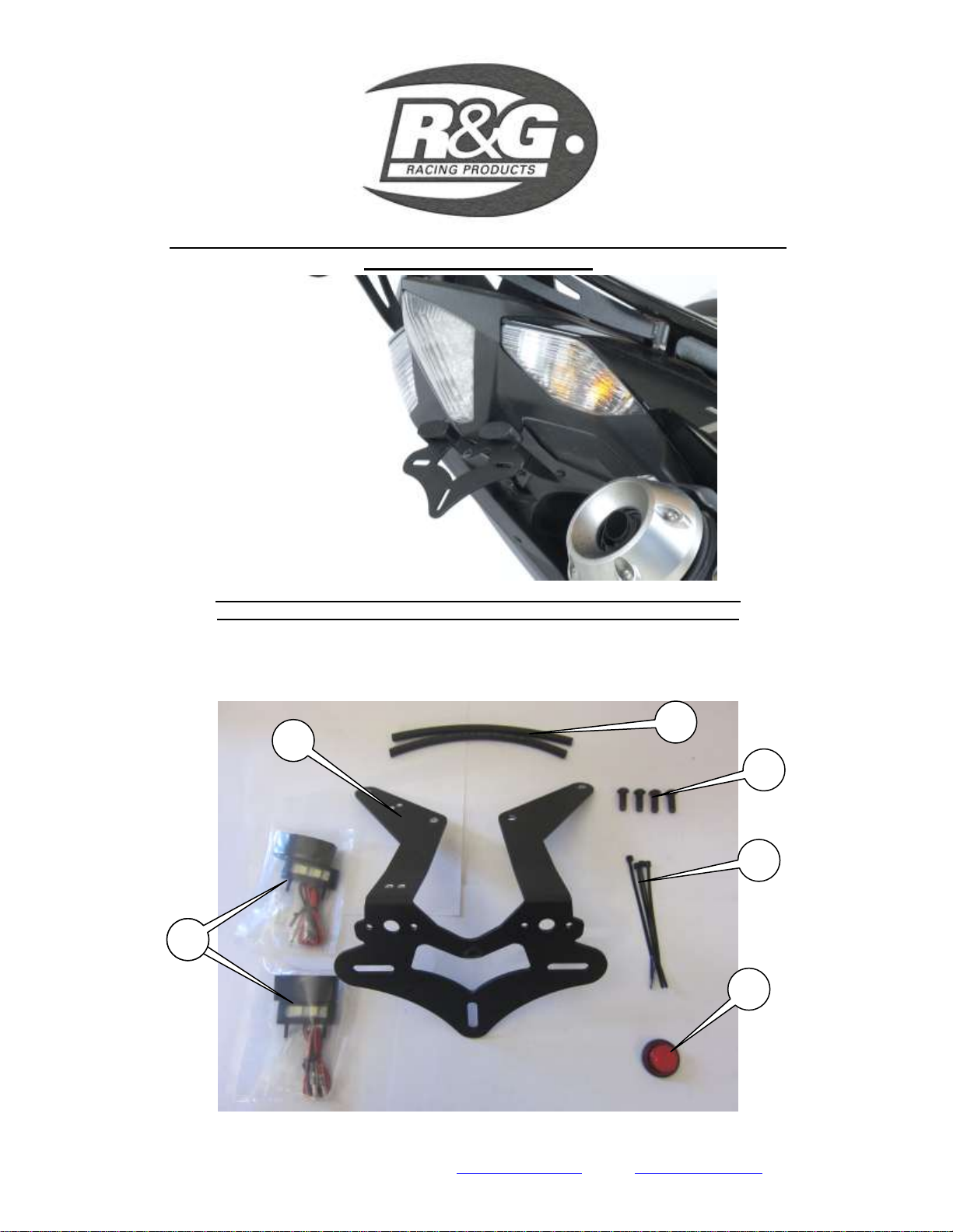
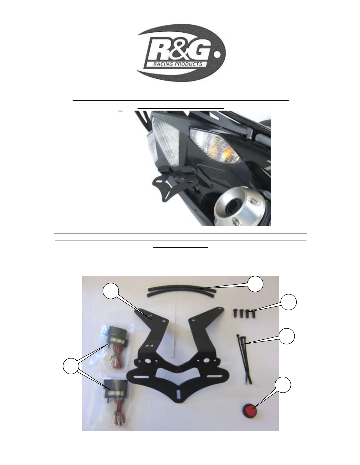
Nehmen Sie den R&G Kennzeichenhalter (Artikel 1 –TB0127) und montieren Sie die
Kennzeichenbeleuchtung (Artikel 6) wie abgebildet (Abbildung 4). Verbinden Sie die zwei Kabel
für die Kennzeichenbeleuchtung mittels der mitgelieferten Stecker. (Bitte beide schwarzen Kabel
miteinander verbinden und die beiden roten Kabel miteinander verbinden –verwenden Sie hierzu
die mitgelieferten Kabelverbinder). Kleben Sie die Lichtabdeckungen mit etwas Sekundenkleber
fest. (Bitte verwenden Sie den Schrumpfschlauch (Artikel 2), um die neuen
Kennzeichenbeleuchtungskabel zu schützen)
Die Kabel mittels Kabelbinder auf der unteren Seite des Kennzeichenhalters zusammenbinden, wie
abgebildet (Abbildung 4). Bitte die kleinen Löcher benutzen.
Den Kennzeichenhalter in Position bringen (Abbildung 5) und die Kabel wie ursprünglich durch
die untere Abdeckung führen (Abbildung 6).
Mit den vier Inbusschrauben (Artikel 3) und Originalmuttern fixieren.
Um die Kennzeichenbeleuchtung zu verbinden, empfehlen wir, den Original-
Kennzeichenbeleuchtungsstecker wieder zu verwenden. Die Originalverkabelung muss abgetrennt
und abisoliert werden (benutzen Sie hierfür die Verbindungsstecker im Kit). Überprüfen Sie die
Funktion der Kennzeichenbeleuchtung.
Montieren Sie die zwei Gummiabdeckungen.
Montieren Sie die zwei Nieten wie in Abbildung 1.
Montieren Sie das amtliche Kennzeichen (Bohrungen im Kennzeichen evtl. notwendig).
WICHTIG: WENN EIN GROSSES KENNZEICHEN ZU WEIT NACH UNTEN
MONTIERT WIRD, BESTEHT BEI SCHWEREM LAST ODER DURCH GROSSE
BODENWELLEN EIN GERINGES RISIKO, DASS DAS KENNZEICHEN AN DAS
HINTERRAD STOSSEN KANN. ES LIEGT IN IHRER VERANTWORTUNG DIES ZU
ÜBERPRÜFEN UND, WENN NOTWENDIG, VORZUBEUGENDE MASSNAHMEN ZU

R&G Racing
Unit 1, Shelley’s Lane, East Worldham, Alton, Hampshire, GU34 3AQ
ERGREIFEN. DIE NICHTBEACHTUNG DIESES SICHERHEITSHINWEIS KANN ZU
SCHWEREN VERLETZUNGEN FÜHREN.
Entsprechend der gesetzlichen Vorschriften, den mitgelieferten Rückstrahler an die dafür
vorgesehene Stelle anbringen.
Überprüfen Sie die Funktion der Beleuchtung (Blinker und Kennzeichenhalterbeleuchtung) vor
Gebrauch des Fahrzeuges.
AUSGABE 1 12/09/12 (NSY)
Table of contents
Languages:
Other R&G Motorcycle Accessories manuals
Popular Motorcycle Accessories manuals by other brands

Guardian Interlock Systems
Guardian Interlock Systems AMS2000 operating guide

MRA
MRA Multistrada V4 2021 Mounting instructions

DS18
DS18 RY-KIT8.HD owner's manual

Alba Racing
Alba Racing PRO ELITE RAPTOR 350 installation instructions

Ducati
Ducati 96781131A manual

OrbiMAX
OrbiMAX 3M Speedglas 9100MP Care & maintenance